EP1042149B1 - Dispositif de freinage assiste a securite passive - Google Patents
Dispositif de freinage assiste a securite passive Download PDFInfo
- Publication number
- EP1042149B1 EP1042149B1 EP98962537A EP98962537A EP1042149B1 EP 1042149 B1 EP1042149 B1 EP 1042149B1 EP 98962537 A EP98962537 A EP 98962537A EP 98962537 A EP98962537 A EP 98962537A EP 1042149 B1 EP1042149 B1 EP 1042149B1
- Authority
- EP
- European Patent Office
- Prior art keywords
- master cylinder
- booster
- braking device
- shell
- front shell
- Prior art date
- Legal status (The legal status is an assumption and is not a legal conclusion. Google has not performed a legal analysis and makes no representation as to the accuracy of the status listed.)
- Expired - Lifetime
Links
- 238000005192 partition Methods 0.000 claims description 10
- 238000000926 separation method Methods 0.000 description 4
- 230000035939 shock Effects 0.000 description 4
- 239000011324 bead Substances 0.000 description 3
- 238000010521 absorption reaction Methods 0.000 description 1
- 230000004323 axial length Effects 0.000 description 1
- 230000005540 biological transmission Effects 0.000 description 1
- 230000006378 damage Effects 0.000 description 1
- 230000000694 effects Effects 0.000 description 1
- 239000012528 membrane Substances 0.000 description 1
- 230000004048 modification Effects 0.000 description 1
- 238000012986 modification Methods 0.000 description 1
- 230000002093 peripheral effect Effects 0.000 description 1
- 230000008092 positive effect Effects 0.000 description 1
Images


Classifications
-
- B—PERFORMING OPERATIONS; TRANSPORTING
- B60—VEHICLES IN GENERAL
- B60T—VEHICLE BRAKE CONTROL SYSTEMS OR PARTS THEREOF; BRAKE CONTROL SYSTEMS OR PARTS THEREOF, IN GENERAL; ARRANGEMENT OF BRAKING ELEMENTS ON VEHICLES IN GENERAL; PORTABLE DEVICES FOR PREVENTING UNWANTED MOVEMENT OF VEHICLES; VEHICLE MODIFICATIONS TO FACILITATE COOLING OF BRAKES
- B60T13/00—Transmitting braking action from initiating means to ultimate brake actuator with power assistance or drive; Brake systems incorporating such transmitting means, e.g. air-pressure brake systems
- B60T13/10—Transmitting braking action from initiating means to ultimate brake actuator with power assistance or drive; Brake systems incorporating such transmitting means, e.g. air-pressure brake systems with fluid assistance, drive, or release
- B60T13/24—Transmitting braking action from initiating means to ultimate brake actuator with power assistance or drive; Brake systems incorporating such transmitting means, e.g. air-pressure brake systems with fluid assistance, drive, or release the fluid being gaseous
- B60T13/46—Vacuum systems
- B60T13/52—Vacuum systems indirect, i.e. vacuum booster units
- B60T13/567—Vacuum systems indirect, i.e. vacuum booster units characterised by constructional features of the casing or by its strengthening or mounting arrangements
Definitions
- Such braking devices are generally composed of a master cylinder and a pneumatic assistance servomotor, the servomotor comprising in particular a casing rigid, a movable partition defining at least one front chamber and one rear chamber, sealingly, inside the enclosure, a three-way valve actuated by a rod control to selectively admit different pressures in the front chambers and rear and correspondingly subject the movable partition to an assisting force acting in the direction of the master cylinder and a push rod connected to the movable partition, to activate the master cylinder, the envelope comprising a front shell integral with the master cylinder and forming wall for the front chamber, and a rear shell forming a wall for the rear chamber, the front and rear shells each comprising a radial shoulder, the cohesion of the front and rear shells being provided by a hoop cooperating with the shoulders of the front and rear shells.
- Devices of this type are well known in the prior art, as shown by example by patent document GB-A-2 136 520. They are usually arranged in the front compartment of a motor vehicle, generally containing the vehicle engine, the actuator being fixed by its rear wall to the separation apron between this compartment front and the passenger compartment, and the master cylinder being fixed on the front wall of the booster.
- the rod servomotor control unit passes through an opening in the bulkhead and is actuated by a brake pedal in the passenger compartment.
- the invention is situated in this context and aims to propose a new solution, likely to satisfactorily limit the transmission of a frontal or oblique shock in configurations where the known solutions prove to be insufficiently effective by providing a assisted braking device such as engine or load interference carried in the front compartment of the vehicle with the master cylinder is not transformed into a projection from the brake pedal to the driver of the vehicle, without using elements additional which would lengthen the axial length of the braking assembly in front of the bulkhead.
- a assisted braking device such as engine or load interference carried in the front compartment of the vehicle with the master cylinder is not transformed into a projection from the brake pedal to the driver of the vehicle, without using elements additional which would lengthen the axial length of the braking assembly in front of the bulkhead.
- the partial straps comprise each at at least one of their ends a tab extending radially outward from the servomotor, the adjacent legs of two consecutive partial straps being maintained one against each other by the locking device.
- the locking device has a fork formed at one end a rigid bar, the other end of which is integral with the front shell of the booster.
- the end of the rigid bar is secured to a plate itself secured to the front shell of the booster.
- the plate can be interposed between the front shell of the actuator and a master cylinder mounting flange.
- the end of at least one of the partial straps is formed with a tab forming a hook intended to cooperate with a tab of the partial strapping adjacent and extending radially outward from the booster.
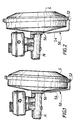
- the invention relates to a braking device assisted composed of a master cylinder M and a pneumatic servomotor of assistance S.
- the part of this assisted braking device is called the "front” last turn towards the master cylinder M and “rear” of this braking device the part facing the brake pedal.
- the front is thus on the left and the rear to the right.
- the actuator S includes in particular a rigid casing 10, a movable partition 12 sealingly defining a front chamber 14 and a rear chamber 16, inside the casing 10, a three-way valve tracks 18 actuable by a control rod 20, to selectively admit pressures different in the front 14 and rear 16 chambers and to correlate the partition mobile 12 with an assistance force directed towards the front, and a push rod 22 connected to the movable partition 12, for actuating the master cylinder M.
- the rigid envelope 10 itself comprises a front shell 24, also called a cylinder, integral with the master cylinder M and forming a wall for the front chamber 14, and a shell rear 26, also called cover, forming a wall for the rear chamber 16.
- the front shell 24 and the rear shell 26 are each formed with a shoulder radial 28, 30 respectively, serving to immobilize an outer peripheral bead 32 a flexible unrolling membrane 34 associated with the movable partition 12.
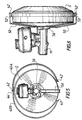
- a circular hoop 40 keeps tight one against the other the front 24 and rear 26 shells, via the shoulders 28 and 30 retaining between them the bead 32.
- the hoop 40 is formed by a ring 36 whose edges 37 and 38 are folded inwards so as to form flanks extending in planes parallel to each other and perpendicular to the axis of symmetry X-X 'of the servomotor.
- the circular hoop 40 is made up of two semicircular semi-straps 40A and 40B.
- the ends of each half-hoop are shaped so that the ring 36 projects a predetermined length from the sides 37 and 38.
- this additional length of the ring 36 is folded so as to extend radially relative to the center of curvature of the ring 36, and thus to form a tab 42, as shown in Figure 10
- One of the half-straps for example the half-strapping 40A, is formed with a tab 42 at each of its ends.
- the other half-band, for example half-band 40B, is formed with a tab 42, as has just been described, at one of its ends, while the other end is formed with a tab 44 shaped differently.
- the extra length of ring 36 is about twice as long as is needed to form a tab 42. This additional length is folded, like the previous one, radially relative to the center of curvature of the ring 36, then it is folded back on itself, at 180 degrees, so as to form the second branch of a hook, as shown in Figure 9, the two branches being substantially parallel and providing space between them of width slightly greater than the thickness of the ring 36.
- the front shells 24 and rear 26 are arranged one opposite the other so as to trap the annular bead 32 between their shoulders 28 and 30.
- Half-straps 40A and 40B can then be installed on the shoulders 28 and 30, so that the lug 44 of the half-hoop 40B comes to hang on the lug 42 of the half-hoop 40A.
- the other ends of the half-straps 40A and 40B each provided of a tab 42 can then be brought together to ensure the cohesion of the servomotor.
- This locking element 50 comprises a fork 52, enclosing the tabs 42 of the half-straps 40A and 40B, and formed at one curved end of a rigid bar 54 of which the other end is integral with a plate 56, held on the front shell 24, being for example sandwiched between the front shell 24 and the master cylinder M.
- the assisted braking device thus assembled can then be installed on a vehicle, and in particular by fixing the rear shell 26 to the bulkhead separating the engine compartment from the interior of this vehicle.
- the assisted braking device is then found in the configuration shown in Figures 1 and 3. It is therefore understood that, in such an arrangement, which is the most commonly used, the servomotor and the master cylinder are located in the extension from each other, and as a result the master cylinder forms a perpendicular projection an apron and the front end of which is located at a considerable distance from the apron.
- the rotation of the master cylinder relative to the front shell of the servomotor was simultaneously as a consequence of breaking the tightness of the front chamber 14 of the booster compared to the ambient atmosphere. It therefore follows that atmospheric pressure does not exert no more force capable of ensuring the cohesion of the servomotor.
- the front 24 and rear shells 26 are therefore free to detach from each other, and it follows that they can no longer transmit significant effort to the driver of the vehicle.
- FIG. 8 shows a variant of the embodiment which has just been described.
- the two half-straps ensuring the attachment of the shells of the servomotor are identical, and both have legs at their ends such that the tab 42 previously described.
- the two half-straps are held by two elements locking 50, diametrically opposite, and integral with the same plate 56.
- the comprises ment of the assisted braking device produced according to this alternative embodiment is identical to the one described above, except that the rotation of the master cylinder relative to the servomotor can intervene in two preferred directions to result in separation of the servomotor.
- partial straps in numbers greater than two, for example three partial straps each covering an angular sector of 120 degrees, two consecutive partial straps being joined by a locking element secured to the plate interposed between the servomotor and the master cylinder.
Landscapes
- Engineering & Computer Science (AREA)
- Transportation (AREA)
- Mechanical Engineering (AREA)
- Braking Systems And Boosters (AREA)
- Regulating Braking Force (AREA)
Applications Claiming Priority (3)
| Application Number | Priority Date | Filing Date | Title |
|---|---|---|---|
| FR9716221 | 1997-12-22 | ||
| FR9716221A FR2772707B1 (fr) | 1997-12-22 | 1997-12-22 | Dispositif de freinage assiste a securite passive |
| PCT/FR1998/002813 WO1999032340A1 (fr) | 1997-12-22 | 1998-12-22 | Dispositif de freinage assiste a securite passive |
Publications (2)
| Publication Number | Publication Date |
|---|---|
| EP1042149A1 EP1042149A1 (fr) | 2000-10-11 |
| EP1042149B1 true EP1042149B1 (fr) | 2002-07-31 |
Family
ID=9514893
Family Applications (1)
| Application Number | Title | Priority Date | Filing Date |
|---|---|---|---|
| EP98962537A Expired - Lifetime EP1042149B1 (fr) | 1997-12-22 | 1998-12-22 | Dispositif de freinage assiste a securite passive |
Country Status (11)
| Country | Link |
|---|---|
| US (1) | US6491355B1 (enExample) |
| EP (1) | EP1042149B1 (enExample) |
| JP (1) | JP4283439B2 (enExample) |
| KR (1) | KR20010031486A (enExample) |
| BR (1) | BR9815263A (enExample) |
| DE (1) | DE69806968T2 (enExample) |
| ES (1) | ES2181313T3 (enExample) |
| FR (1) | FR2772707B1 (enExample) |
| RU (1) | RU2218285C2 (enExample) |
| TR (1) | TR200001541T2 (enExample) |
| WO (1) | WO1999032340A1 (enExample) |
Families Citing this family (3)
| Publication number | Priority date | Publication date | Assignee | Title |
|---|---|---|---|---|
| FR2855129B1 (fr) * | 2003-05-22 | 2006-06-09 | Bosch Gmbh Robert | Dispositif de freinage de vehicule automobile et procede de montage |
| DE102004017631A1 (de) * | 2004-04-10 | 2005-10-27 | Daimlerchrysler Ag | Sicherheitsvorrichtung für ein Kraftfahrzeug mit einer Vorbaustruktur |
| FR2872760B1 (fr) * | 2004-07-07 | 2006-09-22 | Bosch Gmbh Robert | Dispositif de freinage pour vehicule automobile, dont certains elements sont assembles par clinchage |
Family Cites Families (8)
| Publication number | Priority date | Publication date | Assignee | Title |
|---|---|---|---|---|
| DE3203496A1 (de) * | 1982-02-03 | 1983-08-04 | FAG Kugelfischer Georg Schäfer & Co, 8720 Schweinfurt | Vorrichtung zur befestigung eines bremskraftverstaerkers und eines hauptbremszylinders |
| DE3307880A1 (de) * | 1983-03-05 | 1984-09-06 | Alfred Teves Gmbh, 6000 Frankfurt | Unterdruckgehaeuse fuer einen bremskraftverstaerker |
| DE3428868A1 (de) * | 1984-08-04 | 1986-02-13 | Alfred Teves Gmbh, 6000 Frankfurt | Halterung fuer ein mechanisch angesteuertes bremsgeraet |
| GB2230493A (en) * | 1989-04-11 | 1990-10-24 | Austin Rover Group | Reducing collision damage in vehicles |
| FR2656389B1 (fr) * | 1989-12-22 | 1992-03-20 | Bendix Europ Services Tech | Dispositif de protection peripherique, notamment de servomoteur de freinage pour vehicules automobiles. |
| RU2070522C1 (ru) * | 1990-05-14 | 1996-12-20 | Гродненский завод автомобильных агрегатов | Тормозная камера с пружинным энергоаккумулятором |
| DE4105744A1 (de) * | 1991-02-23 | 1992-08-27 | Teves Gmbh Alfred | Gehaeuse fuer einen unterdruck-bremskraftverstaerker |
| FR2729355A1 (fr) * | 1995-01-18 | 1996-07-19 | Alliedsignal Europ Services | Ensemble d'un servomoteur pneumatique d'assistance au freinage et d'un maitre-cylindre |
-
1997
- 1997-12-22 FR FR9716221A patent/FR2772707B1/fr not_active Expired - Fee Related
-
1998
- 1998-12-21 US US09/214,647 patent/US6491355B1/en not_active Expired - Lifetime
- 1998-12-22 JP JP2000525292A patent/JP4283439B2/ja not_active Expired - Lifetime
- 1998-12-22 RU RU2000120164/28A patent/RU2218285C2/ru not_active IP Right Cessation
- 1998-12-22 DE DE69806968T patent/DE69806968T2/de not_active Expired - Lifetime
- 1998-12-22 WO PCT/FR1998/002813 patent/WO1999032340A1/fr not_active Ceased
- 1998-12-22 TR TR2000/01541T patent/TR200001541T2/xx unknown
- 1998-12-22 EP EP98962537A patent/EP1042149B1/fr not_active Expired - Lifetime
- 1998-12-22 ES ES98962537T patent/ES2181313T3/es not_active Expired - Lifetime
- 1998-12-22 BR BR9815263-7A patent/BR9815263A/pt not_active IP Right Cessation
- 1998-12-22 KR KR1020007004523A patent/KR20010031486A/ko not_active Withdrawn
Also Published As
| Publication number | Publication date |
|---|---|
| EP1042149A1 (fr) | 2000-10-11 |
| FR2772707A1 (fr) | 1999-06-25 |
| DE69806968D1 (de) | 2002-09-05 |
| JP2001526152A (ja) | 2001-12-18 |
| WO1999032340A1 (fr) | 1999-07-01 |
| RU2218285C2 (ru) | 2003-12-10 |
| TR200001541T2 (tr) | 2000-12-21 |
| JP4283439B2 (ja) | 2009-06-24 |
| FR2772707B1 (fr) | 2000-02-11 |
| BR9815263A (pt) | 2001-10-16 |
| KR20010031486A (ko) | 2001-04-16 |
| DE69806968T2 (de) | 2003-02-06 |
| US6491355B1 (en) | 2002-12-10 |
| ES2181313T3 (es) | 2003-02-16 |
Similar Documents
| Publication | Publication Date | Title |
|---|---|---|
| EP2292483B1 (fr) | Système de freins à servofrein électrique | |
| EP0366504B1 (fr) | Ensemble d'un servomoteur de freinage monté sur une paroi fixe d'un vehicule | |
| EP0039271B1 (fr) | Servo-moteur d'assistance au freinage à renfort de fixation | |
| EP0802869B1 (fr) | Ensemble d'un servomoteur pneumatique d'assistance au freinage et d'un maitre-cylindre | |
| EP1042149B1 (fr) | Dispositif de freinage assiste a securite passive | |
| FR2511447A1 (fr) | Dispositif d'assistance a depression | |
| EP0800978B1 (fr) | Ensemble de colonne de direction à absorption d'énergie de choc, notamment pour véhicule automobile | |
| EP0767747A1 (fr) | Ensemble d'un servomoteur pneumatique d'assistance au freinage et d'un maitre-cylindre | |
| EP0848175B1 (fr) | Dispositif d'accouplement permanent de deux arbres | |
| EP0148670A2 (fr) | Dispositif de fixation d'un amplificateur pneumatique de freinage sur un véhicule automobile | |
| FR2488354A1 (fr) | Dispositif de transmission comportant un joint de cardan ou autre organe d'accouplement | |
| EP1071597B1 (fr) | Dispositif de freinage a entretoise simplifiee | |
| EP1351849B1 (fr) | Servomoteur pour freinage d'urgence comportant des moyens de verrouillage par obstacle radial | |
| EP0559570B1 (fr) | Accouplement élastique | |
| FR2633350A1 (fr) | Agencement d'un capot de protection sur la tulipe d'un joint de transmission | |
| EP0746487B1 (fr) | Servomoteur pneumatique d'assistance au freinage a enveloppe symetrique | |
| WO1996007574A1 (fr) | Servomoteur pneumatique d'assistance au freinage | |
| EP0961721B1 (fr) | Dispositif de freinage a zone de fragilite controlee | |
| EP1870306B1 (fr) | Servomoteur à tirants comportant une bague d'étanchéité renforcée | |
| EP0918000A1 (fr) | Antivol pour un arbre de colonne de direction de véhicule automobile | |
| EP0728088B1 (fr) | Servomoteur pneumatique a fonctionnement silencieux | |
| EP0796190B1 (fr) | Servomoteur pneumatique d'assistance au freinage | |
| FR2786737A1 (fr) | Dispositif pour le montage d'une pedale | |
| EP1439991B1 (fr) | Dispositif formant cloison mobile et etanche, en particulier pour servo-frein d'un circuit de freinage de vehicule automobile, et servo-frein equipe d'un tel dispositif. | |
| FR2534539A1 (fr) | Agencement de maitre-cylindre et amplificateur de force de freinage pour vehicule automobile |
Legal Events
| Date | Code | Title | Description |
|---|---|---|---|
| PUAI | Public reference made under article 153(3) epc to a published international application that has entered the european phase |
Free format text: ORIGINAL CODE: 0009012 |
|
| 17P | Request for examination filed |
Effective date: 20000328 |
|
| AK | Designated contracting states |
Kind code of ref document: A1 Designated state(s): DE ES FR GB IT |
|
| GRAG | Despatch of communication of intention to grant |
Free format text: ORIGINAL CODE: EPIDOS AGRA |
|
| 17Q | First examination report despatched |
Effective date: 20011128 |
|
| GRAG | Despatch of communication of intention to grant |
Free format text: ORIGINAL CODE: EPIDOS AGRA |
|
| GRAH | Despatch of communication of intention to grant a patent |
Free format text: ORIGINAL CODE: EPIDOS IGRA |
|
| GRAH | Despatch of communication of intention to grant a patent |
Free format text: ORIGINAL CODE: EPIDOS IGRA |
|
| GRAA | (expected) grant |
Free format text: ORIGINAL CODE: 0009210 |
|
| AK | Designated contracting states |
Kind code of ref document: B1 Designated state(s): DE ES FR GB IT |
|
| REG | Reference to a national code |
Ref country code: GB Ref legal event code: FG4D Free format text: NOT ENGLISH |
|
| REF | Corresponds to: |
Ref document number: 69806968 Country of ref document: DE Date of ref document: 20020905 |
|
| GBT | Gb: translation of ep patent filed (gb section 77(6)(a)/1977) |
Effective date: 20020916 |
|
| REG | Reference to a national code |
Ref country code: ES Ref legal event code: FG2A Ref document number: 2181313 Country of ref document: ES Kind code of ref document: T3 |
|
| PLBE | No opposition filed within time limit |
Free format text: ORIGINAL CODE: 0009261 |
|
| STAA | Information on the status of an ep patent application or granted ep patent |
Free format text: STATUS: NO OPPOSITION FILED WITHIN TIME LIMIT |
|
| 26N | No opposition filed |
Effective date: 20030506 |
|
| PGFP | Annual fee paid to national office [announced via postgrant information from national office to epo] |
Ref country code: FR Payment date: 20131213 Year of fee payment: 16 |
|
| REG | Reference to a national code |
Ref country code: FR Ref legal event code: ST Effective date: 20150831 |
|
| PG25 | Lapsed in a contracting state [announced via postgrant information from national office to epo] |
Ref country code: FR Free format text: LAPSE BECAUSE OF NON-PAYMENT OF DUE FEES Effective date: 20141231 |
|
| PGFP | Annual fee paid to national office [announced via postgrant information from national office to epo] |
Ref country code: ES Payment date: 20151218 Year of fee payment: 18 |
|
| PGFP | Annual fee paid to national office [announced via postgrant information from national office to epo] |
Ref country code: IT Payment date: 20151222 Year of fee payment: 18 |
|
| PG25 | Lapsed in a contracting state [announced via postgrant information from national office to epo] |
Ref country code: IT Free format text: LAPSE BECAUSE OF NON-PAYMENT OF DUE FEES Effective date: 20161222 |
|
| PGFP | Annual fee paid to national office [announced via postgrant information from national office to epo] |
Ref country code: GB Payment date: 20171221 Year of fee payment: 20 |
|
| PGFP | Annual fee paid to national office [announced via postgrant information from national office to epo] |
Ref country code: DE Payment date: 20180223 Year of fee payment: 20 |
|
| PG25 | Lapsed in a contracting state [announced via postgrant information from national office to epo] |
Ref country code: ES Free format text: LAPSE BECAUSE OF FAILURE TO SUBMIT A TRANSLATION OF THE DESCRIPTION OR TO PAY THE FEE WITHIN THE PRESCRIBED TIME-LIMIT Effective date: 20020731 |
|
| REG | Reference to a national code |
Ref country code: ES Ref legal event code: FD2A Effective date: 20181112 |
|
| REG | Reference to a national code |
Ref country code: DE Ref legal event code: R071 Ref document number: 69806968 Country of ref document: DE |
|
| REG | Reference to a national code |
Ref country code: GB Ref legal event code: PE20 Expiry date: 20181221 |
|
| PG25 | Lapsed in a contracting state [announced via postgrant information from national office to epo] |
Ref country code: ES Free format text: LAPSE BECAUSE OF FAILURE TO SUBMIT A TRANSLATION OF THE DESCRIPTION OR TO PAY THE FEE WITHIN THE PRESCRIBED TIME-LIMIT Effective date: 20161223 Ref country code: GB Free format text: LAPSE BECAUSE OF EXPIRATION OF PROTECTION Effective date: 20181221 |