EP1041702B2 - Stator manufacturing apparatus for forming wires in twisted shape - Google Patents
Stator manufacturing apparatus for forming wires in twisted shape Download PDFInfo
- Publication number
- EP1041702B2 EP1041702B2 EP00105881A EP00105881A EP1041702B2 EP 1041702 B2 EP1041702 B2 EP 1041702B2 EP 00105881 A EP00105881 A EP 00105881A EP 00105881 A EP00105881 A EP 00105881A EP 1041702 B2 EP1041702 B2 EP 1041702B2
- Authority
- EP
- European Patent Office
- Prior art keywords
- portions
- wires
- outside
- wire
- shaped
- Prior art date
- Legal status (The legal status is an assumption and is not a legal conclusion. Google has not performed a legal analysis and makes no representation as to the accuracy of the status listed.)
- Expired - Lifetime
Links
Images


Classifications
-
- H—ELECTRICITY
- H02—GENERATION; CONVERSION OR DISTRIBUTION OF ELECTRIC POWER
- H02K—DYNAMO-ELECTRIC MACHINES
- H02K15/00—Methods or apparatus specially adapted for manufacturing, assembling, maintaining or repairing of dynamo-electric machines
- H02K15/04—Methods or apparatus specially adapted for manufacturing, assembling, maintaining or repairing of dynamo-electric machines of windings, prior to mounting into machines
- H02K15/0414—Windings consisting of separate elements, e.g. bars, hairpins, segments, half coils
- H02K15/0421—Windings consisting of separate elements, e.g. bars, hairpins, segments, half coils consisting of single conductors, e.g. hairpins
- H02K15/0428—Windings consisting of separate elements, e.g. bars, hairpins, segments, half coils consisting of single conductors, e.g. hairpins characterised by the method or apparatus for simultaneously twisting a plurality of hairpins
-
- H—ELECTRICITY
- H02—GENERATION; CONVERSION OR DISTRIBUTION OF ELECTRIC POWER
- H02K—DYNAMO-ELECTRIC MACHINES
- H02K15/00—Methods or apparatus specially adapted for manufacturing, assembling, maintaining or repairing of dynamo-electric machines
- H02K15/04—Methods or apparatus specially adapted for manufacturing, assembling, maintaining or repairing of dynamo-electric machines of windings, prior to mounting into machines
- H02K15/0414—Windings consisting of separate elements, e.g. bars, hairpins, segments, half coils
-
- Y—GENERAL TAGGING OF NEW TECHNOLOGICAL DEVELOPMENTS; GENERAL TAGGING OF CROSS-SECTIONAL TECHNOLOGIES SPANNING OVER SEVERAL SECTIONS OF THE IPC; TECHNICAL SUBJECTS COVERED BY FORMER USPC CROSS-REFERENCE ART COLLECTIONS [XRACs] AND DIGESTS
- Y10—TECHNICAL SUBJECTS COVERED BY FORMER USPC
- Y10T—TECHNICAL SUBJECTS COVERED BY FORMER US CLASSIFICATION
- Y10T29/00—Metal working
- Y10T29/49—Method of mechanical manufacture
- Y10T29/49002—Electrical device making
- Y10T29/49009—Dynamoelectric machine
-
- Y—GENERAL TAGGING OF NEW TECHNOLOGICAL DEVELOPMENTS; GENERAL TAGGING OF CROSS-SECTIONAL TECHNOLOGIES SPANNING OVER SEVERAL SECTIONS OF THE IPC; TECHNICAL SUBJECTS COVERED BY FORMER USPC CROSS-REFERENCE ART COLLECTIONS [XRACs] AND DIGESTS
- Y10—TECHNICAL SUBJECTS COVERED BY FORMER USPC
- Y10T—TECHNICAL SUBJECTS COVERED BY FORMER US CLASSIFICATION
- Y10T29/00—Metal working
- Y10T29/49—Method of mechanical manufacture
- Y10T29/49002—Electrical device making
- Y10T29/4902—Electromagnet, transformer or inductor
- Y10T29/49071—Electromagnet, transformer or inductor by winding or coiling
-
- Y—GENERAL TAGGING OF NEW TECHNOLOGICAL DEVELOPMENTS; GENERAL TAGGING OF CROSS-SECTIONAL TECHNOLOGIES SPANNING OVER SEVERAL SECTIONS OF THE IPC; TECHNICAL SUBJECTS COVERED BY FORMER USPC CROSS-REFERENCE ART COLLECTIONS [XRACs] AND DIGESTS
- Y10—TECHNICAL SUBJECTS COVERED BY FORMER USPC
- Y10T—TECHNICAL SUBJECTS COVERED BY FORMER US CLASSIFICATION
- Y10T29/00—Metal working
- Y10T29/49—Method of mechanical manufacture
- Y10T29/49002—Electrical device making
- Y10T29/4902—Electromagnet, transformer or inductor
- Y10T29/49073—Electromagnet, transformer or inductor by assembling coil and core
-
- Y—GENERAL TAGGING OF NEW TECHNOLOGICAL DEVELOPMENTS; GENERAL TAGGING OF CROSS-SECTIONAL TECHNOLOGIES SPANNING OVER SEVERAL SECTIONS OF THE IPC; TECHNICAL SUBJECTS COVERED BY FORMER USPC CROSS-REFERENCE ART COLLECTIONS [XRACs] AND DIGESTS
- Y10—TECHNICAL SUBJECTS COVERED BY FORMER USPC
- Y10T—TECHNICAL SUBJECTS COVERED BY FORMER US CLASSIFICATION
- Y10T29/00—Metal working
- Y10T29/51—Plural diverse manufacturing apparatus including means for metal shaping or assembling
- Y10T29/5136—Separate tool stations for selective or successive operation on work
- Y10T29/5137—Separate tool stations for selective or successive operation on work including assembling or disassembling station
Definitions
- the present invention relates to a stator manufacturing apparatus according to claims 1 and 2 and also to a method for manufacturing a stator according to claims 11 and 13.
- a stator manufacturing apparatus and method for manufacturing a stator by connecting a plurality of twisted wires, each of which is formed by twisting a turning portion of a near letter U shaped wire having one straight line portion.
- This known stator manufacturing apparatus comprises a first holding jig, in which a first holding portion is arranged for holding one straight line portion, a second holding jig, in which a second holding portion is arranged for holding the another straight line portion, and a biasing mechanism for urging the turning portion downward toward the one and another straight line portions, when the first and second holding jigs are relatively moved so that one straight line portion may move more apart from the another straight line portion to twist the turning portion of the near letter U shaped wire.
- a stator of a large-scale starter to be installed in automobiles employs an electromagnetic coil having a large cross sectional area for flowing large electric current.
- a wire made of conductive material such as copper is formed in a near letter U shaped wire 10.
- a turning portion 12 of the near letter U shaped wire 10 is twisted so that a twisted wire 1 or twisted double wires 6 may be formed (refer to Fig. 7).
- the twisted wires 1 are press fitted for assembly into slots of a yoke and, after assembly to the yoke, both ends thereof are further deformed and connected with each other by welding and so on to complete the electromagnetic coil.
- a twisting formation apparatus 100 for mass-producing the twisted wile 1, as shown in Fig. 10, is provided with an outside holding ring 41 and an inside holding ring 35, into which a pair of straight line portions 11, 11' of the near letter U shaped wire 10 are separately inserted and held respectively and which are arranged concentrically, and further provided with an inside jig.3 and an outside jig 4 which are relatively rotatable.
- a twisting formation of the near letter U shaped wire 10 is conducted in a manner that the respective straight line portions 11, 11' of a plurality of the near letter U shaped wires are inserted into the inside and outside holding rings 35 and 45, upper ends of all of the turning portions 12 are initially aligned or fixed on an upper side by a retaining element 101, and, then, the turning portions 12 are twisted by a relative rotating movement of the inside and outside jigs 3 and 4.
- a stator manufacturing apparatus for twisting turning portions of approximately U-shaped wires by concentric holding jigs in combination with a pressing mechanism acting on turning portions of said wires is known from SU 1 115 170.
- the present invention has been made in view of the above mentioned problem, and an object of the present invention is to provide a twisting formation apparatus in which a plurality of the near letter U shaped twisted wires or near letter U shaped twisted double wires are formed in a uniform shape at a time.
- the twisting formation apparatus enables to form at a time in a uniform twisted shape a plurality of the near letter U shaped wires, in a manner that at least either the turning portion or respective leading ends of the straight line portions are urged toward the straight line portions by biasing means.
- the twisted wires may be formed in a uniform shape, but also a generator or a motor such as a starter necessitating a large amount of the near letter U shaped wires may be manufactured with a minimum cost.
- a generator or a motor such as a starter necessitating a large amount of the near letter U shaped wires may be manufactured with a minimum cost.
- plural kinds of near letter U shaped double wires piled up with each other are formed in a uniform twisted form.
- the first and second supporting portions support the respective leading ends of pair of straight line portions of the wire arranged most outside at predetermined positions in respective axial directions of pair of straight line portions.
- each of pair of straight line portions is prevented from being relatively moved in an axial direction of each of the straight line portions from the first or second holding jig.
- the near letter U shaped wires partly project out of the first and second holding jigs.
- the respective wires projecting on the turning portion side have lengths to an extent that, when the first and second holding jigs are relatively moved, only the respective projecting turning portions are deformed and, thus, the respective straight line portions held in the first and second holding jigs are not drawn out toward the turning portions.
- the first and second supporting portions serve to prevent damages of the near letter U shaped wires due to frictions between the respective straight line portions and the respective holding jigs.
- the near letter U shaped wires in pile are respectively provided with the turning portions having different curvature radiuses. Therefore, a starting portion where the wire arranged inside (inside wire) is deformed is more far away from a center of the turning portion than a starting portion where the wire arranged outside (outside wire) is deformed. As a result, after the twisting formation process, a height length of the inside wire becomes shorter than that of the outside wire.
- the stator manufacturing apparatus is provided with the second biasing mechanism for urging the leading ends of the straight line portions of the inside wire.
- a twisted shape fluctuation of the turning portion (turning portion 63) of the inside wire may be prevented, as the inside wire is twisted also at a state that a movement in an axial direction thereof is restricted.
- the stator manufacturing apparatus is provided with the third biasing mechanism for urging respective leading ends of the straight line portions of the outside wire toward respective directions of the straight line portions, after the turning portions of the plural kinds of near letter U shaped wires arranged in piles have been twisted.
- the respective leading end positions of the outside wire are accurately aligned by the third biasing mechanism for deforming the outside wire, even if the respective leading end positions are fluctuated to some extent during the previous process, so as to absorb such a fluctuation.
- the first holding portion is formed in a ring shape and the second holding portion is also formed in a ring shape on an outer circumference side of and concentrically with the first holding portion. Therefore, a relative rotating movement of the first and second holding jigs cause to twist the turning portions of the near letter U shaped wire or double wires.
- the twisted wires formed as above mentioned are, then, inserted into slots of a stator core. The insertion into the slots becomes easy because the stator core is formed generally in a ring shape.
- Figs. 1 to 3 show a twisting formation apparatus 100 for forming a near letter U shaped wire in a twisted shape as a stator manufacturing apparatus.
- the twisting formation apparatus 100 is for forming a near letter U shaped wire 10 in a twisted shape as shown in Fig. 7 and manufactures at a time a large amount of the twisted wires 1 as electromagnetic coil elements to be used in a stator for a starter and so on.
- the near letter U shaped wire 10 is made by forming in a near letter U shape a predetermined length of a rectangular cross sectional shaped conductive wire coated by insulating material and composed of straight line portions 11, 11' and an arc shaped connecting portion 12 (turning portion).
- the near letter U shaped wire 10 may be a circular or other cross sectional shaped wire and the connecting portion 12 may be formed in, beside the arc shape, a near letter V shape or a near trapezoidal shape.
- the apparatus 100 for forming in a twisted shape the near letter U shaped wires is provided with a casing 2 composed of a base plate 21, and a cylindrical shaped center axis tube 22 and an external tube 23 both of which have a common center axis and are concentrically fixed to the base plate 21.
- An inside retaining ring 24 and an outside retaining ring 25 are fastened respectively to upper ends of the center axis and external tubes 22 and 23.
- An arm-inserting window 26 is provided at a lower end of the external tube 23.
- a cylindrical shaped inside jig 3 (first holding jig) is slidably fitted to an outside of the center axis tube 22.
- a cylindrical shaped outside jig 4 (second holding jig) is located outside the inside jig 3 and is slidably fitted to an inside of the external tube 23.
- An upper end internal circumference of the inside jig 3 is slidably retained by the inside retaining ring 24 and an upper end external circumference of the outside jig 4 is slidably retained by the outside retaining ring 25.
- An inside holding ring 31 is attached to an upper end surface of the inside jig 3.
- the inside jig 3 is provided at an upper external circumference thereof with a diameter-reduced portion 33 having an external circumferential step 32 and at a lower end thereof with a flange portion 34.
- the inside holding ring 31 is provided with an inside holding portion 35 constituted by rectangular shaped holes arranged in a ring shape, in which one of the straight line portions 11, 11' of the near letter U shaped wire is inserted.
- An external circumference of the flange portion 34 abuts an internal circumference surface of the external tube 23.
- a lower side arm 36 extending in a radial direction through the arm-inserting window 26 is connected to an external circumference portion of the flange 34.
- a lower end surface of the outside jig 4 is slidably placed on the flange portion 34 and the outside holding ring 41 is fastened to an upper end surface of the outside jig 34.
- the outside jig 34 is provided at an upper internal circumference thereof with a diameter-enlarged portion 43 having an internal circumference step 42.
- the outside holding ring 41 is provided with an outside holding portion 45 constituted by rectangular shaped holes arranged on a circle, in which the other of the straight line portions 11, 11' of the near letter U shaped wire is inserted.
- the outside holding portion 45 is faced to and arranged concentrically with the inside holding portion 35.
- a pair of pillars 29, 29 are provided in the base plate 21 in a manner that the external tube 23 is put between the pair of pillars 29, 29.
- An upper base plate 27 is fixed horizontally to upper ends of the pillars 29, 29.
- the upper base plate 27 is provided with a round hole 28 concentrically with the center axis tube 22 and a biasing mechanism 5 urging the near letter U shaped wires 10 with a contraction force.
- the biasing mechanism is composed of an expanding and contracting actuator 51, a moving arm 52 driven to move up and down by the actuator 51 and a biasing disk plate 53 fastened at a lower end of the moving arm 52.
- the arm 52 is disposed through the round hole 28.
- the biasing disk plate 53 has a size sufficient to come in contact with all of the connecting portions 12 of the near letter U shaped wires 10.
- the expanding and contracting actuator 51 may be an actuator causing a reciprocal up and down movement of the arm 52 by means of a cylinder and a hydraulically or aerodynamically-operated piston, or by means of a combination of a motor and a ball screw.
- the biasing mechanism 5 may be of a type that a weight of the biasing disk plate 53 is utilized.
- the respective straight line portions 11, 11' of the near letter U shaped wires 10 are inserted into all of the respective rectangular holes of the inside and outside holding portions 35 and 45.
- the leading ends of the straight line portions 11, 11' come in contact with the external and internal circumference steps 32 and 42, respectively.
- the arm 52 is moved downwardly so that the biasing disk plate 53 may be moved down, as shown by a two dots-slash line in Fig. 1, to urge all of the connecting portions 12 of the near letter U shaped wires 10 downwardly in the drawing.
- certain contraction forces generates in the entire near letter U shaped wires 10 between the external and internal circumference steps 32 and 42 and the biasing disk plate 53.
- each of the connecting portions 12 is formed in a twisted shape by rotating the lower and upper side arms 36 and 44 by identical angles in opposite directions respectively in such a manner that both sides of the connecting portion 12 are uniformly deformed centered on a top of the connecting portion 12.
- the near letter U shaped wires 10 are installed in the inside and outside jigs 3 and 4, all of the near letter U shaped wires 10 are formed in twisted shapes at a time when the inside and outside jigs 3 and 4 are relatively rotated. That is, a large amount (for example 96 pieces) of the twisted wires 1 as shown in Fig. 7 are manufactured at a time.
- the expanding and contracting actuator 51 urges downward with a certain biasing force (torque) the connecting portions 12 via the biasing disk plate 53.
- a certain biasing force torque
- the contraction force is always applied between the connecting portion 12 and the respective leading ends of the straight line portions 11, 11.
- the contraction force thus applied serves to surely prevent the fluctuation of the twisted shape of the connecting portion 12.
- the connecting portion 12 of the near letter U shaped wire 10 is formed in the twisted shape, the height position of the connecting portion 12 becomes lower, as a space between the straight line portions 11, 11' is expanded more largely.
- the biasing disk plate 53 is so movable up and down that, as the height position of the connecting portion 12 becomes lower, the biasing disk plate 53 moves downward to follow the connecting portion 12 and continues to urge the connecting portion 12 with a certain biasing force.
- the connecting portion 12 is formed in the twisted shape in a manner that the inside and outside jigs hold the straight line portions 11, 11' of the near letter U shaped wire 10 always at respective predetermined positions. Therefore, the fluctuation of the twisted shape of the connecting portion 12 may be prevented.
- the leading ends of the straight portions 11, 11' are further formed to bend and, then, each of the leading ends of one of the twisted wires 1 is connected to each of the leading ends of another of the twisted wires 1 to complete the stator coil.
- the respective leading end positions of the straight line portions 11, 11' are aligned due to the contraction force applied by and between the biasing disk plat 53 and the external and internal circumference steps 32 and 42, as shown in the present embodiment, it is not necessary to align the respective positions of the leading ends of twisted wires 1, separately, when the respective leading ends are connected to each other. This will result in an easy manufacturing process for connecting the wires.
- the twisted wires 1 are assembled to the slots of the stator core arranged in a ring shape around the rotor.
- the holding portions (the inside holding portion 35 and the outside holding portion 45) for holding the straight line portions 11, 11' of the near letter U shaped wires 10 are arranged on respective concentric circles, the assembly of the twisted wires 1 to the slots, as a next process to the twisting formation process, becomes easy.
- FIGs. 4 to 6 show an embodiment according to the invention.
- a wire twisting apparatus 200 as another stator manufacturing apparatus according to the embodiment is for manufacturing twisted double wires 6 by forming at a time in twisted shapes near letter U shaped two wires comprising an outside wire 6A and an inside wire 6B piled up outside and inside, as shown in Fig. 8.
- the inside and outside jigs 3 and 4 are provided respectively with middle outside diameter and middle inside diameter portions 38 and 48 having lower external and lower internal circumference steps 37 and 47 at respective downsides of the external and internal circumference steps 32 and 42.
- spring type biasing means 7 for urging the straight line portions 61, 61' of the inside wire 6B toward the connecting portion 63.
- the spring type biasing means is composed of movable external and internal tubes 71 and 72 fitted movably in an up and down direction to the middle outside and inside diameter portions 38 and 48, respectively, and coil springs 73 and 74 disposed between lower ends of the movable external and internal tubes 71 and 72 and the lower external and lower internal circumference steps 37 and 47, respectively.
- the rectangular shaped holes of the inside and outside holding portions 35 and 45 correspond in size to cross sectional shapes of the straight line portions 11, 11' of the near letter U shaped double wires 60.
- the straight line portions 11, 11' of the near letter U shaped double wires 60 are inserted into the inside and outside holding portions 35 and 45, respectively, the leading ends of the straight portions 62, 62' of the outside wire 6A come in contact with the external and internal circumference steps 32 and 42 and the leading ends of the straight portions 61, 61' of the inside wire 6B come in contact with the movable external and internal tubes 71 and 72.
- each of the connecting portions 64 is formed in a twisted shape by rotating the lower and upper side arms 36 and 44 by identical angles in opposite directions in such a manner that both sides of the connecting portion64 are uniformly deformed centered on the top portion of the connecting portion 64.
- the connecting portion 64 is twisted without the fluctuation of the twisted shape of the connecting portion 64.
- the near letter U shaped double wires 60 project on sides of the connecting portions 63 and 64 out of the inside and outside holding portions 35 and 45, respectively.
- the respective double wires projecting on the sides of the connecting portions 63 and 64 have lengths to an extent that, when the inside and outside holding portions 35 and 45 are rotated relatively in opposite directions, only the respective projecting connecting portions 63 and 64 are deformed and the respective straight line portions 61 and 62 held in the inside and outside holding portions 35 and 45 are not drawn out substantially in directions of the connecting portions 63 and 64.
- each straight portion 62 of the outside wire 6A is held at a predetermined position in an axial direction of each straight line portion 62 by the external or internal circumference step 32 or 42. Therefore, the each straight portion 62 can not move in an axial direction thereof, and the each straight portion 62 may not be further pushed into the inside or outside holding portion 35 or 45 by the biasing disk plate 53. Therefore, when the near letter U shaped double wires 60 are formed in the twisted shapes, the outside wire 6A may be prevented from a damage due to a friction between the each straight line portion 62 and the inside or outside holding portion 35 or 45.
- the inside wire 6B when the inside wire 6B is inserted into the inside and outside jigs 3 and 4, the inside wire 6B is put between a lower surface of the connecting portion of the outside wire 6A and the spring type biasing means 7 and receives a force in a contraction direction therefrom.
- the inside wire 6B is hardened in a higher degree when the inside wire 6B is bent to form in the letter U shape. Therefore, at the twisting formation process, the twisting of the connecting portion 63 of the inside wire 6B starts at positions more far away from the center thereof, compared with the twisting of the connecting portion 64 of the outside wire 6A. As a result, after the twisting formation process, the length of the inside wire 6B becomes shorter than that of the outside wire 6A.
- the leading ends of the straight line portions 61, 61' of the inside wire 6B are urged toward the biasing disk plate 53 by the coil springs 73 and 74 via the movable external and internal tubes 71 and 72, respectively. Therefore, when the connecting portion 63 of the inside wire 6B is twisted, the movable external and internal tubes 71 and 72 move upward by a length corresponding to the shorter length resulted in the inside wire 6B. Thus, the upper surface of the connecting portion 63 of the inside wire 6B keeps to be pressed against the lower surface of the connecting portion 64 of the outside wire 6A. Therefore, as the inside wire 6B is also twisted at a state that an axial movement is restricted, no fluctuation of the twisted shape of the connecting portion 63 of the inside wire 6B may be generated.
- the leading ends of the straight portions 61 and 62 are further formed to bend.
- the respective layers of the straight line portions 61 and 62 of the twisted double wires 6 exposed out of the respective leading ends of the slots are twisted alternately in the adjacent layers in opposite circumferential directions by a predetermined angle (for example, angle corresponding to 1.5 slots).
- first and third layers of the straight line portions 61 and 62 viewed from an internal diameter side of the stator core are twisted in one circumferential direction by the predetermined angle and second and fourth layers of the straight line portions 61 and 62 are twisted in the other circumferential direction (direction opposite to that of the first and third layers) by the predetermined angle (same angle with the first and third layers).
- adjacent leading ends of the outside and inside wires 6A and 6B are respectively connected by welding and the like to complete the stator core.
- Fig. 9 shows a twisting apparatus 300 as a further stator manufacturing apparatus according to another embodiment of the present invention.
- the twisting apparatus 300 is composed of a base plate 311, an inside jig 321, an outside jig 331 and a coil biasing mechanism 340.
- a cylindrical shaped center axis tube 312 and a cylindrical shaped external tube 313 positioned concentrically and outside the center axis tube 312 are fixed perpendicularly to the base plate 311.
- the inside and outside jigs 321 and 331 are rotatably housed between the center axis tube 312 and the external tube 313.
- step portions 312a and 313a for holding in an axial direction the inside and outside jigs 321 and 331, respectively.
- inside and outside retaining rings 314 and 315 for restricting axial upward movement of the inside and outside jigs 321 and 331,respectively.
- the inside jig 321 is provided at an upper end surface thereof with an inside holding ring 322.
- a lower side arm 323 for transmitting rotation torque to the inside jig 321 is connected at a lower portion of the inside jig 321.
- the first and second positioning rings 324 and 325 are connected through a pin 326 to the inside jig 321 and rotatable together with the inside jig 321.
- the first and second positioning rings 324 and 325 are connected through a penetrating hole provided in the base plate 311 to a drive motor (not shown in the drawing) and respectively independently movable in an axial direction (up and down directions in the drawing).
- the first and second positioning rings 324 and 325 are provided with slits 324a and 325a extending in axial directions thereof. Circumferential width of the slit 324a or 325a is same with circumferential thickness of the pin 326 provided at an axially intermediate portion of the inside jig 321 and extending toward an outer diameter side thereof. An engagement of the pin 326 with the slits 324a and 325a enables to transmit the rotation force rendered to the inside jig 321 to the first and second positioning rings 324 and 325.
- the axial lengths of the slits 324a and 325a is long to an extent that the pin 32 does not prevent a movement of the first and second positioning rings 324 and 325 for moving upward the near letter U shaped double wires 60 after finishing the twist formation thereof.
- the outside jig 331 is composed of the similar structure to the inside jig 321. That is, the outside jig 331 is provided at an upper end surface thereof with an outside holding ring 332. An upper side arm 333 for transmitting rotation torque to the outside jig 331 is connected at a lower portion of the outside jig 331. Adjacent to the outside jig 331, rotatably provided are cylindrically shaped third and fourth positioning rings 334 and 335 for positioning leading lower ends 62b and 61b of the other of the outside and inside wires 6A and 6B, respectively.
- the third and fourth positioning rings 334 and 335 are connected through a pin 326 to the outside jig 331 and rotatable together with the outside jig 331.
- the third and fourth positioning rings 334 and 335 are connected through a penetrating hole provided in the base plate 311 to the drive motor (not shown in the drawing) and respectively independently movable in an axial direction (up and down directions in the drawing).
- the third and fourth positioning rings 334 and 335 are also provided with slits 334a and 335a extending in axial directions thereof, as are same with the first and second positioning rings 324 and 325.
- the coil biasing mechanism 340 is composed of an inside guide 341, a biasing disk plate 342, a spring 343 and a driving motor (not shown in the drawing).
- the inside guide 341 is for guiding an inside diameter portion of the outside wire 6A after the straight line portions 61 and 62 of the near letter U shaped double wires 60 are inserted into inside and outside holding portions formed in inside and outside holding rings 322 and 332 and, then, twisted.
- the inside guide 341 is composed of a disk portion 341a having a diameter corresponding to the inside diameter of the near letter U shaped double wires 60 arranged in circle shapes, and a shaft 341b extending perpendicularly from a center of the disk portion 341a.
- the biasing disk plate 342 is movable up and down along the shaft 341b by a drive motor (not shown in the drawing).
- the spring 343 is provided between the inside guide 341 and the biasing disk plate 342 and urges the inside guide 341 downward.
- the disk plate portion 341a of the inside guide 341 is inserted into the inside diameter portion of the near letter U shaped double wires 60 arranged in ring shapes. Then, the biasing disk plate 342 further moves down relative to the inside guide 341 so as to come in contact with the top portion of the connecting portion 64 of the outside wire 6A.
- the first to fourth positioning rings 324, 325, 334 and 335 move up by means of the drive motor (not shown) to support the lower ends of the near letter U shaped double wires 60, respectively.
- the axial movements of the near letter U shaped double wires 60 are restricted by the biasing disk plate 342 and the first to fourth positioning rings 324, 325, 334 and 335.
- the drive motor (not shown) controls the biasing disk plate 342 to keep pressing against the top portion of the outside wire 6A with a certain torque so that a predetermined contacting force may be applied to the outside wire 6A.
- the connecting portions 63, 64 of the outside and inside wires 6A and 6B are simultaneously twisted by the lower and upper arms 323 and 333 being rotated each other in opposite directions by the identical angles (for example, angle corresponding to 1.5 slots) by the rotation device (not shown in the drawing).
- the first and fourth positioning rings 324 and 335 supporting the leading ends 62a and 62b of the outside wire 6A are held at predetermined axial positions.
- the biasing disk plate 342 moves more downward to follow the connecting portion 64, since the biasing disk plate 342 continues to press the connecting portion 64 with the certain torque. As a result, the connecting portion is twisted without the twisted shape fluctuation of the connecting portion 64.
- a length of the inside wire 6B after the twisted formation becomes shorter than that of the outside wire 6A, as mentioned in the second embodiment.
- the driving motor (not shown) controls the second and third positioning rings 325 and 334 supporting the leading ends 61a and 61b of the straight portions 61 of the inside wire 6B to urge the leading ends 61a and 61b with a certain torque at the twisted formation process.
- the second and third positioning rings 325 and 334 moves upward by a distance corresponding to the distance by which the inside wire 6B becomes shorter when the connecting portion 63 thereof is twisted. Therefore, as the upper surface of the connecting portion 63 of the inside wire 6B keeps in pressing contact with the lower surface of the connecting portion 64 of the outside wire 6A. As a result, no twisted shape fluctuations of the connecting portions 63 of the inside wires 6B may generate, as the inside wires 6B are also twisted under the axial movement restriction.
- the first and fourth positioning rings 324 and 335 supporting the leading ends 62a and 62b of the outside wire 6A move upward with a predetermined torque or by a predetermined distance, while the biasing disk plate 342 urges the connecting portion 64 of the outside wire 6A.
- the fluctuation of the leading end positions of the outside wires 6A which may have occurred to some extent before the upward movement, may be absorbed so that the leading ends of the outside wires 6A may be accurately aligned.
- twisting formation process is described as the case of piling up doubly the outside and inside wires 6A and 6B.
- double wires it may be possible to form in twisted shapes the near letter U shaped wires piled up triply and more.
- stator coil is made by connecting the rectangular cross sectional wires.
- cross section thereof is not limited to be of the rectangular shape but may be of circular, oval or polygonal shape other than the rectangular shape.
Landscapes
- Engineering & Computer Science (AREA)
- Manufacturing & Machinery (AREA)
- Power Engineering (AREA)
- Manufacture Of Motors, Generators (AREA)
- Wire Processing (AREA)
Description
- The present invention relates to a stator manufacturing apparatus according to
claims 1 and 2 and also to a method for manufacturing a stator according toclaims 11 and 13. - From EP-A-0 162 317 a stator manufacturing apparatus and method are known for manufacturing a stator by connecting a plurality of twisted wires, each of which is formed by twisting a turning portion of a near letter U shaped wire having one straight line portion. This known stator manufacturing apparatus comprises a first holding jig, in which a first holding portion is arranged for holding one straight line portion, a second holding jig, in which a second holding portion is arranged for holding the another straight line portion, and a biasing mechanism for urging the turning portion downward toward the one and another straight line portions, when the first and second holding jigs are relatively moved so that one straight line portion may move more apart from the another straight line portion to twist the turning portion of the near letter U shaped wire.
- A stator of a large-scale starter to be installed in automobiles employs an electromagnetic coil having a large cross sectional area for flowing large electric current.
- To manufacture the electromagnetic coil, at first, a wire made of conductive material such as copper is formed in a near letter U shaped
wire 10. Next, aturning portion 12 of the near letter U shapedwire 10 is twisted so that a twisted wire 1 or twisteddouble wires 6 may be formed (refer to Fig. 7). - The twisted wires 1 are press fitted for assembly into slots of a yoke and, after assembly to the yoke, both ends thereof are further deformed and connected with each other by welding and so on to complete the electromagnetic coil.
- A
twisting formation apparatus 100 for mass-producing the twisted wile 1, as shown in Fig. 10, is provided with anoutside holding ring 41 and an inside holdingring 35, into which a pair ofstraight line portions 11, 11' of the near letter U shapedwire 10 are separately inserted and held respectively and which are arranged concentrically, and further provided with an inside jig.3 and anoutside jig 4 which are relatively rotatable. - According to this conventional
twisting formation apparatus 100, a twisting formation of the near letter U shapedwire 10 is conducted in a manner that the respectivestraight line portions 11, 11' of a plurality of the near letter U shaped wires are inserted into the inside andoutside holding rings portions 12 are initially aligned or fixed on an upper side by aretaining element 101, and, then, the turningportions 12 are twisted by a relative rotating movement of the inside and outsidejigs - However, in the
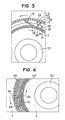
twisting formation apparatus 100 mentioned above, when theretaining element 101 is operative for initial alignment of the upper ends of the turning portions, a gap A comes out in height direction since a pull is given to theturning portion 12 by a deformation of the near letter U shapedwire 10. On the other hand, when the retaining element fixes the upper end of theturning portion 12, thestraight line portions 11,11' are moved upward as the turning portion is pulled up during the formation of the near letter U shapedwire 10. Thus, there exists a state that the near letter U shapedwire 10 is not supported in an up and down direction is fixed by one point during the deformation process, resulting in a problem that the twisted shape formation of the turning portion is not likely to be uniform. - A stator manufacturing apparatus for twisting turning portions of approximately U-shaped wires by concentric holding jigs in combination with a pressing mechanism acting on turning portions of said wires is known from SU 1 115 170.
- The present invention has been made in view of the above mentioned problem, and an object of the present invention is to provide a twisting formation apparatus in which a plurality of the near letter U shaped twisted wires or near letter U shaped twisted double wires are formed in a uniform shape at a time.
- In connection with the inventive stator manufacturing apparatus the above object is solved by the features of claim 1 and the method steps of claim 9.
- Improved embodiments of the inventive stator manufacturing apparatus result from
subclaims 2 to 8. - In connection with the inventive stator manufacturing method the above object is solved by the features of
subclaims 10 to 12. - The twisting formation apparatus enables to form at a time in a uniform twisted shape a plurality of the near letter U shaped wires, in a manner that at least either the turning portion or respective leading ends of the straight line portions are urged toward the straight line portions by biasing means.
- Therefore, not only the twisted wires may be formed in a uniform shape, but also a generator or a motor such as a starter necessitating a large amount of the near letter U shaped wires may be manufactured with a minimum cost. In the apparatus, plural kinds of near letter U shaped double wires piled up with each other are formed in a uniform twisted form.
- According to the stator manufacturing apparatus for wires in pile, while the biasing means urges the turning portion of the wire arranged most outside, the first and second supporting portions support the respective leading ends of pair of straight line portions of the wire arranged most outside at predetermined positions in respective axial directions of pair of straight line portions.
- Thus, each of pair of straight line portions is prevented from being relatively moved in an axial direction of each of the straight line portions from the first or second holding jig.
- Further, the near letter U shaped wires partly project out of the first and second holding jigs. The respective wires projecting on the turning portion side have lengths to an extent that, when the first and second holding jigs are relatively moved, only the respective projecting turning portions are deformed and, thus, the respective straight line portions held in the first and second holding jigs are not drawn out toward the turning portions.
- Therefore, the first and second supporting portions serve to prevent damages of the near letter U shaped wires due to frictions between the respective straight line portions and the respective holding jigs.
- The near letter U shaped wires in pile are respectively provided with the turning portions having different curvature radiuses. Therefore, a starting portion where the wire arranged inside (inside wire) is deformed is more far away from a center of the turning portion than a starting portion where the wire arranged outside (outside wire) is deformed. As a result, after the twisting formation process, a height length of the inside wire becomes shorter than that of the outside wire.
- Therefore, the stator manufacturing apparatus is provided with the second biasing mechanism for urging the leading ends of the straight line portions of the inside wire. Thus, when the turning portion of the inside wire is twisted, an upper surface of the turning portion of the inside wire is maintained to press against a lower surface of the turning portion of the outside wire, even if the length of the inside wire becomes shorter.
- As a result, a twisted shape fluctuation of the turning portion (turning portion 63) of the inside wire may be prevented, as the inside wire is twisted also at a state that a movement in an axial direction thereof is restricted.
- In a further embodiment of the present invention, the stator manufacturing apparatus is provided with the third biasing mechanism for urging respective leading ends of the straight line portions of the outside wire toward respective directions of the straight line portions, after the turning portions of the plural kinds of near letter U shaped wires arranged in piles have been twisted.
- As a result, the respective leading end positions of the outside wire are accurately aligned by the third biasing mechanism for deforming the outside wire, even if the respective leading end positions are fluctuated to some extent during the previous process, so as to absorb such a fluctuation.
- In another embodiment of the present invention, the first holding portion is formed in a ring shape and the second holding portion is also formed in a ring shape on an outer circumference side of and concentrically with the first holding portion. Therefore, a relative rotating movement of the first and second holding jigs cause to twist the turning portions of the near letter U shaped wire or double wires. The twisted wires formed as above mentioned are, then, inserted into slots of a stator core. The insertion into the slots becomes easy because the stator core is formed generally in a ring shape.
- Other features and advantages of the present invention will be appreciated, as well as methods of operation and the function of the related parts, from a study of the following detailed description, the appended claims, and the drawings, all of which form a part of this application. In the drawings:
- Fig. 1 is a cross sectional front view of a conventional apparatus for forming in a twisted shape near letter U shaped wires;
- Fig. 2 is a cross sectional plan view taken along a line II-II of Fig. 1;
- Fig. 3 is an enlarged view of a part of Fig. 2;
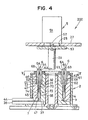
- Fig. 4 is a cross sectional front view of a wire twisting formation apparatus according to an embodiment of the present invention;
- Fig. 5 is a cross sectional plan view taken along a line V-V of Fig. 4;
- Fig. 6 is an enlarged view of a part of Fig. 5;
- Fig. 7 is perspective views of a near letter U shaped wire and a twisted wire;
- Fig. 8 is perspective views of near letter U shaped double wires and twisted double wires;
- Fig. 9 is a cross sectional front view of a wire twisting formation apparatus according to another embodiment of the present invention; and
- Fig. 10 is a partly enlarged view of a conventional apparatus for forming in a twisted shape a near letter U shaped wire.
- Figs. 1 to 3 show a
twisting formation apparatus 100 for forming a near letter U shaped wire in a twisted shape as a stator manufacturing apparatus. - The
twisting formation apparatus 100 is for forming a near letter U shapedwire 10 in a twisted shape as shown in Fig. 7 and manufactures at a time a large amount of the twisted wires 1 as electromagnetic coil elements to be used in a stator for a starter and so on. - The near letter U shaped
wire 10 is made by forming in a near letter U shape a predetermined length of a rectangular cross sectional shaped conductive wire coated by insulating material and composed ofstraight line portions 11, 11' and an arc shaped connecting portion 12 (turning portion). - The near letter U shaped
wire 10 may be a circular or other cross sectional shaped wire and the connectingportion 12 may be formed in, beside the arc shape, a near letter V shape or a near trapezoidal shape. - The
apparatus 100 for forming in a twisted shape the near letter U shaped wires is provided with acasing 2 composed of abase plate 21, and a cylindrical shapedcenter axis tube 22 and anexternal tube 23 both of which have a common center axis and are concentrically fixed to thebase plate 21. Aninside retaining ring 24 and anoutside retaining ring 25 are fastened respectively to upper ends of the center axis andexternal tubes window 26 is provided at a lower end of theexternal tube 23. - A cylindrical shaped inside jig 3 (first holding jig) is slidably fitted to an outside of the
center axis tube 22. A cylindrical shaped outside jig 4 (second holding jig) is located outside theinside jig 3 and is slidably fitted to an inside of theexternal tube 23. An upper end internal circumference of theinside jig 3 is slidably retained by the inside retainingring 24 and an upper end external circumference of theoutside jig 4 is slidably retained by theoutside retaining ring 25. - An
inside holding ring 31 is attached to an upper end surface of theinside jig 3. Theinside jig 3 is provided at an upper external circumference thereof with a diameter-reducedportion 33 having an externalcircumferential step 32 and at a lower end thereof with aflange portion 34. Theinside holding ring 31 is provided with aninside holding portion 35 constituted by rectangular shaped holes arranged in a ring shape, in which one of thestraight line portions 11, 11' of the near letter U shaped wire is inserted. An external circumference of theflange portion 34 abuts an internal circumference surface of theexternal tube 23. Alower side arm 36 extending in a radial direction through the arm-insertingwindow 26 is connected to an external circumference portion of theflange 34. - A lower end surface of the
outside jig 4 is slidably placed on theflange portion 34 and theoutside holding ring 41 is fastened to an upper end surface of theoutside jig 34. Theoutside jig 34 is provided at an upper internal circumference thereof with a diameter-enlargedportion 43 having aninternal circumference step 42. - An
upper side arm 44 extending through the arm-insertingwindow 26 is connected to a lower end of theoutside jig 4. Theoutside holding ring 41 is provided with anoutside holding portion 45 constituted by rectangular shaped holes arranged on a circle, in which the other of thestraight line portions 11, 11' of the near letter U shaped wire is inserted. Theoutside holding portion 45 is faced to and arranged concentrically with the inside holdingportion 35. - A pair of
pillars base plate 21 in a manner that theexternal tube 23 is put between the pair ofpillars upper base plate 27 is fixed horizontally to upper ends of thepillars upper base plate 27 is provided with around hole 28 concentrically with thecenter axis tube 22 and abiasing mechanism 5 urging the near letter U shapedwires 10 with a contraction force. - The biasing mechanism is composed of an expanding and
contracting actuator 51, a movingarm 52 driven to move up and down by theactuator 51 and abiasing disk plate 53 fastened at a lower end of the movingarm 52. Thearm 52 is disposed through theround hole 28. The biasingdisk plate 53 has a size sufficient to come in contact with all of the connectingportions 12 of the near letter U shapedwires 10. - The expanding and
contracting actuator 51 may be an actuator causing a reciprocal up and down movement of thearm 52 by means of a cylinder and a hydraulically or aerodynamically-operated piston, or by means of a combination of a motor and a ball screw. Thebiasing mechanism 5 may be of a type that a weight of thebiasing disk plate 53 is utilized. - Next, an operation method of the twisting
formation apparatus 100 is described. - The respective
straight line portions 11, 11' of the near letter U shapedwires 10 are inserted into all of the respective rectangular holes of the inside and outside holdingportions straight line portions 11, 11' come in contact with the external and internal circumference steps 32 and 42, respectively. - Then, the
arm 52 is moved downwardly so that thebiasing disk plate 53 may be moved down, as shown by a two dots-slash line in Fig. 1, to urge all of the connectingportions 12 of the near letter U shapedwires 10 downwardly in the drawing. As a result, certain contraction forces generates in the entire near letter U shapedwires 10 between the external and internal circumference steps 32 and 42 and thebiasing disk plate 53. - Next, as shown in Fig. 3, the lower and
upper side arms portions 12 of the near letter U shapedwires 10 are fixed to thebiasing disk plate 53 due to the contraction force urged by the biasingdisk plate 53. Therefore, each of the connectingportions 12 is formed in a twisted shape by rotating the lower andupper side arms portion 12 are uniformly deformed centered on a top of the connectingportion 12. - As a plenty of the near letter U shaped
wires 10 are installed in the inside andoutside jigs wires 10 are formed in twisted shapes at a time when the inside andoutside jigs - During the twisting formation process mentioned above, the expanding and
contracting actuator 51 urges downward with a certain biasing force (torque) the connectingportions 12 via thebiasing disk plate 53. Thus, the contraction force is always applied between the connectingportion 12 and the respective leading ends of thestraight line portions portion 12. In other words, when the connectingportion 12 of the near letter U shapedwire 10 is formed in the twisted shape, the height position of the connectingportion 12 becomes lower, as a space between thestraight line portions 11, 11' is expanded more largely. At this time, if the near letter U shapedwire 10 is movable in an axial direction, the respective holding positions of the straight line portions at the inside andoutside jigs portion 12 fluctuates. - The biasing
disk plate 53 is so movable up and down that, as the height position of the connectingportion 12 becomes lower, the biasingdisk plate 53 moves downward to follow the connectingportion 12 and continues to urge the connectingportion 12 with a certain biasing force. Thus, the connectingportion 12 is formed in the twisted shape in a manner that the inside and outside jigs hold thestraight line portions 11, 11' of the near letter U shapedwire 10 always at respective predetermined positions. Therefore, the fluctuation of the twisted shape of the connectingportion 12 may be prevented. - Further, after the twisted wires 1 are inserted into the slots of the stator core, the leading ends of the
straight portions 11, 11' are further formed to bend and, then, each of the leading ends of one of the twisted wires 1 is connected to each of the leading ends of another of the twisted wires 1 to complete the stator coil. In this case, as the respective leading end positions of thestraight line portions 11, 11' are aligned due to the contraction force applied by and between thebiasing disk plat 53 and the external and internal circumference steps 32 and 42, as shown in the present embodiment, it is not necessary to align the respective positions of the leading ends of twisted wires 1, separately, when the respective leading ends are connected to each other. This will result in an easy manufacturing process for connecting the wires. - Furthermore, the twisted wires 1 are assembled to the slots of the stator core arranged in a ring shape around the rotor. As the holding portions (the inside holding
portion 35 and the outside holding portion 45) for holding thestraight line portions 11, 11' of the near letter U shapedwires 10 are arranged on respective concentric circles, the assembly of the twisted wires 1 to the slots, as a next process to the twisting formation process, becomes easy. - Figs. 4 to 6 show an embodiment according to the invention. A
wire twisting apparatus 200 as another stator manufacturing apparatus according to the embodiment is for manufacturing twisteddouble wires 6 by forming at a time in twisted shapes near letter U shaped two wires comprising anoutside wire 6A and aninside wire 6B piled up outside and inside, as shown in Fig. 8. - According to this embodiment, the inside and
outside jigs inside diameter portions - At the middle outside and middle
inside diameter portions straight line portions inside wire 6B toward the connectingportion 63. - The spring type biasing means is composed of movable external and
internal tubes diameter portions coil springs internal tubes - The rectangular shaped holes of the inside and outside holding
portions straight line portions 11, 11' of the near letter U shaped double wires 60. When thestraight line portions 11, 11' of the near letter U shaped double wires 60 are inserted into the inside and outside holdingportions straight portions outside wire 6A come in contact with the external and internal circumference steps 32 and 42 and the leading ends of thestraight portions inside wire 6B come in contact with the movable external andinternal tubes - At the state mentioned above, the lower and
upper side arms portions 64 of theoutside wires 6A are always retained to thebiasing disk plate 53 due to the contraction force urged by the biasingdisk plate 53. Therefore, each of the connectingportions 64 is formed in a twisted shape by rotating the lower andupper side arms portion 64. - Further, similarly to the first described conventional structure, as the height position of the connecting
portion 64 becomes lower, the biasingdisk plate 53 moves downward to follow the connectingportion 64 and continues to urge the connectingportion 64 with a certain biasing force. Therefore, the connectingportion 64 is twisted without the fluctuation of the twisted shape of the connectingportion 64. - The near letter U shaped double wires 60 project on sides of the connecting
portions portions portions portions portions straight line portions portions portions - Further, even if the
biasing disk plate 53 urges the connectingportion 64 of theoutside wire 6A, the leading end of eachstraight portion 62 of theoutside wire 6A is held at a predetermined position in an axial direction of eachstraight line portion 62 by the external orinternal circumference step straight portion 62 can not move in an axial direction thereof, and the eachstraight portion 62 may not be further pushed into the inside or outside holdingportion disk plate 53. Therefore, when the near letter U shaped double wires 60 are formed in the twisted shapes, theoutside wire 6A may be prevented from a damage due to a friction between the eachstraight line portion 62 and the inside or outside holdingportion - On the other hand, when the
inside wire 6B is inserted into the inside andoutside jigs inside wire 6B is put between a lower surface of the connecting portion of theoutside wire 6A and the spring type biasing means 7 and receives a force in a contraction direction therefrom. - However, as a curvature radius of the connecting portion of the
inside wire 6B is smaller than that of the connectingportion 64 of theoutside wire 6A, theinside wire 6B is hardened in a higher degree when theinside wire 6B is bent to form in the letter U shape. Therefore, at the twisting formation process, the twisting of the connectingportion 63 of theinside wire 6B starts at positions more far away from the center thereof, compared with the twisting of the connectingportion 64 of theoutside wire 6A. As a result, after the twisting formation process, the length of theinside wire 6B becomes shorter than that of theoutside wire 6A. - As mentioned above, the leading ends of the
straight line portions inside wire 6B are urged toward the biasingdisk plate 53 by the coil springs 73 and 74 via the movable external andinternal tubes portion 63 of theinside wire 6B is twisted, the movable external andinternal tubes inside wire 6B. Thus, the upper surface of the connectingportion 63 of theinside wire 6B keeps to be pressed against the lower surface of the connectingportion 64 of theoutside wire 6A. Therefore, as theinside wire 6B is also twisted at a state that an axial movement is restricted, no fluctuation of the twisted shape of the connectingportion 63 of theinside wire 6B may be generated. - As a plenty of the near letter U shaped double wires 60 are installed in the inside and
outside jigs outside jigs double wires 6 as shown in Fig. 8 are manufactured at a time. - Further, after the twisted
double wires 6 are inserted into the slots of the stator core, the leading ends of thestraight portions straight line portions double wires 6 exposed out of the respective leading ends of the slots are twisted alternately in the adjacent layers in opposite circumferential directions by a predetermined angle (for example, angle corresponding to 1.5 slots). That is, first and third layers of thestraight line portions straight line portions wires - When the leading ends of the outside and inside
wires wires inside wire 6B becomes shorter than that of theoutside wire 6A at the twisting formation process, original length of theinside wire 6B is primarily set to be longer than that of theoutside wire 6A, as shown in Fig. 4. Thus, at the connecting process, the respective leading ends of the outside and insidewires - Fig. 9 shows a
twisting apparatus 300 as a further stator manufacturing apparatus according to another embodiment of the present invention. The twistingapparatus 300 is composed of abase plate 311, aninside jig 321, anoutside jig 331 and acoil biasing mechanism 340. A cylindrical shapedcenter axis tube 312 and a cylindrical shapedexternal tube 313 positioned concentrically and outside thecenter axis tube 312 are fixed perpendicularly to thebase plate 311. The inside andoutside jigs center axis tube 312 and theexternal tube 313. - On an outer lower side of the
center axis tube 312 and on an inner lower side of theexternal tube 313, provided arestep portions outside jigs external tubes outside jigs - The
inside jig 321 is provided at an upper end surface thereof with aninside holding ring 322. Alower side arm 323 for transmitting rotation torque to theinside jig 321 is connected at a lower portion of theinside jig 321. Adjacent to theinside jig 321, rotatably provided are cylindrical shaped first and second positioning rings 324 and 325 for positioning leadinglower ends wires pin 326 to theinside jig 321 and rotatable together with theinside jig 321. The first and second positioning rings 324 and 325 are connected through a penetrating hole provided in thebase plate 311 to a drive motor (not shown in the drawing) and respectively independently movable in an axial direction (up and down directions in the drawing). - The first and second positioning rings 324 and 325 are provided with
slits 324a and 325a extending in axial directions thereof. Circumferential width of theslit 324a or 325a is same with circumferential thickness of thepin 326 provided at an axially intermediate portion of theinside jig 321 and extending toward an outer diameter side thereof. An engagement of thepin 326 with theslits 324a and 325a enables to transmit the rotation force rendered to theinside jig 321 to the first and second positioning rings 324 and 325. - The axial lengths of the
slits 324a and 325a is long to an extent that thepin 32 does not prevent a movement of the first and second positioning rings 324 and 325 for moving upward the near letter U shaped double wires 60 after finishing the twist formation thereof. - The
outside jig 331 is composed of the similar structure to theinside jig 321. That is, theoutside jig 331 is provided at an upper end surface thereof with anoutside holding ring 332. Anupper side arm 333 for transmitting rotation torque to theoutside jig 331 is connected at a lower portion of theoutside jig 331. Adjacent to theoutside jig 331, rotatably provided are cylindrically shaped third and fourth positioning rings 334 and 335 for positioning leading lower ends 62b and 61b of the other of the outside and insidewires - The third and fourth positioning rings 334 and 335 are connected through a
pin 326 to theoutside jig 331 and rotatable together with theoutside jig 331. The third and fourth positioning rings 334 and 335 are connected through a penetrating hole provided in thebase plate 311 to the drive motor (not shown in the drawing) and respectively independently movable in an axial direction (up and down directions in the drawing). The third and fourth positioning rings 334 and 335 are also provided with slits 334a and 335a extending in axial directions thereof, as are same with the first and second positioning rings 324 and 325. - The
coil biasing mechanism 340 is composed of aninside guide 341, abiasing disk plate 342, aspring 343 and a driving motor (not shown in the drawing). Theinside guide 341 is for guiding an inside diameter portion of theoutside wire 6A after thestraight line portions - The
inside guide 341 is composed of adisk portion 341a having a diameter corresponding to the inside diameter of the near letter U shaped double wires 60 arranged in circle shapes, and ashaft 341b extending perpendicularly from a center of thedisk portion 341a. - The biasing
disk plate 342 is movable up and down along theshaft 341b by a drive motor (not shown in the drawing). Thespring 343 is provided between theinside guide 341 and thebiasing disk plate 342 and urges theinside guide 341 downward. - Next, a method for forming in twisted shapes the near letter U shaped double wires 60 with the stator manufacturing apparatus is described.
- The respective
straight line portions wires coil biasing mechanism 340. - Thus, the
disk plate portion 341a of theinside guide 341 is inserted into the inside diameter portion of the near letter U shaped double wires 60 arranged in ring shapes. Then, the biasingdisk plate 342 further moves down relative to theinside guide 341 so as to come in contact with the top portion of the connectingportion 64 of theoutside wire 6A. On the other hand, the first to fourth positioning rings 324, 325, 334 and 335 move up by means of the drive motor (not shown) to support the lower ends of the near letter U shaped double wires 60, respectively. - Thus, the axial movements of the near letter U shaped double wires 60 are restricted by the biasing
disk plate 342 and the first to fourth positioning rings 324, 325, 334 and 335. In particular, as the drive motor (not shown) controls thebiasing disk plate 342 to keep pressing against the top portion of theoutside wire 6A with a certain torque so that a predetermined contacting force may be applied to theoutside wire 6A. - While the above state is maintained, the connecting
portions wires upper arms outside wire 6A are held at predetermined axial positions. - Similarly to the second embodiment, as the height position of the connecting
portion 64 becomes lower at the twisting formation, the biasingdisk plate 342 moves more downward to follow the connectingportion 64, since thebiasing disk plate 342 continues to press the connectingportion 64 with the certain torque. As a result, the connecting portion is twisted without the twisted shape fluctuation of the connectingportion 64. - On the other hand, a length of the
inside wire 6B after the twisted formation becomes shorter than that of theoutside wire 6A, as mentioned in the second embodiment. To cope with this matter, the driving motor (not shown) controls the second and third positioning rings 325 and 334 supporting the leading ends 61a and 61b of thestraight portions 61 of theinside wire 6B to urge the leading ends 61a and 61b with a certain torque at the twisted formation process. - Thus, the second and third positioning rings 325 and 334 moves upward by a distance corresponding to the distance by which the
inside wire 6B becomes shorter when the connectingportion 63 thereof is twisted. Therefore, as the upper surface of the connectingportion 63 of theinside wire 6B keeps in pressing contact with the lower surface of the connectingportion 64 of theoutside wire 6A. As a result, no twisted shape fluctuations of the connectingportions 63 of theinside wires 6B may generate, as theinside wires 6B are also twisted under the axial movement restriction. - Then, after the near letter U shaped double wires 60 are formed in twisted shapes by the inside and
outside jigs outside wire 6A move upward with a predetermined torque or by a predetermined distance, while thebiasing disk plate 342 urges the connectingportion 64 of theoutside wire 6A. - Through this process, the fluctuation of the leading end positions of the
outside wires 6A, which may have occurred to some extent before the upward movement, may be absorbed so that the leading ends of theoutside wires 6A may be accurately aligned. - In addition, though it serves effectively to align the leading end positions of the
outside wires 6A that thebiasing disk plate 342 urges theoutside wire 6A with the predetermined torque, there may be a case that the positions of the leading ends 62a and 62b are not neatly aligned, in particular, when a frictional force between thestraight portion 62 and the holding portion for holding thestraight portion 62 is large. To this end, the upward movement of the first and fourth positioning rings 324 and 335 supporting the leading ends 62a and 62b causes to align definitely the leading end positions. As a result, the connecting process coming thereafter that the leading ends of the outside and insidewires - Though the above embodiments describe that the connecting portions of the near letter U shaped wires are twisted by rotating the inside and outside jigs in the opposite directions by the same angle, rotating only one of the outside and inside jigs or rotating the jigs in the opposite directions by rotating angles different from each other may be an alternative way. In other words, it may be sufficient to relatively rotate the both jigs so as to the connecting portion of the near letter U shaped wire. However, in case of rotating only one of the jigs, it is necessary to make the biasing disk plate for urging with the predetermined torque the connecting portions of the near letter U shaped wires rotatable. When the one of the jigs is rotated, rotating the biasing disk plate by an angle corresponding to 1/2 rotation angle of the jig makes it possible to twist uniformly both sides of the connecting portion.
- Further, the twisting formation process is described as the case of piling up doubly the outside and inside
wires - Furthermore, the above embodiments describe the case that the stator coil is made by connecting the rectangular cross sectional wires. However, the cross section thereof is not limited to be of the rectangular shape but may be of circular, oval or polygonal shape other than the rectangular shape.
Claims (12)
- A stator manufacturing apparatus for manufacturing a stator by connecting a plurality of twisted wires (1) formed by twisting turning portions (63, 64) of approximately U shaped wires (6), each having first and second straight portions (61, 61') (62, 62') linked by the respective turning portions (63, 64), the approximately U shaped wires comprising at least two kinds of wires (6A and 6B) arranged in pile inside and outside with the turning portions having different curvature radiuses, comprising:a first holding jig (3, 321) in which a first holding portion (35, 322) is arranged for holding the first straight portions (61, 62) of said at least two kinds of wires (6A, 6B);a second holding jig (4, 331) in which a second holding portion (45, 332) is arranged for holding the second straight portions (61', 62') of said at least two kinds of wires (6A, 6B); anda first biasing mechanism (5, 340) for applying an axial compressive stress to the turning portion of the wire (6A) arranged outside and a second biasing mechanism (71-73, 325, 334) for applying an axial compressive stress to the leading ends of the straight portions of the wire (6B) arranged inside, while said first and second holding jigs are relatively moved so that said first straight portions (61, 62) of each of said at least two kinds of wires (6A, 6B) may move more apart from respective said second straight portions (61', 62') of each of at least two kinds of wires to twist said turning portions (63, 64) of each of said at least two kinds of wires.
- A stator manufacturing apparatus according to claim 1, whereinsaid first holding portion (35, 322) is formed for moving together with said first holding jig (3, 321) and supporting a leading end of said one of pair of straight line portions (61) held in said first holding jig (3, 321) at a predetermined position in an axial direction thereof; andsaid second holding portion (45, 332) is formed for moving together with said second holding jig (4, 331) and supporting a leading end of said another of pair of straight line portions (62) held in said second holding jig (4, 331) at a predetermined position in an axial direction thereof,wherein said first and second holding portions support said pair of straight line portions of the wire (6A) arranged outside at respective given positions, when the first biasing mechanism (5, 340) urges said turning portion (64) of the wire (6A) arranged outside.
- A stator manufacturing apparatus according to claim 1 or 2, wherein said first biasing mechanism (5, 340) comprises a biasing disk plate (53), which is fastened at a lower end of a moving arm (52) and has a size sufficient to come in contact with all of the connecting portions (12) of the near letter U shaped wires (10).
- A stator manufacturing apparatus according to claim 1, wherein said first holding jig (3, 321) is provided at an upper external circumference thereof with a diameter-reduced portion having an external circumference step (32).
- A stator manufacturing apparatus according to claim 1, wherein said second holding jig (4, 331) is provided at an upper internal circumference thereof with a diameter-enlarged portion (43) having an internal circumference step (42).
- A stator manufacturing apparatus according to claim 1, wherein said second biasing mechanism (71 to 73, 325, 334) comprises coil springs (73, 74) for urging the inside wire (6B) toward the biasing disk plate (53).
- A stator manufacturing apparatus according to claim 1, characterized by cylindrically shaped first and second positioning rings (324, 325) for moving upward the near letter U shaped double wires (60) after finishing the twist formation.
- A stator manufacturing apparatus according to claim 7, characterized by third and fourth cylindrically shaped positioning rings (334, 335) for positioning leading lower ends (62b, 61b) of outside and inside wires (6A, 6B) and which are connected to the second holding jig (331) and are rotatable together with the second holding jig (331).
- A stator manufacturing method for manufacturing a stator by connecting a plurality of twisted wires (1) formed by twisting turning portions of approximately U shaped wires, each having first and second straight portions linked by the respective turning portions, the approximately U shaped wires comprising at least two kinds of wires (6A and 6B) arranged in pile inside and outside with the turning portions having different curvature radiuses, comprising the steps of:piling up inside and outside said turning portions having different curvature radiuses and moving one of said pair of straight line portions more apart from another of said pair of straight line portions in each of at least two kinds of wires so as to twist all turning portion of each of said at least two kinds of near letter U shaped wires, while urging said turning portions of the outside wires (6A) toward said pair of straight line portions thereof, and urging the leading ends of the straightline portions of the inside wires (6B) towards said straight line portions thereof.
- A stator manufacturing method according to claim 9, further comprising steps of:supporting said pair of straight line portions of the wire (6B) piled up outside at respective predetermined axial positions thereof, when said turning portion (64) of the wire (6A) piled up outside are urged toward said pair of straight line portions thereof.
- A stator manufacturing method according to claims 9 or 10 further comprising steps of:urging respective leading ends of said pair of straight line portions (62) of the wire (6A) piled up outside, after said turning portions (63 and 64) of the plural kinds of near letter U shaped wires piled up each other have been twisted.
- A stator manufacturing method according to any one of claims 9 to 11, further comprising steps of:arranging in a ring shape a plurality of units each of which is constituted by the plural kinds of near letter U shaped wires (6A,6B) piled up each other in such a manner that said pair of straight portions (61 and 62) of the near letter U shaped wires in each of the units are aligned radially, wherein said pair of straight portions in each of the units are moved circumferentially to be more apart from each other so that said turning portions (63 and 64) of each of the units of the near letter U shaped wires may be simultaneously twisted.
Applications Claiming Priority (4)
| Application Number | Priority Date | Filing Date | Title |
|---|---|---|---|
| JP9424699 | 1999-03-31 | ||
| JP9424699 | 1999-03-31 | ||
| JP2000016202A JP3199068B2 (en) | 1999-03-31 | 2000-01-25 | Stator manufacturing equipment |
| JP2000016202 | 2000-01-25 |
Publications (4)
| Publication Number | Publication Date |
|---|---|
| EP1041702A2 EP1041702A2 (en) | 2000-10-04 |
| EP1041702A3 EP1041702A3 (en) | 2000-11-15 |
| EP1041702B1 EP1041702B1 (en) | 2003-07-23 |
| EP1041702B2 true EP1041702B2 (en) | 2007-05-02 |
Family
ID=26435514
Family Applications (1)
| Application Number | Title | Priority Date | Filing Date |
|---|---|---|---|
| EP00105881A Expired - Lifetime EP1041702B2 (en) | 1999-03-31 | 2000-03-20 | Stator manufacturing apparatus for forming wires in twisted shape |
Country Status (5)
| Country | Link |
|---|---|
| US (1) | US6425175B1 (en) |
| EP (1) | EP1041702B2 (en) |
| JP (1) | JP3199068B2 (en) |
| DE (1) | DE60003968T3 (en) |
| ES (1) | ES2204386T5 (en) |
Families Citing this family (40)
| Publication number | Priority date | Publication date | Assignee | Title |
|---|---|---|---|---|
| FR2808939B1 (en) * | 2000-05-11 | 2002-07-12 | Valeo Equip Electr Moteur | MACHINE FOR SHAPING THE HEAD OF A STATOR |
| JP3775349B2 (en) * | 2002-06-03 | 2006-05-17 | 株式会社デンソー | Method of manufacturing stator winding of rotating electrical machine, winding structure, and method of manufacturing winding |
| JP3786058B2 (en) | 2002-06-25 | 2006-06-14 | 株式会社デンソー | Segment sequential joining stator coil of rotating electric machine and method for manufacturing the same |
| JP3783659B2 (en) | 2002-06-25 | 2006-06-07 | 株式会社デンソー | Manufacturing method of segment sequential stator coil of rotating electrical machine |
| US6825475B2 (en) * | 2002-09-19 | 2004-11-30 | Applied Materials Israel, Ltd. | Deflection method and system for use in a charged particle beam column |
| JP3982446B2 (en) * | 2003-04-16 | 2007-09-26 | 株式会社日立製作所 | Manufacturing method of rotating electrical machine |
| JP4539263B2 (en) * | 2003-09-25 | 2010-09-08 | 株式会社デンソー | Motor stator and coil forming method thereof |
| JP3960313B2 (en) | 2004-01-30 | 2007-08-15 | 株式会社デンソー | Coil forming apparatus and coil forming method |
| CN101208852B (en) * | 2005-04-26 | 2012-02-01 | Tm4股份有限公司 | Rectangular wire coil head shaping machine and method thereof |
| FR2896352B1 (en) * | 2006-01-16 | 2014-08-22 | Valeo Equip Electr Moteur | DEVICE FOR RADIALLY TRANSFERRING A STATOR WINDING |
| JP2007282420A (en) * | 2006-04-10 | 2007-10-25 | Denso Corp | Vehicle ac power generator |
| JP4872449B2 (en) * | 2006-05-11 | 2012-02-08 | 株式会社豊田自動織機 | STATOR COIL SETTING METHOD AND SETTING DEVICE, AND ROTARY ELECTRIC MANUFACTURING METHOD |
| JP5392548B2 (en) * | 2009-04-07 | 2014-01-22 | 株式会社デンソー | Coil end forming method and coil end forming apparatus for stator coil |
| KR101704867B1 (en) * | 2011-01-04 | 2017-02-22 | 테크노마틱 에스.피.에이. | Method and fixture for twisting end portions of bar conductors, in particular for bar windings of electric machines |
| ITTO20110199A1 (en) | 2011-03-07 | 2012-09-08 | Atop Spa | APPARATUS AND PROCEDURE FOR THE ALIGNMENT OF CONDUCTORS OF COIL ELEMENTS IN DYNAMO ELECTRIC MACHINES TO PERFORM WELDING OPERATIONS. |
| ITTO20110435A1 (en) | 2011-05-16 | 2012-11-17 | Atop Spa | APPARATUS AND PROCEDURE FOR THE CONSTRUCTION OF REEL ELEMENTS FOR DYNAMIC ELECTRIC MACHINES WITH BENDING. |
| JP5841017B2 (en) * | 2012-07-12 | 2016-01-06 | 本田技研工業株式会社 | Electrical conductor insertion device |
| KR101427466B1 (en) * | 2012-07-16 | 2014-08-07 | 이창열 | Bending device |
| JP6132922B2 (en) * | 2013-09-18 | 2017-05-24 | 本田技研工業株式会社 | Alignment method and alignment apparatus |
| ITPI20130092A1 (en) | 2013-10-18 | 2015-04-19 | Atop Spa | EQUIPMENT AND METHOD TO PRODUCE COMPONENTS OF DYNAMOELECTRIC MACHINES |
| CN103545999B (en) * | 2013-10-31 | 2016-01-13 | 长沙友佳实业有限公司 | Tension-torsion head shaped device is split in the overall doubling of a kind of motor rotor U wire |
| SI3114757T1 (en) | 2014-03-07 | 2019-01-31 | Atop S.P.A. | Apparatus and method for forming coil members |
| DE102014206105B4 (en) * | 2014-04-01 | 2015-11-12 | Continental Automotive Gmbh | Apparatus and method for bending winding segments to form a winding, winding support, electric machine |
| PL3289672T3 (en) | 2015-04-30 | 2019-10-31 | Atop Spa | Methods and apparatuses for forming woven undulated coil assemblies |
| ITUB20152330A1 (en) | 2015-07-20 | 2017-01-20 | Atop Spa | METHOD AND EQUIPMENT FOR INSERT ASSEMBLED ROLLS IN WAVY DRAWERS OF DYNAMOELECTRIC MACHINES |
| DE102015217936A1 (en) * | 2015-09-18 | 2017-03-23 | Continental Automotive Gmbh | Method and one-piece tool assembly for manufacturing a stator for an electric machine |
| DE102015217922A1 (en) * | 2015-09-18 | 2017-03-23 | Continental Automotive Gmbh | Method and two-part tool assembly for manufacturing a stator for an electric machine |
| EP3369161B1 (en) * | 2015-10-26 | 2021-05-26 | DANA TM4 Inc. | Machine for shaping rectangular wire coil heads and method therefor |
| CN108886309B (en) * | 2016-03-22 | 2020-07-24 | 本田技研工业株式会社 | Alignment method and alignment apparatus |
| JP6585826B2 (en) | 2016-03-31 | 2019-10-02 | 日立オートモティブシステムズ株式会社 | Rotating electric machine stator and rotating electric machine using the same |
| JP6305471B2 (en) * | 2016-07-25 | 2018-04-04 | 本田技研工業株式会社 | Stator manufacturing method and apparatus |
| DE102017004538A1 (en) * | 2017-05-11 | 2018-11-15 | Gehring E-Tech Gmbh | Method and device for forming U-shaped electrical conductors |
| DE102018103100A1 (en) | 2017-07-04 | 2019-01-10 | Grob-Werke Gmbh & Co. Kg | Method and device for positioning and clamping wire ends for electrical machines |
| DE102017211937A1 (en) * | 2017-07-12 | 2019-01-17 | Thyssenkrupp Ag | Receiving device for positioning copper rods and assembly plant with receiving device |
| DE102017122506A1 (en) * | 2017-09-27 | 2019-03-28 | Vaf Gmbh | Positioning device for aligning at least one conductor body and method for aligning at least one conductor body by means of a positioning device |
| JP7023185B2 (en) * | 2018-05-22 | 2022-02-21 | 三菱電機株式会社 | Processing equipment for rotary electric machines and processing methods for rotary electric machines |
| AT522207A1 (en) * | 2019-03-01 | 2020-09-15 | Miba Automation Systems Ges M B H | Method and device for forming a conductor package and inserting it into a laminated core |
| DE102019211713A1 (en) * | 2019-08-05 | 2021-02-11 | Zf Friedrichshafen Ag | Twist device and method for a hairpin winding |
| DE102020115248A1 (en) * | 2020-06-09 | 2021-12-09 | Seg Automotive Germany Gmbh | Method for producing a winding for a rotor of an electrical machine |
| CN111822584B (en) * | 2020-07-22 | 2022-02-11 | 芜湖市夯福机械模具有限公司 | Perforating machine for machining automobile parts and capable of achieving accurate positioning through gears |
Citations (1)
| Publication number | Priority date | Publication date | Assignee | Title |
|---|---|---|---|---|
| SU1115170A1 (en) † | 1983-05-31 | 1984-09-23 | Научно-Исследовательский И Экспериментальный Институт Автотракторного Электрооборудования И Автоприборов | Method and apparatus for manufacturing sections of rigid winding and placing these sections in slots of magnetic circuit |
Family Cites Families (47)
| Publication number | Priority date | Publication date | Assignee | Title |
|---|---|---|---|---|
| US1822261A (en) | 1927-06-28 | 1931-09-08 | Vincent G Apple | Bar wound field element |
| US2407935A (en) | 1944-05-25 | 1946-09-17 | Chrysler Corp | Electrical machine |
| US2928963A (en) | 1956-06-06 | 1960-03-15 | Gen Motors Corp | Dynamoelectric machine |
| US3453468A (en) | 1966-09-21 | 1969-07-01 | Kurz & Root Co Inc | Dynamoelectric machine winding arrangement with end turn insulation and method of making the same |
| US3450913A (en) | 1966-12-30 | 1969-06-17 | Lucas Industries Ltd | Interdigitated rotor arrangement for alternator |
| JPS5047102A (en) | 1973-08-23 | 1975-04-26 | ||
| US4238702A (en) | 1978-11-16 | 1980-12-09 | Belova Tamara N | Bar winding of stator of slotless-core electrical machine |
| JPS6053536B2 (en) | 1980-01-09 | 1985-11-26 | 株式会社デンソー | Vehicle alternator |
| ZA836677B (en) | 1982-09-29 | 1984-09-26 | Motorola Inc | Axial air gap brushless alternator |
| JPS5998358A (en) | 1982-11-26 | 1984-06-06 | Seiko Epson Corp | Disk clamp mechanism |
| JPS59159638A (en) | 1983-03-01 | 1984-09-10 | Nippon Denso Co Ltd | Ac generator for vehicle |
| JPS60226755A (en) * | 1984-04-23 | 1985-11-12 | Nippon Denso Co Ltd | Armature and manufacture thereof |
| JPS61221561A (en) | 1985-03-27 | 1986-10-01 | Nippon Denso Co Ltd | Flat rotary electric machine |
| JPH0744797B2 (en) | 1986-05-20 | 1995-05-15 | 日本電装株式会社 | Armature coil |
| DE3704780A1 (en) | 1987-02-16 | 1988-11-10 | Wolfram Wittenborn | System of improvements for electrical machines having an air-cored bell-type armature |
| JPS63257435A (en) | 1987-04-13 | 1988-10-25 | Mitsubishi Electric Corp | Ac generator for rolling stock |
| JPS63274335A (en) | 1987-04-30 | 1988-11-11 | Nippon Denso Co Ltd | Armature coil |
| JPS645340A (en) | 1987-06-25 | 1989-01-10 | Nippon Denso Co | Rotating electric machine |
| DE3901098C1 (en) | 1989-01-16 | 1990-04-12 | Siemens Ag, 1000 Berlin Und 8000 Muenchen, De | Multiphase bar winding for electrical machine - has special crossing rods to connect strands in upper and lower grooves |
| JP2615185B2 (en) | 1989-02-15 | 1997-05-28 | 三菱電機株式会社 | AC generator for vehicles |
| JP2903574B2 (en) | 1989-11-14 | 1999-06-07 | 株式会社デンソー | AC generator for vehicles |
| EP0454039B1 (en) | 1990-04-24 | 1996-10-23 | Nippondenso Co., Ltd. | Alternating current generator having a plurality of independent three-phase windings |
| JP3041884B2 (en) | 1990-05-17 | 2000-05-15 | 株式会社デンソー | AC generator for vehicles |
| DE4031276A1 (en) | 1990-10-04 | 1992-04-09 | Bosch Gmbh Robert | STAND FOR ELECTRICAL MACHINES AND METHOD FOR THE PRODUCTION THEREOF |
| JPH04265653A (en) | 1991-02-18 | 1992-09-21 | Mitsubishi Electric Corp | Armature of dc motor |
| US5363546A (en) | 1992-02-03 | 1994-11-15 | General Electric Company | Apparatus for making armatures for electrodynamic machines |
| US5708316A (en) | 1992-10-23 | 1998-01-13 | Nippondenso Co., Ltd. | Altenator for a vehicle |
| US5691590A (en) | 1992-10-23 | 1997-11-25 | Nippondenso Co., Ltd. | Alternator with magnetic noise reduction mechanism |
| JP3368605B2 (en) | 1992-11-20 | 2003-01-20 | 株式会社デンソー | Stator of vehicle alternator |
| JP3239630B2 (en) | 1993-11-29 | 2001-12-17 | 株式会社デンソー | AC generator for vehicles |
| JP2941636B2 (en) | 1994-03-01 | 1999-08-25 | 株式会社日立製作所 | Vehicle alternator rotor |
| JPH07303351A (en) | 1994-03-11 | 1995-11-14 | Nippondenso Co Ltd | Ac generator for vehicle |
| US5845389A (en) | 1994-06-04 | 1998-12-08 | Northrop Grumman Corporation | Method of fabricating a wound core |
| JP3477962B2 (en) | 1994-12-19 | 2003-12-10 | 株式会社デンソー | Method for manufacturing rotor of rotating electric machine |
| US5778512A (en) | 1994-12-19 | 1998-07-14 | Nippondenso Co., Ltd. | Manufacturing method for a rotor of an electric rotary machine |
| JP3474660B2 (en) | 1995-01-23 | 2003-12-08 | 株式会社日立製作所 | 3 phase motor |
| JPH08298756A (en) | 1995-04-25 | 1996-11-12 | Toyota Motor Corp | Manufacture of stator for motor and stator core |
| JP3458531B2 (en) | 1995-06-02 | 2003-10-20 | 株式会社デンソー | Alternator |
| JP3709582B2 (en) | 1995-08-11 | 2005-10-26 | 株式会社デンソー | Vehicle alternator |
| EP1237254B1 (en) * | 1997-05-26 | 2008-06-04 | Denso Corporation | Alternator for vehicle |
| US5965965A (en) * | 1997-05-26 | 1999-10-12 | Denso Corporation | Stator winding arrangement of alternator for vehicle |
| CA2238504C (en) * | 1997-05-26 | 2001-03-13 | Atsushi Umeda | Stator arrangement of alternator for vehicle |
| WO1998054822A1 (en) * | 1997-05-26 | 1998-12-03 | Denso Corporation | Ac generator for vehicle |
| US5986375A (en) * | 1997-09-26 | 1999-11-16 | Denso Corporation | Alternator for vehicle |
| EP0917278B2 (en) * | 1997-09-26 | 2008-12-31 | Denso Corporation | Alternator for vehicle |
| DE69829229T2 (en) * | 1997-10-16 | 2005-07-21 | Denso Corp., Kariya | Method and apparatus for manufacturing the stator of an alternator for vehicles |
| JP3407675B2 (en) * | 1998-11-26 | 2003-05-19 | 株式会社デンソー | Stator of vehicle alternator and vehicle alternator using the same |
-
2000
- 2000-01-25 JP JP2000016202A patent/JP3199068B2/en not_active Expired - Lifetime
- 2000-03-20 EP EP00105881A patent/EP1041702B2/en not_active Expired - Lifetime
- 2000-03-20 ES ES00105881T patent/ES2204386T5/en not_active Expired - Lifetime
- 2000-03-20 DE DE60003968T patent/DE60003968T3/en not_active Expired - Lifetime
- 2000-03-31 US US09/542,022 patent/US6425175B1/en not_active Expired - Lifetime
Patent Citations (1)
| Publication number | Priority date | Publication date | Assignee | Title |
|---|---|---|---|---|
| SU1115170A1 (en) † | 1983-05-31 | 1984-09-23 | Научно-Исследовательский И Экспериментальный Институт Автотракторного Электрооборудования И Автоприборов | Method and apparatus for manufacturing sections of rigid winding and placing these sections in slots of magnetic circuit |
Also Published As
| Publication number | Publication date |
|---|---|
| JP3199068B2 (en) | 2001-08-13 |
| ES2204386T5 (en) | 2007-12-01 |
| US6425175B1 (en) | 2002-07-30 |
| ES2204386T3 (en) | 2004-05-01 |
| DE60003968D1 (en) | 2003-08-28 |
| EP1041702A2 (en) | 2000-10-04 |
| EP1041702A3 (en) | 2000-11-15 |
| JP2000343137A (en) | 2000-12-12 |
| EP1041702B1 (en) | 2003-07-23 |
| DE60003968T3 (en) | 2007-09-20 |
| DE60003968T2 (en) | 2004-03-04 |
Similar Documents
| Publication | Publication Date | Title |
|---|---|---|
| EP1041702B2 (en) | Stator manufacturing apparatus for forming wires in twisted shape | |
| JP3960313B2 (en) | Coil forming apparatus and coil forming method | |
| JPS5936503B2 (en) | Winding core forming method and forming device | |
| US6314780B1 (en) | Method of manufacturing conductor segments of AC generator | |
| WO2016129197A1 (en) | Stator assembling method and stator assembling device | |
| JP3988303B2 (en) | Stator manufacturing method and manufacturing apparatus thereof | |
| EP1304789B1 (en) | Apparatus and method for forming winding heads in dynamo-electric machine cores | |
| JP4214469B2 (en) | Segment conductor alignment method and alignment apparatus | |
| JP7450414B2 (en) | Stator manufacturing method and manufacturing equipment | |
| KR20220162291A (en) | Widing device of hair pin type stator coil | |
| JP5251625B2 (en) | Bending machine | |
| EP0162317B1 (en) | Armatures and method for manufacturing such armatures | |
| JP7068012B2 (en) | Manufacturing method and manufacturing equipment for rotary electric stator | |
| US4541170A (en) | Method and device for forming the rotor winding coils of a dynamoelectric machine | |
| KR102684618B1 (en) | Winding Equipment for Connection Type Stator Core | |
| EP0119172B1 (en) | Device for forming the rotor winding coils of a dynamoelectric machine and for anchoring the ends of the coils to a commutator associated with the rotor | |
| CN210142970U (en) | Skew correction device for stator | |
| JP4648716B2 (en) | Laminated iron core and manufacturing method thereof | |
| JP7255225B2 (en) | How to assemble the stator | |
| KR20220033238A (en) | Zig apparatus for hairpin alignment | |
| JPS6314575B2 (en) | ||
| KR20240000351A (en) | Hair pin bending and expansion device for hair pin motor | |
| US5628500A (en) | Clamping apparatus for a coil | |
| CN113452221B (en) | Coil inserting device | |
| WO2022003998A1 (en) | Wedge insertion device and coil insertion device |
Legal Events
| Date | Code | Title | Description |
|---|---|---|---|
| PUAI | Public reference made under article 153(3) epc to a published international application that has entered the european phase |
Free format text: ORIGINAL CODE: 0009012 |
|
| PUAL | Search report despatched |
Free format text: ORIGINAL CODE: 0009013 |
|
| AK | Designated contracting states |
Kind code of ref document: A2 Designated state(s): DE ES FR GB IT |
|
| AX | Request for extension of the european patent |
Free format text: AL;LT;LV;MK;RO;SI |
|
| AK | Designated contracting states |
Kind code of ref document: A3 Designated state(s): AT BE CH CY DE DK ES FI FR GB GR IE IT LI LU MC NL PT SE |
|
| AX | Request for extension of the european patent |
Free format text: AL;LT;LV;MK;RO;SI |
|
| 17P | Request for examination filed |
Effective date: 20001130 |
|
| AKX | Designation fees paid |
Free format text: DE ES FR GB IT |
|
| 17Q | First examination report despatched |
Effective date: 20020528 |
|
| GRAH | Despatch of communication of intention to grant a patent |
Free format text: ORIGINAL CODE: EPIDOS IGRA |
|
| GRAH | Despatch of communication of intention to grant a patent |
Free format text: ORIGINAL CODE: EPIDOS IGRA |
|
| GRAA | (expected) grant |
Free format text: ORIGINAL CODE: 0009210 |
|
| AK | Designated contracting states |
Designated state(s): DE ES FR GB IT |
|
| REG | Reference to a national code |
Ref country code: GB Ref legal event code: FG4D |
|
| REF | Corresponds to: |
Ref document number: 60003968 Country of ref document: DE Date of ref document: 20030828 Kind code of ref document: P |
|
| ET | Fr: translation filed | ||
| PLBQ | Unpublished change to opponent data |
Free format text: ORIGINAL CODE: EPIDOS OPPO |
|
| PLBI | Opposition filed |
Free format text: ORIGINAL CODE: 0009260 |
|
| REG | Reference to a national code |
Ref country code: ES Ref legal event code: FG2A Ref document number: 2204386 Country of ref document: ES Kind code of ref document: T3 |
|
| PLAX | Notice of opposition and request to file observation + time limit sent |
Free format text: ORIGINAL CODE: EPIDOSNOBS2 |
|
| 26 | Opposition filed |
Opponent name: VALEO EQUIPEMENTS ELECTRIQUES MOTEUR Effective date: 20040423 |
|
| PLAX | Notice of opposition and request to file observation + time limit sent |
Free format text: ORIGINAL CODE: EPIDOSNOBS2 |
|
| PLAX | Notice of opposition and request to file observation + time limit sent |
Free format text: ORIGINAL CODE: EPIDOSNOBS2 |
|
| PLBB | Reply of patent proprietor to notice(s) of opposition received |
Free format text: ORIGINAL CODE: EPIDOSNOBS3 |
|
| PLAB | Opposition data, opponent's data or that of the opponent's representative modified |
Free format text: ORIGINAL CODE: 0009299OPPO |
|
| R26 | Opposition filed (corrected) |
Opponent name: VALEO EQUIPEMENTS ELECTRIQUES MOTEUR Effective date: 20040423 |
|
| PUAH | Patent maintained in amended form |
Free format text: ORIGINAL CODE: 0009272 |
|
| STAA | Information on the status of an ep patent application or granted ep patent |
Free format text: STATUS: PATENT MAINTAINED AS AMENDED |
|
| 27A | Patent maintained in amended form |
Effective date: 20070502 |
|
| AK | Designated contracting states |
Kind code of ref document: B2 Designated state(s): DE ES FR GB IT |
|
| ET3 | Fr: translation filed ** decision concerning opposition | ||
| REG | Reference to a national code |
Ref country code: ES Ref legal event code: DC2A Date of ref document: 20070718 Kind code of ref document: T5 |
|
| REG | Reference to a national code |
Ref country code: FR Ref legal event code: PLFP Year of fee payment: 17 |
|
| REG | Reference to a national code |
Ref country code: FR Ref legal event code: PLFP Year of fee payment: 18 |
|
| REG | Reference to a national code |
Ref country code: FR Ref legal event code: PLFP Year of fee payment: 19 |
|
| PGFP | Annual fee paid to national office [announced via postgrant information from national office to epo] |
Ref country code: IT Payment date: 20190325 Year of fee payment: 20 Ref country code: DE Payment date: 20190321 Year of fee payment: 20 Ref country code: GB Payment date: 20190320 Year of fee payment: 20 Ref country code: FR Payment date: 20190322 Year of fee payment: 20 |
|
| PGFP | Annual fee paid to national office [announced via postgrant information from national office to epo] |
Ref country code: ES Payment date: 20190418 Year of fee payment: 20 |
|
| REG | Reference to a national code |
Ref country code: DE Ref legal event code: R071 Ref document number: 60003968 Country of ref document: DE |
|
| REG | Reference to a national code |
Ref country code: GB Ref legal event code: PE20 Expiry date: 20200319 |
|
| PG25 | Lapsed in a contracting state [announced via postgrant information from national office to epo] |
Ref country code: GB Free format text: LAPSE BECAUSE OF EXPIRATION OF PROTECTION Effective date: 20200319 |
|
| REG | Reference to a national code |
Ref country code: ES Ref legal event code: FD2A Effective date: 20220105 |
|
| PG25 | Lapsed in a contracting state [announced via postgrant information from national office to epo] |
Ref country code: ES Free format text: LAPSE BECAUSE OF EXPIRATION OF PROTECTION Effective date: 20200321 |