EP1041602A2 - Cooling system for a dielectric-barrier discharge lamp - Google Patents
Cooling system for a dielectric-barrier discharge lamp Download PDFInfo
- Publication number
- EP1041602A2 EP1041602A2 EP00106471A EP00106471A EP1041602A2 EP 1041602 A2 EP1041602 A2 EP 1041602A2 EP 00106471 A EP00106471 A EP 00106471A EP 00106471 A EP00106471 A EP 00106471A EP 1041602 A2 EP1041602 A2 EP 1041602A2
- Authority
- EP
- European Patent Office
- Prior art keywords
- dielectric
- discharge lamp
- barrier discharge
- tube
- lamp device
- Prior art date
- Legal status (The legal status is an assumption and is not a legal conclusion. Google has not performed a legal analysis and makes no representation as to the accuracy of the status listed.)
- Withdrawn
Links
Images

Classifications
-
- H—ELECTRICITY
- H01—ELECTRIC ELEMENTS
- H01J—ELECTRIC DISCHARGE TUBES OR DISCHARGE LAMPS
- H01J61/00—Gas-discharge or vapour-discharge lamps
- H01J61/02—Details
- H01J61/52—Cooling arrangements; Heating arrangements; Means for circulating gas or vapour within the discharge space
-
- H—ELECTRICITY
- H01—ELECTRIC ELEMENTS
- H01J—ELECTRIC DISCHARGE TUBES OR DISCHARGE LAMPS
- H01J65/00—Lamps without any electrode inside the vessel; Lamps with at least one main electrode outside the vessel
- H01J65/04—Lamps in which a gas filling is excited to luminesce by an external electromagnetic field or by external corpuscular radiation, e.g. for indicating plasma display panels
- H01J65/042—Lamps in which a gas filling is excited to luminesce by an external electromagnetic field or by external corpuscular radiation, e.g. for indicating plasma display panels by an external electromagnetic field
- H01J65/046—Lamps in which a gas filling is excited to luminesce by an external electromagnetic field or by external corpuscular radiation, e.g. for indicating plasma display panels by an external electromagnetic field the field being produced by using capacitive means around the vessel
Definitions
- This invention concerns a dielectric-barrier discharge lamp device.
- the lamps conventionally used to provide such treatment have been low-pressure mercury lamps that emit vacuum ultraviolet radiation at a wavelength of 185 nm, which is the resonant line of mercury.
- dielectric-barrier discharge lamps have come to be used. These are lamps that produce excimer emissions by containing a gas for excimer emissions in a discharge vessel made up of a dielectric and bringing about a dielectric-barrier discharge (also called "ozonizer discharge” or "silent discharge.” See Discharge Handbook , Association of Electrical Studies, rev. ed. June 1989, p. 263).
- Such dielectric-barrier discharge lamps are described in, for example, U.S. Patent No. 4,945,290 (Japanese Kokai Patent H1-144560). That patent document describes a dielectric-barrier discharge lamp in which a hollow-cylinder-shaped discharge space, made up of quartz glass of which at least a part is dielectric, is filled with a gas for excimer emissions.
- a problem of dielectric-barrier discharge lamps of that type is that the lighting efficiency of the lamp (the ratio of area lighted to input power) decreases as the power input to the lamp is increased.
- the cause is thought to be that the temperature of the gas in the lamp increases with the input power, and the lighting efficiency decreases as a result.
- the transmissivity at a wavelength of 172 nm is about 85% at 25°C, but it falls to about 83% at 100°C and about 73% at 300°C.
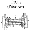
- FIG. 3 is an explanatory drawing of a conventional dielectric-barrier discharge lamp device fitted with a cooling mechanism.
- the discharge lamp 1 has two coaxial tubes, an inner tube 2 and an outer tube 3, forming a hollow-cylinder-shaped discharge space 4 between the inner tube 2 and the outer tube 3.
- the inner tube 2 and the outer tube 3 are made up of a dielectric, at least in part.
- the inner tube 2 and the outer tube 3 are made up of quartz glass that allows light at a wavelength of 172 nm to pass.
- a roughly cylindrical electrode 5 is placed in close contact with the inner surface of inner tube 2.
- This internal electrode 5 is made up by joining two half cylinders formed by bending aluminum sheets.
- an external electrode 6 Around the outer surface of the outer tube 3 is placed an external electrode 6 that allows the light to pass through it.
- the external electrode 6 comprises a mesh electrode that allows the passage of ultraviolet light.
- the internal electrode 5 and external electrode 6 are connected to an alternating current power supply that is not illustrated.
- An inert gas or a mixture of an inert gas and a halogen is placed in the discharge space 4 as a discharge gas.
- a ring-shaped gasket 7 is located that has a through-hole 7A and that is aligned with the end 1A, 1B of lamp 1.
- the diameter of the through-holes 7A is the same as the diameter of the inner space P that is formed by the inner tube 2.
- a coupler fitting 8 has the gasket 7 on its inner face; by rotating this coupler fitting 8, the gaskets 7 are pressed against the ends 1A, 1B of the dielectric-barrier discharge lamp 1, creating a tight seal between the gaskets 7 and the ends 1A, 1B.
- Through-holes 8A are formed in the coupler fittings 8 to align with the through-holes 7A in the gaskets 7.
- the coupler fittings 8 are held in casings 9 by O-rings 10.
- This casing 9 is formed with through-holes 9A aligned to allow the passage of a coolant fluid through through-holes 8A.
- the inner space P formed by the inner tube 2 forms a passage along with the through-holes 8A of the coupler fittings 8 and the through-holes 9A of the casing 9.
- the coolant fluid leaving one side of the casing 9 through through-hole 9A then passes through the through-holes 8A and 7A into the inner space P formed by the inner tube 2, to cool the dielectric-baffler discharge lamp 1 from the inner tube 2.
- the dielectric-baffler discharge lamp 1 is made by welding together the inner tube 2 and the outer tube 3 in order to form the discharge space 4. For that reason, there will be irregularities where the ends 1A, 1B face gaskets 7. That is, when the gaskets 7 are pushed tightly against the ends 1A, 1B, gaps may be left between the gaskets 7 and the ends 1A, 1B if they are not pushed hard enough, and the coolant fluid is liable to leak from those gaps. Also, there is the problem that, if the coolant fluid leaks, it will not be possible to cool the dielectric-barrier discharge lamp 1.
- vacuum ultraviolet radiation is emitted by the dielectric-barrier discharge lamp 1, and the gaskets 7 are directly illuminated by that vacuum ultraviolet radiation.
- the gaskets 7 deteriorate because of the vacuum ultraviolet radiation.
- gaps occur between the gaskets 7 and the ends 1A, 1B in the course of deterioration of the gaskets 7, causing leakage of the coolant fluid from the gaps.
- a primary object of this invention is to provide a dielectric-barrier discharge lamp device in which leakage of the coolant fluid used to cool the dielectric-barrier discharge lamp can be reliably prevented, and in which the dielectric-barrier discharge lamp can be reliably cooled.
- this invention provides a dielectric-barrier discharge lamp device having a dielectric-barrier discharge lamp with a hollow-cylinder-shaped discharge space formed by an outer tube that is roughly cylindrical in external shape and a co-axial inner tube, in which the inner tube has a cylindrical tube extension that extends outward from the discharge space, and in which the outer periphery of the end of the tube extension is held tightly by a coupler fitting connected to a guide tube through which a coolant fluid flows.
- a dielectric-barrier discharge lamp device 1 in accordance with the present invention which comprises a co-axial, overlapping structure of an inner tube 2 and an outer tube 3 made of quartz glass, a dielectric that passes light with a wavelength of 172 nm.
- the ends of the inner tube 2 and the outer tube 3 are welded together to form a hollow-cylinder-shaped discharge space 4.
- the inner space P formed by the inner tube 2 has a diameter of 12 to 15 mm, the thickness of the inner tube 2 is 1 mm, the outer diameter of the outer tube 3 is 24 to 27 mm, and the thickness of the outer tube 3 is 1 mm.
- the length of the discharge space 4 is 260 mm, and the discharge space 4 is filled with xenon, as an inert gas, at a pressure of 3 to 5 KPa.
- a part of the inner tube 2 forms a cylindrical tube extension 2A that projects beyond the discharge space 4 formed by the inner tube 2 and the outer tube 3. That is, the central space 2P of tube extension 2A connects with the inner space P.
- the tube extension 2A comprises a part of the inner tube 2; but it may also be a separate piece welded to the end 1A or 1B of the inner tube 2 in the direction of the axis of the dielectric-barrier discharge lamp 1, such that its central space connects with the inner space P.
- a roughly cylindrical electrode 5 is closely adhered to the inner surface of the inner tube 2.
- This internal electrode 5 can be formed, for example, by joining two half cylinders made by bending aluminum sheet 0.5 mm thick.
- an external electrode 6 Around the outer surface of the outer tube 3 is placed an external electrode 6 that allows the light to pass through.
- This external electrode 6 comprises a mesh electrode that allows the passage of ultraviolet light.
- the internal electrode 5 and external electrode 6 are connected to an alternating current power supply (not illustrated).
- the end 2A1 of the tube extension 2A is attached to a coupler fitting 8, which connects to a guide tube 11 through which the coolant fluid flows. Specifically, the outer periphery of the end 2A1 is held tightly by the coupler fitting 8.
- the coupler fitting 8 that attaches to the other tube extension 2A is not shown but is the same in construction.
- the guide tube 11 is an inlet or outlet tube for the coolant fluid, and either projects from or is contained in the casing that holds the dielectric-barrier discharge lamp 1 in place.
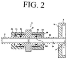
- FIG. 2 is an enlarged view showing the relationship between the tube extension 2A and the coupler fitting 8.
- the coupler fitting 8 comprises a stainless steel body 81, fluorine polymer O-rings 82, iron-nickel alloy ferrules 83 and stainless steel cap nuts 84. This coupler fitting 8 connects the tube extension 2A to the guide tube 11 through which the coolant fluid flows.
- the method of connecting the tube extension 2A and the coupler fitting 8 is as follows.
- the cap nut 84 is placed on the tube extension 2A in advance, and then the ferrule 83 is placed on the tube extension 2A so as to fit into the front of the cap nut 84.
- the O-ring 82 is placed in front of the ferrule 83 so that it is in contact with the entire circumference of the tube extension 2A, after which the end 2A1 of the tube extension 2A is slid into the body 81 to which the guide tube 11 is connected.
- the cap nut 84 is pushed onto the body 81 and rotated so that the threads of the cap nut 84 engage the threads of the body 81.
- the O-ring 82 is deformed to create a tight fit between body 81 and ferrule 83, providing a tight hold on the outer periphery of the end 2A1 of the tube extension 2A.
- this is a structure in which the coupler fitting 8 holds tightly to the very smooth surface of the tube extension 2A that connects to the inner space P, it is possible to reliably prevent leakage of the coolant fluid used to cool the dielectric-barrier discharge lamp 1, and to reliably cool the dielectric-barrier discharge lamp 1.
- the fluorine polymer O-ring 82 is completely enclosed by the stainless steel body 81, the iron-nickel alloy ferrule 83 and stainless steel cap nut 84. Therefore, the O-ring 2 is not directly illuminated by the vacuum ultraviolet radiation, which makes it possible to prevent deterioration of the O-ring 82 due to vacuum ultraviolet radiation. As a result, it is possible to prevent, over a long period, the leakage of the coolant fluid that cools the dielectric-barrier discharge lamp 1.
- the coupler fitting 8 is located on the tube extension 2A such that it is separated from the nearest end 1A by a distance L of, e.g., 10 mm, as shown.
- L e.g. 10 mm
- the fixed space L is left between the coupler fitting 8 and the end 1A of the discharge space 4 of the dielectric-barrier discharge lamp 1 that is nearest to the coupler fitting 8.
- the minimum distance between the coupler fitting 8 and the end 1A that forms the discharge space 4 be at least 0.2 mm/W. If this distance is less than 0.2 mm/W, there is an increased possibility that the coupler fitting 8 and the end 1A that forms the discharge space 4 will be too close, thus causing the problems described above.
- this invention provides a dielectric-barrier discharge lamp device having a dielectric-barrier discharge lamp with a hollow-cylinder-shaped discharge space formed by an outer tube that is roughly cylindrical in external shape and a co-axial inner tube, in which the inner tube has a cylindrical tube extension that extends outward from the discharge space, and in which the outer periphery of the end of the tube extension is held tightly by a coupler fitting connected to a guide tube through which a coolant fluid flows.
- the invention provides a dielectric-barrier discharge lamp device that can reliably prevent leakage of the coolant fluid used to cool the dielectric-barrier discharge lamp, and that can reliably cool the dielectric-barrier discharge lamp.
Landscapes
- Physics & Mathematics (AREA)
- Electromagnetism (AREA)
- Engineering & Computer Science (AREA)
- Plasma & Fusion (AREA)
- Discharge Lamps And Accessories Thereof (AREA)
- Vessels And Coating Films For Discharge Lamps (AREA)
- Common Detailed Techniques For Electron Tubes Or Discharge Tubes (AREA)
Abstract
Description
- This invention concerns a dielectric-barrier discharge lamp device.
- In recent years, technology has developed for treating metals, glass and other materials by illuminating the item to be treated with vacuum ultraviolet radiation at wavelengths up to 200 nm, thus allowing the vacuum ultraviolet radiation and the ozone produced thereby to operate on the item to be treated. Examples are cleaning treatment technology that removes organic pollutants adhered to the surface of the item to be treated, and oxide film formation technology that forms an oxide film on the surface of the item to be treated.
- The lamps conventionally used to provide such treatment have been low-pressure mercury lamps that emit vacuum ultraviolet radiation at a wavelength of 185 nm, which is the resonant line of mercury. In recent times, dielectric-barrier discharge lamps have come to be used. These are lamps that produce excimer emissions by containing a gas for excimer emissions in a discharge vessel made up of a dielectric and bringing about a dielectric-barrier discharge (also called "ozonizer discharge" or "silent discharge." See Discharge Handbook, Association of Electrical Studies, rev. ed. June 1989, p. 263).
- Such dielectric-barrier discharge lamps are described in, for example, U.S. Patent No. 4,945,290 (Japanese Kokai Patent H1-144560). That patent document describes a dielectric-barrier discharge lamp in which a hollow-cylinder-shaped discharge space, made up of quartz glass of which at least a part is dielectric, is filled with a gas for excimer emissions.
- A problem of dielectric-barrier discharge lamps of that type is that the lighting efficiency of the lamp (the ratio of area lighted to input power) decreases as the power input to the lamp is increased. The cause is thought to be that the temperature of the gas in the lamp increases with the input power, and the lighting efficiency decreases as a result.
- There is an additional problem in that the increase of gas temperature decreases the transmissivity of the quartz glass. For example, the transmissivity at a wavelength of 172 nm is about 85% at 25°C, but it falls to about 83% at 100°C and about 73% at 300°C.
- There is a further problem in that the increased temperature of the lamp lowers the insulator fracture voltage of the quartz glass, and so it is possible for the lamp to fracture and leak. Depending on the application, it is often necessary to increase the input power in order to raise the light output. For that reason, it becomes necessary to reduce the gas temperature by cooling the lamp itself.
- Figure 3 is an explanatory drawing of a conventional dielectric-barrier discharge lamp device fitted with a cooling mechanism. In the drawing, the
discharge lamp 1 has two coaxial tubes, aninner tube 2 and anouter tube 3, forming a hollow-cylinder-shaped discharge space 4 between theinner tube 2 and theouter tube 3. Theinner tube 2 and theouter tube 3 are made up of a dielectric, at least in part. For example, theinner tube 2 and theouter tube 3 are made up of quartz glass that allows light at a wavelength of 172 nm to pass. - A roughly
cylindrical electrode 5 is placed in close contact with the inner surface ofinner tube 2. Thisinternal electrode 5 is made up by joining two half cylinders formed by bending aluminum sheets. Around the outer surface of theouter tube 3 is placed anexternal electrode 6 that allows the light to pass through it. Theexternal electrode 6 comprises a mesh electrode that allows the passage of ultraviolet light. Theinternal electrode 5 andexternal electrode 6 are connected to an alternating current power supply that is not illustrated. An inert gas or a mixture of an inert gas and a halogen is placed in thedischarge space 4 as a discharge gas. - At each of the ends 1A and 1B of the dielectric-
barrier discharge lamp 1, a ring-shaped gasket 7 is located that has a through-hole 7A and that is aligned with the end 1A, 1B oflamp 1. The diameter of the through-holes 7A is the same as the diameter of the inner space P that is formed by theinner tube 2. - A
coupler fitting 8 has thegasket 7 on its inner face; by rotating this coupler fitting 8, thegaskets 7 are pressed against the ends 1A, 1B of the dielectric-barrier discharge lamp 1, creating a tight seal between thegaskets 7 and the ends 1A, 1B. Through-holes 8A are formed in thecoupler fittings 8 to align with the through-holes 7A in thegaskets 7. - The
coupler fittings 8 are held incasings 9 by O-rings 10. Thiscasing 9 is formed with through-holes 9A aligned to allow the passage of a coolant fluid through through-holes 8A. - In other words, the inner space P formed by the
inner tube 2 forms a passage along with the through-holes 8A of thecoupler fittings 8 and the through-holes 9A of thecasing 9. As indicated by the arrows in Fig, 3, the coolant fluid leaving one side of thecasing 9 through through-hole 9A then passes through the through-holes inner tube 2, to cool the dielectric-baffler discharge lamp 1 from theinner tube 2. - However, the dielectric-
baffler discharge lamp 1 is made by welding together theinner tube 2 and theouter tube 3 in order to form thedischarge space 4. For that reason, there will be irregularities where the ends 1A,1B face gaskets 7. That is, when thegaskets 7 are pushed tightly against the ends 1A, 1B, gaps may be left between thegaskets 7 and the ends 1A, 1B if they are not pushed hard enough, and the coolant fluid is liable to leak from those gaps. Also, there is the problem that, if the coolant fluid leaks, it will not be possible to cool the dielectric-barrier discharge lamp 1. - Moreover, vacuum ultraviolet radiation is emitted by the dielectric-
barrier discharge lamp 1, and thegaskets 7 are directly illuminated by that vacuum ultraviolet radiation. As a result, there is also the problem that thegaskets 7 deteriorate because of the vacuum ultraviolet radiation. In addition, gaps occur between thegaskets 7 and the ends 1A, 1B in the course of deterioration of thegaskets 7, causing leakage of the coolant fluid from the gaps. Thus, there is a problem in that it becomes impossible to cool the dielectric-barrier discharge lamp 1 if the coolant fluid leaks. - A primary object of this invention is to provide a dielectric-barrier discharge lamp device in which leakage of the coolant fluid used to cool the dielectric-barrier discharge lamp can be reliably prevented, and in which the dielectric-barrier discharge lamp can be reliably cooled.
- To achieve the object stated above, this invention provides a dielectric-barrier discharge lamp device having a dielectric-barrier discharge lamp with a hollow-cylinder-shaped discharge space formed by an outer tube that is roughly cylindrical in external shape and a co-axial inner tube, in which the inner tube has a cylindrical tube extension that extends outward from the discharge space, and in which the outer periphery of the end of the tube extension is held tightly by a coupler fitting connected to a guide tube through which a coolant fluid flows.
-
- Fig. 1 is a cross-sectional view of the dielectric-barrier discharge lamp device of this invention;
- Fig. 2 An enlarged cross-sectional view of the coupler fitting of the dielectric-barrier discharge lamp device of this invention; and
- Fig. 3 A cross-sectional view of a conventional dielectric-barrier discharge lamp device.
-
- In Fig. 1, a dielectric-barrier
discharge lamp device 1 in accordance with the present invention is shown which comprises a co-axial, overlapping structure of aninner tube 2 and anouter tube 3 made of quartz glass, a dielectric that passes light with a wavelength of 172 nm. The ends of theinner tube 2 and theouter tube 3 are welded together to form a hollow-cylinder-shaped discharge space 4. - As for physical dimensions, the inner space P formed by the
inner tube 2 has a diameter of 12 to 15 mm, the thickness of theinner tube 2 is 1 mm, the outer diameter of theouter tube 3 is 24 to 27 mm, and the thickness of theouter tube 3 is 1 mm. The length of thedischarge space 4 is 260 mm, and thedischarge space 4 is filled with xenon, as an inert gas, at a pressure of 3 to 5 KPa. - A part of the
inner tube 2 forms acylindrical tube extension 2A that projects beyond thedischarge space 4 formed by theinner tube 2 and theouter tube 3. That is, thecentral space 2P oftube extension 2A connects with the inner space P. Here, thetube extension 2A comprises a part of theinner tube 2; but it may also be a separate piece welded to the end 1A or 1B of theinner tube 2 in the direction of the axis of the dielectric-barrier discharge lamp 1, such that its central space connects with the inner space P. - A roughly
cylindrical electrode 5 is closely adhered to the inner surface of theinner tube 2. Thisinternal electrode 5 can be formed, for example, by joining two half cylinders made by bending aluminum sheet 0.5 mm thick. Around the outer surface of theouter tube 3 is placed anexternal electrode 6 that allows the light to pass through. Thisexternal electrode 6 comprises a mesh electrode that allows the passage of ultraviolet light. Theinternal electrode 5 andexternal electrode 6 are connected to an alternating current power supply (not illustrated). - The end 2A1 of the
tube extension 2A is attached to acoupler fitting 8, which connects to a guide tube 11 through which the coolant fluid flows. Specifically, the outer periphery of the end 2A1 is held tightly by thecoupler fitting 8. Thecoupler fitting 8 that attaches to theother tube extension 2A is not shown but is the same in construction. The guide tube 11 is an inlet or outlet tube for the coolant fluid, and either projects from or is contained in the casing that holds the dielectric-barrier discharge lamp 1 in place. - Figure 2 is an enlarged view showing the relationship between the
tube extension 2A and thecoupler fitting 8. Thecoupler fitting 8 comprises a stainless steel body 81, fluorine polymer O-rings 82, iron-nickel alloy ferrules 83 and stainless steel cap nuts 84. This coupler fitting 8 connects thetube extension 2A to the guide tube 11 through which the coolant fluid flows. - The method of connecting the
tube extension 2A and thecoupler fitting 8 is as follows. Thecap nut 84 is placed on thetube extension 2A in advance, and then theferrule 83 is placed on thetube extension 2A so as to fit into the front of thecap nut 84. Then, the O-ring 82 is placed in front of theferrule 83 so that it is in contact with the entire circumference of thetube extension 2A, after which the end 2A1 of thetube extension 2A is slid into the body 81 to which the guide tube 11 is connected. At this point, thecap nut 84 is pushed onto the body 81 and rotated so that the threads of thecap nut 84 engage the threads of the body 81. Thus, the O-ring 82 is deformed to create a tight fit between body 81 andferrule 83, providing a tight hold on the outer periphery of the end 2A1 of thetube extension 2A. - In other words, because this is a structure in which the
coupler fitting 8 holds tightly to the very smooth surface of thetube extension 2A that connects to the inner space P, it is possible to reliably prevent leakage of the coolant fluid used to cool the dielectric-barrier discharge lamp 1, and to reliably cool the dielectric-barrier discharge lamp 1. - The fluorine polymer O-
ring 82 is completely enclosed by the stainless steel body 81, the iron-nickel alloy ferrule 83 and stainlesssteel cap nut 84. Therefore, the O-ring 2 is not directly illuminated by the vacuum ultraviolet radiation, which makes it possible to prevent deterioration of the O-ring 82 due to vacuum ultraviolet radiation. As a result, it is possible to prevent, over a long period, the leakage of the coolant fluid that cools the dielectric-barrier discharge lamp 1. - As shown in Fig. 1, the
coupler fitting 8 is located on thetube extension 2A such that it is separated from the nearest end 1A by a distance L of, e.g., 10 mm, as shown. The reasons for leaving this space between thecoupler fitting 8 and the end 1A of thedischarge space 4 nearest to thecoupler fitting 8 are as follows: - (1) The
cap nut 84 and body 81 that make up thecoupler fitting 8 are metal parts, and if thecoupler fitting 8 were too close to thedischarge space 4, there would be discharge between theexternal electrode 6 and thecap nut 84 or body 81, making it impossible to light the dielectric-barrier discharge lamp 1 or obtain the desired lamp performance. - (2) In the event that the
tube extension 2A is a part of theinner tube 2, it will be made of quartz glass. This quartz glass has the characteristic of allowing the passage of vacuum ultraviolet radiation, and the vacuum ultraviolet radiation produced within thedischarge space 4 will pass along the part of thetube extension 2A that is connected to the end 1A. Therefore, there would be some illumination of the O-ring 82 by vacuum ultraviolet radiation if it were in close contact with the outer circumference of the end 2A1 of thetube extension 2A, causing deterioration of the O-ring 82. - (3) Because there is mechanical contact between the
cap nut 84, the body 81 and theferrule 83 that make up thecoupler fitting 8, a slight gap between parts is possible. Any vacuum ultraviolet radiation that made its way through such a gap and illuminated the O-ring 82 would cause deterioration of the O-ring. -
- For those reasons, the fixed space L is left between the
coupler fitting 8 and the end 1A of thedischarge space 4 of the dielectric-barrier discharge lamp 1 that is nearest to thecoupler fitting 8. Specifically, in relation to the input power of the dielectric-barrier discharge lamp, it is necessary that the minimum distance between thecoupler fitting 8 and the end 1A that forms thedischarge space 4 be at least 0.2 mm/W. If this distance is less than 0.2 mm/W, there is an increased possibility that thecoupler fitting 8 and the end 1A that forms thedischarge space 4 will be too close, thus causing the problems described above. - While a preferred embodiment in accordance with the present invention has been shown and described, it is understood that the invention is not limited thereto, and is susceptible to numerous changes and modifications as known to those skilled in the art. Therefore, this invention is not limited to the details shown and described herein, and includes all such changes and modifications as are encompassed by the scope of the appended claims.
- As described above, this invention provides a dielectric-barrier discharge lamp device having a dielectric-barrier discharge lamp with a hollow-cylinder-shaped discharge space formed by an outer tube that is roughly cylindrical in external shape and a co-axial inner tube, in which the inner tube has a cylindrical tube extension that extends outward from the discharge space, and in which the outer periphery of the end of the tube extension is held tightly by a coupler fitting connected to a guide tube through which a coolant fluid flows. In this way, the invention provides a dielectric-barrier discharge lamp device that can reliably prevent leakage of the coolant fluid used to cool the dielectric-barrier discharge lamp, and that can reliably cool the dielectric-barrier discharge lamp.
Claims (7)
- A dielectric-barrier discharge lamp device comprising a dielectric-barrier discharge lamp having a hollow-cylinder-shaped discharge space formed between an outer tube that is roughly cylindrical in external shape and a co-axial inner tube; wherein the inner tube has a cylindrical tube extension that extends outward from the discharge space; and wherein an outer periphery of an end of the tube extension is held tightly by a coupler fitting which is connected to a guide tube through which a coolant fluid flows.
- A dielectric-barrier discharge lamp device according to claim 1, wherein said coupler fitting comprises a metal body, elastomeric O-rings, metal ferrules and metal cap nuts; wherein end portions of the tube extension and the guide tube are received in said metal body; wherein each of the metal ferrules is seated in a respective one of the cap nuts and each of the cap nuts is connected to a respective one of the tube extension and the guide tube in an axially adjustable manner; wherein each of the O-rings is mounted about a respective one of the tube extension and the guide tube within a respective end portion of the metal body is compressed into firm engagement with the respective one of the tube extension and the guide tube between a respective ferrule and the respective end portion of the metal body.
- A dielectric-barrier discharge lamp device according to claim 2, wherein the metal body and the cap nuts are made of stainless steel, the ferrules are made of a iron-nickel alloy, and the O-rings are made of a fluorine polymer.
- A dielectric-barrier discharge lamp device according to claim 2, wherein a distance exists between the coupler fitting and an end of the discharge space between said tubes which is at least 0.2 mm/W, where W is the input power of the dielectric-barrier discharge lamp.
- A dielectric-barrier discharge lamp device according to claim 4, wherein said distance is at least 10 mm.
- A dielectric-barrier discharge lamp device according to claim 1, wherein a distance exists between the coupler fitting and an end of the discharge space between said tubes which is at least 0.2 mm/W, where W is the input power of the dielectric-baffler discharge lamp.
- A dielectric-barrier discharge lamp device according to claim 6, wherein said distance is at least 10 mm.
Applications Claiming Priority (2)
| Application Number | Priority Date | Filing Date | Title |
|---|---|---|---|
| JP8828399 | 1999-03-30 | ||
| JP08828399A JP3458757B2 (en) | 1999-03-30 | 1999-03-30 | Dielectric barrier discharge lamp device |
Publications (2)
| Publication Number | Publication Date |
|---|---|
| EP1041602A2 true EP1041602A2 (en) | 2000-10-04 |
| EP1041602A3 EP1041602A3 (en) | 2003-05-28 |
Family
ID=13938589
Family Applications (1)
| Application Number | Title | Priority Date | Filing Date |
|---|---|---|---|
| EP00106471A Withdrawn EP1041602A3 (en) | 1999-03-30 | 2000-03-24 | Cooling system for a dielectric-barrier discharge lamp |
Country Status (6)
| Country | Link |
|---|---|
| US (1) | US6570301B1 (en) |
| EP (1) | EP1041602A3 (en) |
| JP (1) | JP3458757B2 (en) |
| KR (1) | KR20000063054A (en) |
| CN (1) | CN1229851C (en) |
| TW (1) | TW452824B (en) |
Cited By (2)
| Publication number | Priority date | Publication date | Assignee | Title |
|---|---|---|---|---|
| US6628078B2 (en) * | 2000-03-15 | 2003-09-30 | M.D.Com Inc. | Dielectric barrier discharge lamp and dry cleaning device using the same |
| US7855492B2 (en) | 2005-02-21 | 2010-12-21 | Koninklijke Philips Electronics N.V. | Lamp holder for a dielectric barrier discharge lamp |
Families Citing this family (16)
| Publication number | Priority date | Publication date | Assignee | Title |
|---|---|---|---|---|
| JP3576100B2 (en) * | 2000-12-28 | 2004-10-13 | 株式会社オーク製作所 | High-brightness light irradiation device |
| US6762556B2 (en) * | 2001-02-27 | 2004-07-13 | Winsor Corporation | Open chamber photoluminescent lamp |
| JP2004087270A (en) * | 2002-08-26 | 2004-03-18 | Orc Mfg Co Ltd | Excimer lamp and excimer lamp device |
| JP4461707B2 (en) * | 2003-05-06 | 2010-05-12 | ウシオ電機株式会社 | Excimer lamp |
| JP5074039B2 (en) * | 2004-02-12 | 2012-11-14 | マトソン テクノロジー カナダ インコーポレイテッド | High intensity electromagnetic radiation generator and generation method |
| US7781947B2 (en) | 2004-02-12 | 2010-08-24 | Mattson Technology Canada, Inc. | Apparatus and methods for producing electromagnetic radiation |
| JP5103728B2 (en) * | 2005-11-24 | 2012-12-19 | ウシオ電機株式会社 | Discharge lamp lighting device |
| CN101489939B (en) * | 2006-07-13 | 2011-11-16 | 皇家飞利浦电子股份有限公司 | Fluid treatment system comprising radiation source module and cooling means |
| DE202007004236U1 (en) * | 2007-03-22 | 2007-06-14 | Patent-Treuhand-Gesellschaft für elektrische Glühlampen mbH | Dielectric barrier discharge lamp with ignition aid |
| JP5186823B2 (en) * | 2007-07-17 | 2013-04-24 | ウシオ電機株式会社 | High pressure discharge lamp and light irradiation device using high pressure discharge lamp |
| US20090246101A1 (en) * | 2008-04-01 | 2009-10-01 | Pochy Rocco D | Apparatus for Rapid Oxidation using UV Radiation |
| TWI569301B (en) | 2010-06-04 | 2017-02-01 | 通路實業集團國際公司 | Inductively coupled dielectric barrier discharge lamp |
| CN103959431B (en) * | 2011-12-02 | 2016-06-29 | 优志旺电机株式会社 | Excimer lamp |
| CN102500451A (en) * | 2011-12-23 | 2012-06-20 | 华南理工大学 | Auxiliary ball milling dielectric barrier discharge electrode |
| CN103237404A (en) * | 2013-05-14 | 2013-08-07 | 哈尔滨工业大学 | Air plasma generating device in coaxial discharging mode |
| JP6036740B2 (en) * | 2014-04-08 | 2016-11-30 | ウシオ電機株式会社 | Light irradiation device |
Citations (6)
| Publication number | Priority date | Publication date | Assignee | Title |
|---|---|---|---|---|
| US3486775A (en) * | 1968-07-31 | 1969-12-30 | Cajon Co | Fitting |
| JPH07169443A (en) * | 1993-12-17 | 1995-07-04 | Ushio Inc | Dielectric barrier electric discharge lamp apparatus |
| JPH07288112A (en) * | 1994-04-15 | 1995-10-31 | Ushio Inc | Dielectric barrier electric discharge lamp device |
| JPH09274893A (en) * | 1996-04-04 | 1997-10-21 | Ushio Inc | Dielectric barrier discharge lamp |
| DE19744940A1 (en) * | 1997-02-28 | 1998-09-03 | Umex Ges Fuer Umweltberatung U | Laboratory equipment for photochemical reaction, prior to analysis |
| DE19728646A1 (en) * | 1997-07-04 | 1999-01-07 | Heraeus Noblelight Gmbh | Lamp for exciting a photochemical reaction using UV radiation |
Family Cites Families (8)
| Publication number | Priority date | Publication date | Assignee | Title |
|---|---|---|---|---|
| CH675178A5 (en) | 1987-10-23 | 1990-08-31 | Bbc Brown Boveri & Cie | |
| JPH0727168B2 (en) * | 1989-06-21 | 1995-03-29 | 株式会社オーク製作所 | Coolant circulation system for discharge lamps |
| US5039904A (en) * | 1989-09-28 | 1991-08-13 | General Electric Company | Mount for miniature arc lamp |
| DE59105798D1 (en) * | 1991-04-15 | 1995-07-27 | Heraeus Noblelight Gmbh | Irradiation facility. |
| US5104151A (en) * | 1991-05-15 | 1992-04-14 | Adams Don L | Coupler apparatus for connecting a conduit to an equipment opening having damaged threads |
| US5871239A (en) * | 1996-10-31 | 1999-02-16 | Stanley Aviation Corporation | Positive lock coupling |
| US5834784A (en) * | 1997-05-02 | 1998-11-10 | Triton Thalassic Technologies, Inc. | Lamp for generating high power ultraviolet radiation |
| JP3439679B2 (en) * | 1999-02-01 | 2003-08-25 | 株式会社オーク製作所 | High brightness light irradiation device |
-
1999
- 1999-03-30 JP JP08828399A patent/JP3458757B2/en not_active Expired - Lifetime
-
2000
- 2000-01-21 TW TW089101019A patent/TW452824B/en not_active IP Right Cessation
- 2000-03-24 EP EP00106471A patent/EP1041602A3/en not_active Withdrawn
- 2000-03-29 KR KR1020000016197A patent/KR20000063054A/en not_active Application Discontinuation
- 2000-03-30 CN CNB001049216A patent/CN1229851C/en not_active Expired - Fee Related
- 2000-03-30 US US09/537,715 patent/US6570301B1/en not_active Expired - Fee Related
Patent Citations (6)
| Publication number | Priority date | Publication date | Assignee | Title |
|---|---|---|---|---|
| US3486775A (en) * | 1968-07-31 | 1969-12-30 | Cajon Co | Fitting |
| JPH07169443A (en) * | 1993-12-17 | 1995-07-04 | Ushio Inc | Dielectric barrier electric discharge lamp apparatus |
| JPH07288112A (en) * | 1994-04-15 | 1995-10-31 | Ushio Inc | Dielectric barrier electric discharge lamp device |
| JPH09274893A (en) * | 1996-04-04 | 1997-10-21 | Ushio Inc | Dielectric barrier discharge lamp |
| DE19744940A1 (en) * | 1997-02-28 | 1998-09-03 | Umex Ges Fuer Umweltberatung U | Laboratory equipment for photochemical reaction, prior to analysis |
| DE19728646A1 (en) * | 1997-07-04 | 1999-01-07 | Heraeus Noblelight Gmbh | Lamp for exciting a photochemical reaction using UV radiation |
Non-Patent Citations (4)
| Title |
|---|
| "Datasheet: CAJON Ultra-Torr® Fittings" October 1991 (1991-10) , CAJON AND SWAGELOK COMPANIES, OHIO, USA XP002236617 * the whole document * * |
| PATENT ABSTRACTS OF JAPAN vol. 1995, no. 10, 30 November 1995 (1995-11-30) -& JP 07 169443 A (USHIO INC), 4 July 1995 (1995-07-04) * |
| PATENT ABSTRACTS OF JAPAN vol. 1996, no. 02, 29 February 1996 (1996-02-29) -& JP 07 288112 A (USHIO INC), 31 October 1995 (1995-10-31) * |
| PATENT ABSTRACTS OF JAPAN vol. 1998, no. 02, 30 January 1998 (1998-01-30) -& JP 09 274893 A (USHIO INC), 21 October 1997 (1997-10-21) * |
Cited By (2)
| Publication number | Priority date | Publication date | Assignee | Title |
|---|---|---|---|---|
| US6628078B2 (en) * | 2000-03-15 | 2003-09-30 | M.D.Com Inc. | Dielectric barrier discharge lamp and dry cleaning device using the same |
| US7855492B2 (en) | 2005-02-21 | 2010-12-21 | Koninklijke Philips Electronics N.V. | Lamp holder for a dielectric barrier discharge lamp |
Also Published As
| Publication number | Publication date |
|---|---|
| CN1269597A (en) | 2000-10-11 |
| JP3458757B2 (en) | 2003-10-20 |
| US6570301B1 (en) | 2003-05-27 |
| TW452824B (en) | 2001-09-01 |
| CN1229851C (en) | 2005-11-30 |
| EP1041602A3 (en) | 2003-05-28 |
| JP2000285866A (en) | 2000-10-13 |
| KR20000063054A (en) | 2000-10-25 |
Similar Documents
| Publication | Publication Date | Title |
|---|---|---|
| US6570301B1 (en) | Dielectric barrier discharge lamp device with coupler for coolant fluid flow | |
| EP0703603B1 (en) | Dielectric barrier discharge lamp | |
| JP3580233B2 (en) | Dielectric barrier discharge lamp device | |
| US7224111B2 (en) | Dielectric barrier discharge lamp with a base | |
| KR20010049771A (en) | Gas discharge lamp | |
| KR100404382B1 (en) | High Intensity Light Irradiation Apparatus | |
| JP2000306549A (en) | Short arc-type discharge lamp | |
| JP2001222977A (en) | Dielectric barrier discharge lamp | |
| JP2003165711A (en) | Ozone generating device | |
| CN101593662A (en) | Xenon lamp | |
| JPH07169443A (en) | Dielectric barrier electric discharge lamp apparatus | |
| JP5800189B2 (en) | Short arc type discharge lamp | |
| JP5186823B2 (en) | High pressure discharge lamp and light irradiation device using high pressure discharge lamp | |
| JP2000173544A (en) | Short arc mercury lamp | |
| JP2001283784A (en) | Dielectric barrier discharge lamp apparatus | |
| JP3264046B2 (en) | High pressure discharge lamp, semiconductor exposure apparatus and projection apparatus including the same | |
| JP3898490B2 (en) | Short arc type discharge lamp | |
| JP2002170527A (en) | Dielectric barrier discharge lamp device | |
| RU214286U1 (en) | Gas-discharge pulsed source of high-intensity ultraviolet radiation | |
| JP2001126665A (en) | Dielectric barrier discharge lamp | |
| KR100268706B1 (en) | Dielectric barrier discharge lamp | |
| JP2000030667A (en) | Dielectric barrier discharge lamp | |
| JP6241688B1 (en) | High pressure sodium lamp lighting device | |
| EP1107286A1 (en) | High pressure mercury lamp | |
| JP2712719B2 (en) | Hot cathode type rare gas discharge fluorescent lamp device |
Legal Events
| Date | Code | Title | Description |
|---|---|---|---|
| PUAI | Public reference made under article 153(3) epc to a published international application that has entered the european phase |
Free format text: ORIGINAL CODE: 0009012 |
|
| AK | Designated contracting states |
Kind code of ref document: A2 Designated state(s): AT BE CH CY DE DK ES FI FR GB GR IE IT LI LU MC NL PT SE |
|
| AX | Request for extension of the european patent |
Free format text: AL;LT;LV;MK;RO;SI |
|
| PUAL | Search report despatched |
Free format text: ORIGINAL CODE: 0009013 |
|
| RIC1 | Information provided on ipc code assigned before grant |
Ipc: 7F 16L 19/06 B Ipc: 7H 01J 65/04 B Ipc: 7H 01J 61/52 A |
|
| AK | Designated contracting states |
Designated state(s): AT BE CH CY DE DK ES FI FR GB GR IE IT LI LU MC NL PT SE |
|
| AX | Request for extension of the european patent |
Extension state: AL LT LV MK RO SI |
|
| AKX | Designation fees paid | ||
| REG | Reference to a national code |
Ref country code: DE Ref legal event code: 8566 |
|
| STAA | Information on the status of an ep patent application or granted ep patent |
Free format text: STATUS: THE APPLICATION IS DEEMED TO BE WITHDRAWN |
|
| 18D | Application deemed to be withdrawn |
Effective date: 20031129 |