EP1041537A2 - Pressure tolerant transducer - Google Patents
Pressure tolerant transducer Download PDFInfo
- Publication number
- EP1041537A2 EP1041537A2 EP00301527A EP00301527A EP1041537A2 EP 1041537 A2 EP1041537 A2 EP 1041537A2 EP 00301527 A EP00301527 A EP 00301527A EP 00301527 A EP00301527 A EP 00301527A EP 1041537 A2 EP1041537 A2 EP 1041537A2
- Authority
- EP
- European Patent Office
- Prior art keywords
- transducer
- plate
- backing plate
- active material
- region
- Prior art date
- Legal status (The legal status is an assumption and is not a legal conclusion. Google has not performed a legal analysis and makes no representation as to the accuracy of the status listed.)
- Withdrawn
Links
- 239000011149 active material Substances 0.000 claims abstract description 49
- 239000002861 polymer material Substances 0.000 claims description 4
- 239000002131 composite material Substances 0.000 description 21
- 239000000463 material Substances 0.000 description 15
- XLYOFNOQVPJJNP-UHFFFAOYSA-N water Substances O XLYOFNOQVPJJNP-UHFFFAOYSA-N 0.000 description 7
- 230000002706 hydrostatic effect Effects 0.000 description 6
- 239000000919 ceramic Substances 0.000 description 5
- 230000005684 electric field Effects 0.000 description 5
- 239000007788 liquid Substances 0.000 description 5
- PXHVJJICTQNCMI-UHFFFAOYSA-N Nickel Chemical compound [Ni] PXHVJJICTQNCMI-UHFFFAOYSA-N 0.000 description 4
- 230000002939 deleterious effect Effects 0.000 description 4
- NKZSPGSOXYXWQA-UHFFFAOYSA-N dioxido(oxo)titanium;lead(2+) Chemical compound [Pb+2].[O-][Ti]([O-])=O NKZSPGSOXYXWQA-UHFFFAOYSA-N 0.000 description 4
- 229910052451 lead zirconate titanate Inorganic materials 0.000 description 4
- HFGPZNIAWCZYJU-UHFFFAOYSA-N lead zirconate titanate Chemical compound [O-2].[O-2].[O-2].[O-2].[O-2].[Ti+4].[Zr+4].[Pb+2] HFGPZNIAWCZYJU-UHFFFAOYSA-N 0.000 description 4
- 239000012528 membrane Substances 0.000 description 4
- 229920000642 polymer Polymers 0.000 description 4
- 238000006243 chemical reaction Methods 0.000 description 3
- 239000011248 coating agent Substances 0.000 description 3
- 238000000576 coating method Methods 0.000 description 3
- 238000000034 method Methods 0.000 description 3
- 230000000737 periodic effect Effects 0.000 description 3
- 229910001329 Terfenol-D Inorganic materials 0.000 description 2
- 230000009471 action Effects 0.000 description 2
- 229910002113 barium titanate Inorganic materials 0.000 description 2
- JRPBQTZRNDNNOP-UHFFFAOYSA-N barium titanate Chemical compound [Ba+2].[Ba+2].[O-][Ti]([O-])([O-])[O-] JRPBQTZRNDNNOP-UHFFFAOYSA-N 0.000 description 2
- 230000008901 benefit Effects 0.000 description 2
- 238000009826 distribution Methods 0.000 description 2
- 230000000694 effects Effects 0.000 description 2
- 230000007613 environmental effect Effects 0.000 description 2
- 229910052751 metal Inorganic materials 0.000 description 2
- 239000002184 metal Substances 0.000 description 2
- 229910052759 nickel Inorganic materials 0.000 description 2
- ZBSCCQXBYNSKPV-UHFFFAOYSA-N oxolead;oxomagnesium;2,4,5-trioxa-1$l^{5},3$l^{5}-diniobabicyclo[1.1.1]pentane 1,3-dioxide Chemical compound [Mg]=O.[Pb]=O.[Pb]=O.[Pb]=O.O1[Nb]2(=O)O[Nb]1(=O)O2 ZBSCCQXBYNSKPV-UHFFFAOYSA-N 0.000 description 2
- 229920002635 polyurethane Polymers 0.000 description 2
- 239000004814 polyurethane Substances 0.000 description 2
- 239000010453 quartz Substances 0.000 description 2
- VYPSYNLAJGMNEJ-UHFFFAOYSA-N silicon dioxide Inorganic materials O=[Si]=O VYPSYNLAJGMNEJ-UHFFFAOYSA-N 0.000 description 2
- 229910000679 solder Inorganic materials 0.000 description 2
- 230000001131 transforming effect Effects 0.000 description 2
- 229910000831 Steel Inorganic materials 0.000 description 1
- 239000000853 adhesive Substances 0.000 description 1
- 238000004026 adhesive bonding Methods 0.000 description 1
- 230000001070 adhesive effect Effects 0.000 description 1
- 238000005452 bending Methods 0.000 description 1
- 238000005266 casting Methods 0.000 description 1
- 239000004359 castor oil Substances 0.000 description 1
- 235000019438 castor oil Nutrition 0.000 description 1
- 239000000470 constituent Substances 0.000 description 1
- 238000010276 construction Methods 0.000 description 1
- 230000010485 coping Effects 0.000 description 1
- 238000005336 cracking Methods 0.000 description 1
- 230000006378 damage Effects 0.000 description 1
- 238000013461 design Methods 0.000 description 1
- 238000003618 dip coating Methods 0.000 description 1
- 239000002305 electric material Substances 0.000 description 1
- 230000008030 elimination Effects 0.000 description 1
- 238000003379 elimination reaction Methods 0.000 description 1
- 238000005538 encapsulation Methods 0.000 description 1
- 230000005284 excitation Effects 0.000 description 1
- 230000001747 exhibiting effect Effects 0.000 description 1
- ZEMPKEQAKRGZGQ-XOQCFJPHSA-N glycerol triricinoleate Natural products CCCCCC[C@@H](O)CC=CCCCCCCCC(=O)OC[C@@H](COC(=O)CCCCCCCC=CC[C@@H](O)CCCCCC)OC(=O)CCCCCCCC=CC[C@H](O)CCCCCC ZEMPKEQAKRGZGQ-XOQCFJPHSA-N 0.000 description 1
- 238000007654 immersion Methods 0.000 description 1
- 238000004519 manufacturing process Methods 0.000 description 1
- 239000000203 mixture Substances 0.000 description 1
- 230000004048 modification Effects 0.000 description 1
- 238000012986 modification Methods 0.000 description 1
- 238000012856 packing Methods 0.000 description 1
- 230000002093 peripheral effect Effects 0.000 description 1
- 230000000644 propagated effect Effects 0.000 description 1
- 230000003014 reinforcing effect Effects 0.000 description 1
- 238000009877 rendering Methods 0.000 description 1
- 239000011347 resin Substances 0.000 description 1
- 229920005989 resin Polymers 0.000 description 1
- 230000004044 response Effects 0.000 description 1
- 238000007493 shaping process Methods 0.000 description 1
- 125000006850 spacer group Chemical group 0.000 description 1
- 239000010959 steel Substances 0.000 description 1
- 238000003860 storage Methods 0.000 description 1
- 239000000126 substance Substances 0.000 description 1
- 239000000758 substrate Substances 0.000 description 1
- 230000008719 thickening Effects 0.000 description 1
- 230000007704 transition Effects 0.000 description 1
Images


Classifications
-
- G—PHYSICS
- G01—MEASURING; TESTING
- G01V—GEOPHYSICS; GRAVITATIONAL MEASUREMENTS; DETECTING MASSES OR OBJECTS; TAGS
- G01V1/00—Seismology; Seismic or acoustic prospecting or detecting
- G01V1/16—Receiving elements for seismic signals; Arrangements or adaptations of receiving elements
- G01V1/18—Receiving elements, e.g. seismometer, geophone or torque detectors, for localised single point measurements
- G01V1/186—Hydrophones
-
- G—PHYSICS
- G01—MEASURING; TESTING
- G01H—MEASUREMENT OF MECHANICAL VIBRATIONS OR ULTRASONIC, SONIC OR INFRASONIC WAVES
- G01H11/00—Measuring mechanical vibrations or ultrasonic, sonic or infrasonic waves by detecting changes in electric or magnetic properties
- G01H11/06—Measuring mechanical vibrations or ultrasonic, sonic or infrasonic waves by detecting changes in electric or magnetic properties by electric means
- G01H11/08—Measuring mechanical vibrations or ultrasonic, sonic or infrasonic waves by detecting changes in electric or magnetic properties by electric means using piezoelectric devices
-
- G—PHYSICS
- G01—MEASURING; TESTING
- G01V—GEOPHYSICS; GRAVITATIONAL MEASUREMENTS; DETECTING MASSES OR OBJECTS; TAGS
- G01V1/00—Seismology; Seismic or acoustic prospecting or detecting
- G01V1/38—Seismology; Seismic or acoustic prospecting or detecting specially adapted for water-covered areas
-
- G—PHYSICS
- G10—MUSICAL INSTRUMENTS; ACOUSTICS
- G10K—SOUND-PRODUCING DEVICES; METHODS OR DEVICES FOR PROTECTING AGAINST, OR FOR DAMPING, NOISE OR OTHER ACOUSTIC WAVES IN GENERAL; ACOUSTICS NOT OTHERWISE PROVIDED FOR
- G10K9/00—Devices in which sound is produced by vibrating a diaphragm or analogous element, e.g. fog horns, vehicle hooters or buzzers
- G10K9/12—Devices in which sound is produced by vibrating a diaphragm or analogous element, e.g. fog horns, vehicle hooters or buzzers electrically operated
- G10K9/122—Devices in which sound is produced by vibrating a diaphragm or analogous element, e.g. fog horns, vehicle hooters or buzzers electrically operated using piezoelectric driving means
-
- G—PHYSICS
- G10—MUSICAL INSTRUMENTS; ACOUSTICS
- G10K—SOUND-PRODUCING DEVICES; METHODS OR DEVICES FOR PROTECTING AGAINST, OR FOR DAMPING, NOISE OR OTHER ACOUSTIC WAVES IN GENERAL; ACOUSTICS NOT OTHERWISE PROVIDED FOR
- G10K9/00—Devices in which sound is produced by vibrating a diaphragm or analogous element, e.g. fog horns, vehicle hooters or buzzers
- G10K9/18—Details, e.g. bulbs, pumps, pistons, switches or casings
- G10K9/20—Sounding members
Definitions
- the present invention relates to a pressure tolerant transducer for transforming energy from one form to another, for example for transforming electrical energy into acoustic energy or vice versa.
- Transducers for example acoustic transducers, are well known in the prior art.
- a flexural plate sound transducer comprising a housing having an open central volume, a flexural plate attached around an inner surface of the housing and extending across the central volume, at least one piezoelectric element attached to a surface of the flexural plate.
- a mechanical hinge is formed near an outer periphery of the flexural plate and extends around the flexural plate. The mechanical hinge is formed such as to cause the flexural plate to move in a substantially piston-like manner when the piezoelectric element is energised.
- the flexural plate and its associated at least one piezoelectric element are of uniform thickness except in the region where the hinge is formed.
- a piezo-ceramic sound transducer comprising a metal membrane onto which is bonded in a central region thereof a piezo-ceramic slice.
- the membrane includes a support ring at a peripheral region thereof, and also a concentric ring-form compliant grove in the membrane between the slice and the support ring.
- the membrane is of uniform thickness even in the grove.
- the hydrophone comprises two sensing elements where each element is composed of lead zirconate titanate and includes a plurality of columnar voids.
- the elements are bonded to an associated substrate material in the form of a backing plate.
- the voids are located in the hydrophone between the backing plate and the elements, the voids forming compressible cavities.
- transducer structures known in the art often experience difficulties coping with relatively elevated environmental pressures applied thereto.
- the inventors have developed an alternative transducer exhibiting enhanced resilience to elevated environmental pressure, for example as experienced at a depth in the order of 200 m in aquatic environments.
- the present invention seeks to provide a transducer incorporating a plate structure which is so constructed that it provides a workably low resonant frequency and which is capable of operating under extreme conditions, for example at large depths underwater in the order of 200 m.
- a transducer comprising:
- the invention provides the advantage that the transducer is capable of being used in applications where the transducer is exposed to relatively high external pressures.
- a transducer of the invention which acts in use to transform electrical energy into acoustic energy may be utilised as a 'projector' in a sonar system where the acoustic energy is broadcast into water.
- the transducer of the invention may be utilised as a hydrophone in a sonar system where it acts to transform acoustic energy into electrical energy.
- transducer examples include diver-to-diver, ship-to-diver and ship-to-ship communications systems, and ships in these contexts should be understood to include 'submarines'.
- the transducer with which the present invention is concerned is of the type which includes a plate structure comprising a backing plate to at least one side, namely a major surface, of which an active material is applied.
- an active material is defined as:
- the active material When the transducer is in use, the active material is deformed by the application of energy in one form and converts that energy into a different form.
- an alternating potential is applied to the two major surfaces of the active material plate via metal electrodes.
- Such excitation produces an alternating electrical field across the thickness of the active material plate.
- the plate In response to this field, the plate attempts to expand or contract in the direction of its plane, that is radially in the case of a disc-shaped plate.
- the backing plate to which the active material plate is bonded, constrains most of the said strain at or near the bond line.
- the side of the active material plate remote from the bond line however, remains reasonably free to expand and contract.
- the composite plate therefore undergoes periodic flexure. In the case of an underwater projector, this movement is communicated to the surrounding water, and the energy is propagated away as sound.
- such a transducer is sometimes referred to as a 'bender'.
- the invention provides an improved plate structure which overcomes problems associated with conventional prior art plate structures.
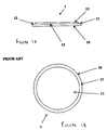
- Figure 1A shows a section through one face of a prior art plate structure
- Figure 1B is a plan view of the plate structure of Figure 1A.
- the plate structure 1 comprises a backing plate 10 which is flat and of uniform thickness.
- the backing plate 10 is generally symmetrical; the plate 10 is shown as circular but other shapes are possible.
- Attached to at least one side of the backing plate 10 is a layer 11 of the active material, for example a polarised electrostrictive material.
- the layer 11 as shown itself takes the form of a circular plate which is flat and of uniform thickness and which is attached to the backing plate 12 by suitable attachment means 13.
- the layer 11 is of such a size that there is an annular area 12 of the backing plate 10 adjacent the outer circumference thereof which is free of active material, although such an area does not necessarily have to be provided.
- the backing plate 10 may be supported on a support structure which can take various forms as shown below.
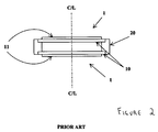
- FIG. 2 it is known to utilise two plate structures of a type illustrated in Figure 1 in a transducer.
- the two structures 1 are separated by an annular support element 20 which is affixed at or near the outer circumference of the backing plate(s) 10 to support and separate the two plate structures.
- the space between the plate structures can be filled with a gas (for example air) or liquid.
- a requirement of a sonar device is that it shall be capable of delivering useful quantities of acoustic power, with a reasonable level of efficiency.
- the achievement of a low fundamental resonance frequency requires, therefore, large mass and/or large compliance.
- the compliance of the device is approximately proportional to ⁇ 1/(thickness) 3 ⁇ of the active material plate and the backing plate; therefore thickening a plate in order to allow the device to operate at greater maximum depth will reduce its effective compliance substantially more than it will increase its effective mass, hence raising the fundamental resonance frequency of the device. There is, therefore, a conflict between the requirements to operate the transducer at a considerable depth and at low fundamental resonance frequency.
- the present invention seeks to provide a transducer incorporating a plate structure which is so constructed that it resolves this conflict and which is capable of operating under extreme conditions, for example at large depths underwater in the order of 200 m.
- the backing plate is of non-uniform thickness.
- the backing plate is supported around its periphery on a support member.
- the backing plate may be thicker at a central region thereof than at an edge region thereof.
- the backing plate may be formed with an outer lip portion of increased thickness relative to an inner region, and in such an arrangement the lip may be bonded to the support structure.
- the active material may be encapsulated in a layer of a polymer material.
- the transducer may have a recess adapted to receive a flexible elongate tensile member, for example a cable; such a recess may be formed in the layer of polymer material.
- the support member may support two backing plates and associated active layers, the second major surfaces of the backing plates and the support structure defining a common region substantially isolated from any external pressure incident on the layers of active material.
- a hydrophone and/or projector may comprise a plurality of transducers as delineated above wherein two said transducers are linked by a cable, and wherein prior to deployment the cable is stored in a recess about the active layer with adjacent transducers being arranged together in close proximity such as to provide a housing for the cable prior to deployment.
- the invention provides a transducer for converting one form of energy into another form of energy comprising a plate structure comprising a backing plate to at least one side of which is affixed an active material which plate structure incorporates a recess adapted to receive a flexible elongate tensile member.
- the transducer of the invention may be operable in use to convert electrical energy into acoustic energy and/or may be operable in use to convert acoustic energy into electrical energy.
- the transducer of the invention may be used underwater and may be included in a sonar system.
- the transducer with which the present invention is concerned operates to convert one form of energy to another form of energy by means of the deformation of a material, referred to as an 'active' material, supported on a backing plate. Because the transducer functions by deformation, the transducer may be referred to in the art as a 'bender'.
- the active material is caused to resonate in such a way that the energy conversion takes place in a controlled and predictable manner.
- the bender transducer if used as a transmitter, it will usually be driven within its resonant bandwidth. This is usually considered to be the resonance frequency ( ⁇ 0 ) itself, and to the -3dB points in terms of the device's maximum electrical conductance (G max ), that is between the frequencies at which the conductance equals G max /2, though other definitions may be applied.
- the device may be used at resonance, or it may be used across a wide frequency band well below ⁇ 0 .
- a bender transducer may, in particular, be used under water either as a transmitter, namely as a "projector”, or as a receiver, namely as a “hydrophone”, or as both.
- the device will be driven with an electrical field alternating at the frequency at which the sound is desired. If it is used as a receiver, it will respond to incoming alternating pressure waves, that is sound, at whatever frequency or frequencies they happen to be, and the device will produce corresponding electrical signals oscillating at the same frequency or frequencies respectively.
- Figures 1A and 1B illustrate diagrammatically a section through a conventional plate structure 1 for use in such a transducer and Figure 2 illustrates the plate structure supported on a support element.
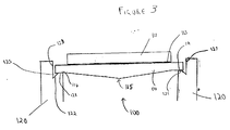
- FIG. 3 a plate structure 100 for a transducer according to the invention.
- the plate structure 100 comprises a steel backing plate 110 of substantially circular shape.
- a layer 111 of active material in the form of a plate is affixed by affixing means 113, for example an adhesive or solder.
- the backing plate 110 instead of being of uniform thickness as in the prior art arrangement has a non-uniform thickness. More particularly, the plate 110 has its greatest thickness at the centre thereof so that the plate comes to a point 115 and the thickness diminishes from the centre towards the outer circumference thereof.
- a region 114 of reduced and substantially uniform thickness At an adjacent outer circumference of the backing plate there is formed a region 114 of reduced and substantially uniform thickness.
- the active material may be of any suitable composition.
- it may be:
- an alternating voltage is applied across each side of each active material plate, usually in the same amplitude to each plate in such a phase relation between one plates and its nearest adjacent plate(s) that the plates flex in opposite directions; for example, the phase relation can be ⁇ radians out of phase between one plate and its nearest adjacent plate(s), the plates being electrically connected.
- incoming acoustic energy will deform the active material plate which generates electrical signals which can be amplified and analysed.
- a polarised electrostrictive material will be affixed to its backing plate after having been raised above a transition temperature, namely its "Curie" temperature, when a polarising electric field will be applied across it. This polarisation is necessary for the material to function in a transducer.
- application of stress induced by for example hydrostatic depth pressure, will depolarise the material rendering it useless for its function in a transducer; the transducer will not thereafter be able to convert electrical energy into mechanical strain or vice versa.
- the plate structure of Figure 3 is modified in that the central region 135 of the backing plate 130 on the side opposite to that to which layer 111 is attached is flattened so that a plateau 135 is formed in that region rather than the point 125 of Figure 3.
- the overall thickness of the plate structure is thereby reduced and this allows a plurality of such plate structures to be packed into a smaller volume than would otherwise be the case; such packing will be described in more detail later.
- the layer of active material is shown as a plate it can be formed on the backing plate by any suitable means
- the layer, namely the plate, of active material may also or alternatively be of variable thickness.
- the plate structure may be 'tuned' to any specific fundamental resonance frequency.
- theoretical tuning of the device may be accomplished by means of finite/boundary element analysis. Such analysis should be followed by construction of a corresponding prototype device.
- a further benefit of the invention is that equalisation of stress and strain distribution in the active material plate will bring about utilisation of a greater volume of the active material plate for the conversion of electrical energy to acoustic energy, and acoustic energy to electrical energy, hence improving the efficiency of the device.
- the plate structure may be supported on a support, for example a spacer which incorporates a passive mass.
- both Figures 3 and 4 show the respective plate structures 110, 130 mounted on a support structure 120.
- this support structure will conveniently be of annular form but other forms are possible.
- the backing plate is secured to the support structure by any suitable means, for example by resin adhesive bonding or by utilising solder.
- the support structure may further support a second composite plate structure opposed to the first; such a composite structure is illustrated in Figure 7.
- the support structure 120 is of generally columnar section but has a portion cut-away at its end adjacent the outer edge region of the backing plate 110. More especially the cut-away portion is formed to provide a planar section 121 which is attached to a planar edge region 114 of the backing plate 110; the cut-away portion further comprises an angled portion 122 and an axially extending portion 123.
- a recess 125 is formed in the support 120 adjacent to the outer edge region of the backing plate. As shown, this recess 125 is of generally triangular cross-section but it is to be understood that other forms are possible.
- the plate structure when the plate structure resonates by moving in a pivoting back-and-forth motion; during such movement, interengaging portions of the edge region of the backing plate 110, 130 and of the support structure form a hinge arrangement.
- the effective compliance of the transducer is increased. Indeed, the dimensions of the recess may be chosen to tune the transducer to the required fundamental resonance frequency.
- Figure 5 shows a modification of the plate structure of Figure 3 or Figure 4 in which the radially outer region of the backing plate 170 of a composite plate structure is formed with a region 180 of increased thickness.
- the region constitutes an axially extending projection whose radially outer surface 181 engages the axially extending portion 123 of the support structure. It provides an increased area for attachment, for example attachment by bonding, to the support structure which is important for preventing detachment of the plate structure from the support under conditions of high electrical drive at low hydrostatic pressure, for example at shallow depths in the order of 1 to 10 m, without increasing the maximum thickness of the composite plate structure.
- the projection is also useful in production of the backing plate since it provides a means by which the plate can be held during lathe-turning operations for example.
- the transducer is immersed in an electrically insulating liquid, such as castor oil, enclosed within an acoustically-transparent container.
- an electrically insulating liquid such as castor oil
- the live parts of the transducer are encapsulated in an acoustically-transparent polymer such as polyurethane; this method can be refined such that the recess for the flexible elongate member may actually be formed within the polymeric encapsulation.
- the recess is illustrated in Figure 6; further details of embodiments of the invention incorporating such a recess are given later.
- transducers utilising the plate structure as described above may be used together; where the transducer is used in a sonar system, the transducers may be deployed under water.
- transducers will conventionally be connected together by a flexible elongate tensile member which, for example, may take the form of an electrically conducting cable.
- the plate structures as delineated above may be modified to provide a storage means for this tensile member when a plurality of transducers for deployment together are stored prior to deployment, for example stacked in a tubular container.
- the outer edge region of the plate structure may be formed with a recess to receive the tensile member and in the case of circular backing plates the recess will preferably be of annular form extending circumferentially of the backing plate.
- the composite plate structure 200 comprises a backing plate 201 whose thickness varies across the plate. Its thickness diminishes from the centre 202 of the plate 201 towards the edge region 203 thereof. At the edge region 203 the plate is formed with a region 208 of increased thickness which is bonded to a support structure 220. Affixed to the surface 204 of the backing plate 201 is plate 210 formed of active material which plate 210 itself may be of variable thickness thereacross. The exposed surfaces of the plate 210 are covered in an acoustically-transparent polymer 230 such as a polyurethane applied, for example by casting with the aid of a mould tool or by dip-coating.
- an acoustically-transparent polymer 230 such as a polyurethane applied, for example by casting with the aid of a mould tool or by dip-coating.
- the coating 230 of polymer also extends over part of the exposed edge region 203 of the backing plate 201 although the upper surface 205 of region 203 need not be coated.
- the coating 230 is formed in such a way that a recess 231 is provided therein.
- the recess 231 is provided adjacent the outer edge region 203 of the backing plate 201 and is of annular form; it is bounded by the polymer coating 230 on three sides and is open at the top whereby to be able to receive a flexible elongate tensile member 240. In effect the tensile member 240 is nested in use in the recess 231.
- the tensile member may be connected to an electrical driving source or body 300 as illustrated in Figure 9.
- Figure 7 shows a section through a transducer 250 with two opposed composite plate structures 260 affixed to a support structure 270.
- the volume 280 defined between the plate structures 260 and the support structure 270 is filled with a suitable substance which could be a liquid, a gas (for example air), or a foamed material.
- a suitable substance which could be a liquid, a gas (for example air), or a foamed material.
- the transducer may be provided with a valve 290 provided in the support structure for ingress/egress of the gas or liquid.
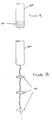
- Figure 9 is a diagrammatic illustration of transducers stacked in a tubular container 300 prior to deployment in an underwater environment.
- the plate structures are arranged immediately adjacent one another with the tensile members arranged in the recesses.
- Figure 10 shows the transducers as deployed, with the elongate tensile members therebetween extended.
Landscapes
- Physics & Mathematics (AREA)
- Engineering & Computer Science (AREA)
- Life Sciences & Earth Sciences (AREA)
- Acoustics & Sound (AREA)
- Remote Sensing (AREA)
- General Physics & Mathematics (AREA)
- Geology (AREA)
- General Life Sciences & Earth Sciences (AREA)
- Environmental & Geological Engineering (AREA)
- Geophysics (AREA)
- Multimedia (AREA)
- Oceanography (AREA)
- Transducers For Ultrasonic Waves (AREA)
- Measuring Fluid Pressure (AREA)
Abstract
Description
- The present invention relates to a pressure tolerant transducer for transforming energy from one form to another, for example for transforming electrical energy into acoustic energy or vice versa.
- Transducers, for example acoustic transducers, are well known in the prior art.
- In a published international patent application no. WO 98/53924, there is disclosed a flexural plate sound transducer comprising a housing having an open central volume, a flexural plate attached around an inner surface of the housing and extending across the central volume, at least one piezoelectric element attached to a surface of the flexural plate. A mechanical hinge is formed near an outer periphery of the flexural plate and extends around the flexural plate. The mechanical hinge is formed such as to cause the flexural plate to move in a substantially piston-like manner when the piezoelectric element is energised. In the published application, the flexural plate and its associated at least one piezoelectric element are of uniform thickness except in the region where the hinge is formed.
- In a published European application EP 0 264 557 A2, there is described a piezo-ceramic sound transducer comprising a metal membrane onto which is bonded in a central region thereof a piezo-ceramic slice. The membrane includes a support ring at a peripheral region thereof, and also a concentric ring-form compliant grove in the membrane between the slice and the support ring. The membrane is of uniform thickness even in the grove.
- In a US patent no. 5 724 315, there is described an omni-directional ultrasonic microprobe hydrophone. The hydrophone comprises two sensing elements where each element is composed of lead zirconate titanate and includes a plurality of columnar voids. In the hydrophone, the elements are bonded to an associated substrate material in the form of a backing plate. The voids are located in the hydrophone between the backing plate and the elements, the voids forming compressible cavities.
- The inventors have appreciated that transducer structures known in the art often experience difficulties coping with relatively elevated environmental pressures applied thereto. Thus, the inventors have developed an alternative transducer exhibiting enhanced resilience to elevated environmental pressure, for example as experienced at a depth in the order of 200 m in aquatic environments.
- The present invention seeks to provide a transducer incorporating a plate structure which is so constructed that it provides a workably low resonant frequency and which is capable of operating under extreme conditions, for example at large depths underwater in the order of 200 m.
- According to a first aspect of the present invention, there is provided a transducer comprising:
- (a) a layer of active material; and
- (b) a backing plate having first and second major surfaces, characterised in that the layer of active material is affixed to the first surface, and the transducer further comprises a region adjacent to the second major surface into which region the backing plate can be deflected, the region being substantially isolated from any external pressure incident on the layer of active material, wherein the backing plate and/or layer of active material is of a non-uniform thickness.
-
- The invention provides the advantage that the transducer is capable of being used in applications where the transducer is exposed to relatively high external pressures.
- One specific usage is where hydrostatic pressure is encountered when the transducer is used underwater. Thus, a transducer of the invention which acts in use to transform electrical energy into acoustic energy may be utilised as a 'projector' in a sonar system where the acoustic energy is broadcast into water. Alternatively, or in addition to, the transducer of the invention may be utilised as a hydrophone in a sonar system where it acts to transform acoustic energy into electrical energy.
- Other applications envisaged for the transducer include diver-to-diver, ship-to-diver and ship-to-ship communications systems, and ships in these contexts should be understood to include 'submarines'.
- The transducer with which the present invention is concerned is of the type which includes a plate structure comprising a backing plate to at least one side, namely a major surface, of which an active material is applied. In the context of the present invention, an active material is defined as:
- (a) a polarised or unpolarised material, such as lead-zirconate titanate, lead titanate, barium titanate, lead metaniobate, lead magnesium niobate/lead titanate (typically either ceramic or single crystalline) or nickel;
- (b) a piezo-electric material, such as crystalline quartz; or
- (c) a magnetostrictive material, such as Terfenol-D.
-
- When the transducer is in use, the active material is deformed by the application of energy in one form and converts that energy into a different form. Thus, in one type of transducer for example, an alternating potential is applied to the two major surfaces of the active material plate via metal electrodes. Such excitation produces an alternating electrical field across the thickness of the active material plate. In response to this field, the plate attempts to expand or contract in the direction of its plane, that is radially in the case of a disc-shaped plate. The backing plate, to which the active material plate is bonded, constrains most of the said strain at or near the bond line. The side of the active material plate remote from the bond line, however, remains reasonably free to expand and contract. The composite plate therefore undergoes periodic flexure. In the case of an underwater projector, this movement is communicated to the surrounding water, and the energy is propagated away as sound.
- In transducers where an active material plate is bonded to each side of a backing plate, the electrical field will be applied to each active material plate in such a phase relation so that the active plates flex in opposite directions, thereby reinforcing each other's action.
- Because of its flexural action, such a transducer is sometimes referred to as a 'bender'.
- The invention provides an improved plate structure which overcomes problems associated with conventional prior art plate structures.
- In this regard Figure 1A shows a section through one face of a prior art plate structure, and Figure 1B is a plan view of the plate structure of Figure 1A.
- The
plate structure 1 comprises abacking plate 10 which is flat and of uniform thickness. Thebacking plate 10 is generally symmetrical; theplate 10 is shown as circular but other shapes are possible. Attached to at least one side of thebacking plate 10 is alayer 11 of the active material, for example a polarised electrostrictive material. Thelayer 11 as shown itself takes the form of a circular plate which is flat and of uniform thickness and which is attached to thebacking plate 12 by suitable attachment means 13. - As shown, the
layer 11 is of such a size that there is anannular area 12 of thebacking plate 10 adjacent the outer circumference thereof which is free of active material, although such an area does not necessarily have to be provided. - It is further known to have layers, for example in plate form, of the active material on both sides of the backing plate; such a configuration is described in a published international application WO 98/53924.
- The
backing plate 10 may be supported on a support structure which can take various forms as shown below. - Further and as illustrated in Figure 2 it is known to utilise two plate structures of a type illustrated in Figure 1 in a transducer. In Figure 2 the two
structures 1 are separated by anannular support element 20 which is affixed at or near the outer circumference of the backing plate(s) 10 to support and separate the two plate structures. The space between the plate structures can be filled with a gas (for example air) or liquid. - Such a prior art structure will, when used underwater, experience hydrostatic pressure from the water, which pressure will increase with depth; such pressure is liable to cause deleterious effects on the structure. Depending on the precise make-up of the structure, there will be a limit to the depth at which the transducer can be used before one or both of the following deleterious consequences ensue:-
- (i) the backing plate and/or the active plate will physically collapse;
- (ii) in the case of polarised active material, the material will suffer depolarisation.
-
- A requirement of a sonar device is that it shall be capable of delivering useful quantities of acoustic power, with a reasonable level of efficiency. In a sonar device incorporating a composite plate structure, the value of the resonance frequency will be determined by the stiffness and masses of the components of the plate structure according to the equation:-
- where ν0 is the fundamental resonance frequency;
- M is the collective effective mass of the relevant components of the structure;
- C is the collective effective compliance of the relevant components of the structure.
-
- It is to be noted that compliance is the inverse of stiffness.
- The achievement of a low fundamental resonance frequency requires, therefore, large mass and/or large compliance. The compliance of the device is approximately proportional to {1/(thickness)3} of the active material plate and the backing plate; therefore thickening a plate in order to allow the device to operate at greater maximum depth will reduce its effective compliance substantially more than it will increase its effective mass, hence raising the fundamental resonance frequency of the device. There is, therefore, a conflict between the requirements to operate the transducer at a considerable depth and at low fundamental resonance frequency.
- The present invention seeks to provide a transducer incorporating a plate structure which is so constructed that it resolves this conflict and which is capable of operating under extreme conditions, for example at large depths underwater in the order of 200 m.
- In the transducer according to the first aspect of the invention, it is preferable that the backing plate is of non-uniform thickness.
- Preferably the backing plate is supported around its periphery on a support member.
- The backing plate may be thicker at a central region thereof than at an edge region thereof.
- It is also envisaged that the backing plate may be formed with an outer lip portion of increased thickness relative to an inner region, and in such an arrangement the lip may be bonded to the support structure.
- The active material may be encapsulated in a layer of a polymer material.
- Also the transducer may have a recess adapted to receive a flexible elongate tensile member, for example a cable; such a recess may be formed in the layer of polymer material.
- The support member may support two backing plates and associated active layers, the second major surfaces of the backing plates and the support structure defining a common region substantially isolated from any external pressure incident on the layers of active material.
- It is envisaged that a hydrophone and/or projector may comprise a plurality of transducers as delineated above wherein two said transducers are linked by a cable, and wherein prior to deployment the cable is stored in a recess about the active layer with adjacent transducers being arranged together in close proximity such as to provide a housing for the cable prior to deployment.
- According to a further aspect, the invention provides a transducer for converting one form of energy into another form of energy comprising a plate structure comprising a backing plate to at least one side of which is affixed an active material which plate structure incorporates a recess adapted to receive a flexible elongate tensile member.
- The transducer of the invention may be operable in use to convert electrical energy into acoustic energy and/or may be operable in use to convert acoustic energy into electrical energy.
- The transducer of the invention may be used underwater and may be included in a sonar system.
- Embodiments of the invention will now be described, by way of example only, with reference to the accompanying drawings wherein:
- Figure 1
- is an illustration of a composite plate structure for use in a transducer and constructed according to the prior art;
- Figure 2
- is an illustration of a prior art arrangement utilising two composite plate structures separated by a support element;
- Figure 3
- is an illustration of a first embodiment of the invention, the embodiment comprising a transducer including a composite plate structure;
- Figure 4
- is an illustration of a second embodiment of the invention, the embodiment comprising a transducer including a composite plate structure;
- Figure 5
- is an illustration of a third embodiment of the invention, the embodiment comprising a transducer including a composite plate structure;
- Figure 6
- is an illustration of a fourth embodiment of the invention, the embodiment comprising a transducer including a composite plate structure;
- Figure 7
- is a sectional view through a composite plate structure of a transducer according to the invention, such structure being associated with a cable whereby it is connectable to other such composite plate structures;
- Figure 8
- is a plan view of the structure of Figure 7;
- Figure 9
- is a schematic illustration of a plurality of transducers comprising composite plate structures packed in a container prior to deployment underwater; and
- Figure 10
- is a schematic illustration of the composite plate structures when deployed from the container of Figure 9.
- As described above, the transducer with which the present invention is concerned operates to convert one form of energy to another form of energy by means of the deformation of a material, referred to as an 'active' material, supported on a backing plate. Because the transducer functions by deformation, the transducer may be referred to in the art as a 'bender'.
- The active material is caused to resonate in such a way that the energy conversion takes place in a controlled and predictable manner. Thus, if the bender transducer is used as a transmitter, it will usually be driven within its resonant bandwidth. This is usually considered to be the resonance frequency (ν0) itself, and to the -3dB points in terms of the device's maximum electrical conductance (Gmax), that is between the frequencies at which the conductance equals Gmax/2, though other definitions may be applied.
- If the device is used as a receiver, it may be used at resonance, or it may be used across a wide frequency band well below ν0.
- A bender transducer may, in particular, be used under water either as a transmitter, namely as a "projector", or as a receiver, namely as a "hydrophone", or as both.
- If used as a transmitter, the device will be driven with an electrical field alternating at the frequency at which the sound is desired. If it is used as a receiver, it will respond to incoming alternating pressure waves, that is sound, at whatever frequency or frequencies they happen to be, and the device will produce corresponding electrical signals oscillating at the same frequency or frequencies respectively.
- Figures 1A and 1B illustrate diagrammatically a section through a
conventional plate structure 1 for use in such a transducer and Figure 2 illustrates the plate structure supported on a support element. - The problems encountered with the prior art transducers incorporating these conventional plate structures have been rehearsed above in detail but involve the deleterious effects caused by the large hydrostatic pressure when the transducer is used at depths.
- In Figure 3 is shown a
plate structure 100 for a transducer according to the invention. Theplate structure 100 comprises asteel backing plate 110 of substantially circular shape. To one side of the backing plate a layer 111 of active material in the form of a plate is affixed by affixing means 113, for example an adhesive or solder. Thebacking plate 110 instead of being of uniform thickness as in the prior art arrangement has a non-uniform thickness. More particularly, theplate 110 has its greatest thickness at the centre thereof so that the plate comes to apoint 115 and the thickness diminishes from the centre towards the outer circumference thereof. At an adjacent outer circumference of the backing plate there is formed aregion 114 of reduced and substantially uniform thickness. - The active material may be of any suitable composition. For example, it may be:
- (a) a polarised or unpolarised electrostrictive material such as lead-zirconate titanate, lead titanate, barium titanate, lead metaniobate, lead magnesium niobate/lead titanate (all either ceramic or single crystalline), or nickel; or
- (b) a piezoelectric material such as crystalline quartz; or
- (c) a magnetostrictive material such as Terfenol D.
-
- In operation of the transducer as a projector with two or four active material plates, an alternating voltage is applied across each side of each active material plate, usually in the same amplitude to each plate in such a phase relation between one plates and its nearest adjacent plate(s) that the plates flex in opposite directions; for example, the phase relation can be π radians out of phase between one plate and its nearest adjacent plate(s), the plates being electrically connected. This results in the application of a periodic bending moment across each composite plate structure. This causes periodic mechanical strain which is communicated to the water in which the transducer is immersed and is transformed to acoustic energy which is radiated away. On the other hand, in operation as a hydrophone, incoming acoustic energy will deform the active material plate which generates electrical signals which can be amplified and analysed.
- A polarised electrostrictive material will be affixed to its backing plate after having been raised above a transition temperature, namely its "Curie" temperature, when a polarising electric field will be applied across it. This polarisation is necessary for the material to function in a transducer. In the prior art arrangements of Figures 1A, 1B, 2 application of stress, induced by for example hydrostatic depth pressure, will depolarise the material rendering it useless for its function in a transducer; the transducer will not thereafter be able to convert electrical energy into mechanical strain or vice versa.
- In the embodiment of Figure 4 the plate structure of Figure 3 is modified in that the
central region 135 of thebacking plate 130 on the side opposite to that to which layer 111 is attached is flattened so that aplateau 135 is formed in that region rather than thepoint 125 of Figure 3. The overall thickness of the plate structure is thereby reduced and this allows a plurality of such plate structures to be packed into a smaller volume than would otherwise be the case; such packing will be described in more detail later. - Although the layer of active material is shown as a plate it can be formed on the backing plate by any suitable means
- The layer, namely the plate, of active material may also or alternatively be of variable thickness.
- By suitable controlled shaping of the thickness of the backing plate and the active layer the plate structure may be 'tuned' to any specific fundamental resonance frequency.
- In this regard the resonance frequency may, in principle, be derived from a relationship
- In the prior art, most of the stress induced in the active material plate by externally-applied hydrostatic pressure, such as by deep immersion in an ocean, will occur at its centre, and little stress will occur towards its perimeter. Profiling the backing plate enables the stress distribution in the active material plate to be equalised. The elimination of regions of stress concentration in the active material helps permit operation at enhanced depths. In particular, the most commonly used active materials are polarised electrostrictive ceramics of lead-zirconate titanate. Externally- imposed depth pressure will cause:-
- (i) loss of polarisation and hence loss of the capability to convert electrical signals to flexural motion, and vice versa; and
- (ii) eventual physical destruction by cracking.
-
- In the prior art, most of the strain induced in an active material plate by an applied alternating electrical field, or by impinging acoustic waves, will occur at its centre, and little strain will occur towards its perimeter, so a relatively small proportion of the volume of the active material plate will be utilised for energy conversion, which will have a deleterious effect upon the efficiency of the device.
- A further benefit of the invention is that equalisation of stress and strain distribution in the active material plate will bring about utilisation of a greater volume of the active material plate for the conversion of electrical energy to acoustic energy, and acoustic energy to electrical energy, hence improving the efficiency of the device.
- The plate structure may be supported on a support, for example a spacer which incorporates a passive mass.
- However, both Figures 3 and 4 show the
respective plate structures support structure 120. In the case of a circular backing plate this support structure will conveniently be of annular form but other forms are possible. The backing plate is secured to the support structure by any suitable means, for example by resin adhesive bonding or by utilising solder. It is to be understood that the support structure may further support a second composite plate structure opposed to the first; such a composite structure is illustrated in Figure 7. - As shown in Figures 3, 4 the
support structure 120 is of generally columnar section but has a portion cut-away at its end adjacent the outer edge region of thebacking plate 110. More especially the cut-away portion is formed to provide aplanar section 121 which is attached to aplanar edge region 114 of thebacking plate 110; the cut-away portion further comprises anangled portion 122 and anaxially extending portion 123. By virtue of the cut-away arecess 125 is formed in thesupport 120 adjacent to the outer edge region of the backing plate. As shown, thisrecess 125 is of generally triangular cross-section but it is to be understood that other forms are possible. - It is to be understood that when the plate structure resonates by moving in a pivoting back-and-forth motion; during such movement, interengaging portions of the edge region of the
backing plate - Figure 5 shows a modification of the plate structure of Figure 3 or Figure 4 in which the radially outer region of the
backing plate 170 of a composite plate structure is formed with aregion 180 of increased thickness. In effect the region constitutes an axially extending projection whose radiallyouter surface 181 engages theaxially extending portion 123 of the support structure. It provides an increased area for attachment, for example attachment by bonding, to the support structure which is important for preventing detachment of the plate structure from the support under conditions of high electrical drive at low hydrostatic pressure, for example at shallow depths in the order of 1 to 10 m, without increasing the maximum thickness of the composite plate structure. The projection is also useful in production of the backing plate since it provides a means by which the plate can be held during lathe-turning operations for example. - It is to be understood that for acoustic energy - electric energy transducers which are to be used underwater those parts of the transducers which are electrically live in use must be protected from electrical contact with the water. In one method of achieving such protection, the transducer is immersed in an electrically insulating liquid, such as castor oil, enclosed within an acoustically-transparent container. In another method, at least the live parts of the transducer are encapsulated in an acoustically-transparent polymer such as polyurethane; this method can be refined such that the recess for the flexible elongate member may actually be formed within the polymeric encapsulation. The recess is illustrated in Figure 6; further details of embodiments of the invention incorporating such a recess are given later.
- It is envisaged that a number of transducers utilising the plate structure as described above may be used together; where the transducer is used in a sonar system, the transducers may be deployed under water. Such transducers will conventionally be connected together by a flexible elongate tensile member which, for example, may take the form of an electrically conducting cable.
- The plate structures as delineated above may be modified to provide a storage means for this tensile member when a plurality of transducers for deployment together are stored prior to deployment, for example stacked in a tubular container.
- More particularly, the outer edge region of the plate structure may be formed with a recess to receive the tensile member and in the case of circular backing plates the recess will preferably be of annular form extending circumferentially of the backing plate.
- Detailed embodiments of arrangements incorporating such recesses are shown in Figures 6, 7 and 8.
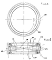
- In Figure 6 the
composite plate structure 200 comprises abacking plate 201 whose thickness varies across the plate. Its thickness diminishes from thecentre 202 of theplate 201 towards theedge region 203 thereof. At theedge region 203 the plate is formed with a region 208 of increased thickness which is bonded to a support structure 220. Affixed to thesurface 204 of thebacking plate 201 isplate 210 formed of active material whichplate 210 itself may be of variable thickness thereacross. The exposed surfaces of theplate 210 are covered in an acoustically-transparent polymer 230 such as a polyurethane applied, for example by casting with the aid of a mould tool or by dip-coating. - The
coating 230 of polymer also extends over part of the exposededge region 203 of thebacking plate 201 although the upper surface 205 ofregion 203 need not be coated. Thecoating 230 is formed in such a way that arecess 231 is provided therein. Therecess 231 is provided adjacent theouter edge region 203 of thebacking plate 201 and is of annular form; it is bounded by thepolymer coating 230 on three sides and is open at the top whereby to be able to receive a flexible elongatetensile member 240. In effect thetensile member 240 is nested in use in therecess 231. The tensile member may be connected to an electrical driving source orbody 300 as illustrated in Figure 9. - Figure 7 shows a section through a
transducer 250 with two opposedcomposite plate structures 260 affixed to asupport structure 270. Thevolume 280 defined between theplate structures 260 and thesupport structure 270 is filled with a suitable substance which could be a liquid, a gas (for example air), or a foamed material. Where the volume is to be filled with a gas or liquid the transducer may be provided with avalve 290 provided in the support structure for ingress/egress of the gas or liquid. - Figure 9 is a diagrammatic illustration of transducers stacked in a
tubular container 300 prior to deployment in an underwater environment. The plate structures are arranged immediately adjacent one another with the tensile members arranged in the recesses. - Figure 10 shows the transducers as deployed, with the elongate tensile members therebetween extended.
Claims (18)
- A pressure tolerant transducer (100) comprising:(a) a layer of active material (111); and(b) a backing plate (110) having first and second major surfaces, characterised in that the layer of active material (111) is affixed to the first surface (113), and the transducer further comprises a region adjacent to the second major surface into which region the backing plate (110) can be deflected, the region (110) being substantially isolated from any external pressure incident on the layer of active material (111), wherein the backing plate (110) and/or layer of active material (111) is of a non-uniform thickness.
- A transducer (100) according to Claim 1 wherein the backing plate (110; 130; 201) is of non-uniform thickness.
- A transducer according to Claim 1 or 2 wherein the backing plate (110) is supported round its periphery (114) on a support member (120).
- A transducer according to any preceding claim wherein the backing plate is thicker at a central region thereof than at an edge region thereof.
- A transducer according to any one of Claims 1 to 3 wherein the backing plate (170) is formed with an outer lip portion (180) of increased thickness relative to an inner region.
- A transducer according to Claim 5 wherein the lip (180) is bonded to the support structure.
- A transducer as claimed in any preceding claim wherein the active material is encapsulated in a layer of a polymer material (260).
- A transducer as claimed in any preceding claim having a recess adapted to receive a flexible elongate tensile member .
- A transducer as claimed in Claim 7 and Claim 8 wherein the recess is formed in the layer of polymer material.
- A transducer as claimed in Claim 8 or 9 wherein the flexible elongate tensile member is a cable.
- A transducer as claimed in any of Claims 7 to 10 in combination with at least one said flexible elongate member and at least one other transducer.
- A transducer as claimed in Claim 3 or any claim dependant thereon wherein the support member (270) supports two backing plates (201) and associated active layers (210), the second major surfaces of the backing plates and the support structure defining a common region (280) substantially isolated from any external pressure incident on the layers of active material (210).
- A hydrophone and/or projector comprising a plurality of transducers as claimed in any preceding claim wherein two said transducers are linked by a cable, and wherein prior to deployment the cable is stored in a recess about the active layer with adjacent transducers being arranged together in close proximity such as to provide a housing for the cable prior to deployment.
- A transducer for converting one form of energy into another form of energy comprising a plate structure comprising a backing plate to at least one side of which is affixed an active material which plate structure incorporates a recess adapted to receive a flexible elongate tensile member.
- A transducer as claimed in any preceding claim operable to convert electrical energy into acoustic energy.
- A transducer as claimed in any preceding claim operable to convert acoustic energy into electrical energy.
- A transducer as claimed in any preceding claim adapted for use underwater.
- A sonar system incorporating a transducer as claimed in any preceding claim.
Applications Claiming Priority (2)
| Application Number | Priority Date | Filing Date | Title |
|---|---|---|---|
| GB9907692 | 1999-04-01 | ||
| GB9907692A GB2348564B (en) | 1999-04-01 | 1999-04-01 | Transducers |
Publications (2)
| Publication Number | Publication Date |
|---|---|
| EP1041537A2 true EP1041537A2 (en) | 2000-10-04 |
| EP1041537A3 EP1041537A3 (en) | 2004-12-01 |
Family
ID=10850938
Family Applications (1)
| Application Number | Title | Priority Date | Filing Date |
|---|---|---|---|
| EP00301527A Withdrawn EP1041537A3 (en) | 1999-04-01 | 2000-02-25 | Pressure tolerant transducer |
Country Status (5)
| Country | Link |
|---|---|
| US (1) | US6404106B1 (en) |
| EP (1) | EP1041537A3 (en) |
| AU (1) | AU764795B2 (en) |
| CA (1) | CA2300765C (en) |
| GB (1) | GB2348564B (en) |
Families Citing this family (7)
| Publication number | Priority date | Publication date | Assignee | Title |
|---|---|---|---|---|
| US6637877B1 (en) | 2002-08-09 | 2003-10-28 | Gentex Corporation | Eyewear for ballistic and light protection |
| US6923537B2 (en) * | 2002-08-09 | 2005-08-02 | Gentex Corporation | Eyewear for ballistic and light protection |
| US7154813B2 (en) * | 2003-07-19 | 2006-12-26 | Qortek, Inc. | Pressure sensitive sensor for real-time reconfigurable sonar applications |
| US7206258B1 (en) | 2005-04-13 | 2007-04-17 | United States Of America As Represented By The Secretary Of The Navy | Dual response acoustical sensor system |
| FR2920535B1 (en) * | 2007-08-30 | 2009-11-27 | Hill Rom Ind Sa | PRESSURE DETECTION AND MEASURING SENSOR INCORPORATING AT LEAST ONE RESISTIVE FORCE DETECTION CELL |
| FR2946427B1 (en) * | 2009-06-05 | 2011-09-30 | Hill Rom Ind Sa | PRESSURE SENSOR COMPRISING A CAPACITIVE CELL AND SUPPORT DEVICE HAVING THE SAME. |
| US10488542B2 (en) | 2014-12-02 | 2019-11-26 | Pgs Geophysical As | Use of external driver to energize a seismic source |
Citations (4)
| Publication number | Priority date | Publication date | Assignee | Title |
|---|---|---|---|---|
| US3360664A (en) | 1964-10-30 | 1967-12-26 | Gen Dynamics Corp | Electromechanical apparatus |
| US3663933A (en) | 1970-07-02 | 1972-05-16 | Us Navy | Protective band for bilaminar transducer with slotted spacer ring |
| US4747192A (en) * | 1983-12-28 | 1988-05-31 | Kabushiki Kaisha Toshiba | Method of manufacturing an ultrasonic transducer |
| US5724315A (en) | 1996-05-29 | 1998-03-03 | The United States Of America As Represented By The Secretary Of The Navy | Omnidirectional ultrasonic microprobe hydrophone |
Family Cites Families (8)
| Publication number | Priority date | Publication date | Assignee | Title |
|---|---|---|---|---|
| US2967956A (en) * | 1955-04-19 | 1961-01-10 | Gulton Ind Inc | Transducer |
| US3206558A (en) * | 1961-09-22 | 1965-09-14 | Erie Technological Prod Inc | Microphone |
| US3988620A (en) * | 1971-11-26 | 1976-10-26 | Aquatronics, Inc. | Transducer having enhanced acceleration cancellation characteristics |
| JPH0834649B2 (en) * | 1986-03-31 | 1996-03-29 | 日本特殊陶業株式会社 | Piezoelectric transducer |
| DE3629093A1 (en) * | 1986-08-27 | 1988-03-10 | Stettner & Co | PIEZOCERAMIC SOUND CONVERTER |
| JPH0632552B2 (en) * | 1989-02-13 | 1994-04-27 | 株式会社海藤製作所 | Composite piezoelectric vibrating element |
| US4999819A (en) * | 1990-04-18 | 1991-03-12 | The Pennsylvania Research Corporation | Transformed stress direction acoustic transducer |
| US5956293A (en) * | 1997-05-27 | 1999-09-21 | Raytheon Company | Flexural plate sound transducer having low resonant frequency |
-
1999
- 1999-04-01 GB GB9907692A patent/GB2348564B/en not_active Expired - Fee Related
-
2000
- 2000-02-25 EP EP00301527A patent/EP1041537A3/en not_active Withdrawn
- 2000-03-16 CA CA002300765A patent/CA2300765C/en not_active Expired - Fee Related
- 2000-03-30 AU AU24210/00A patent/AU764795B2/en not_active Ceased
- 2000-04-03 US US09/541,932 patent/US6404106B1/en not_active Expired - Lifetime
Patent Citations (4)
| Publication number | Priority date | Publication date | Assignee | Title |
|---|---|---|---|---|
| US3360664A (en) | 1964-10-30 | 1967-12-26 | Gen Dynamics Corp | Electromechanical apparatus |
| US3663933A (en) | 1970-07-02 | 1972-05-16 | Us Navy | Protective band for bilaminar transducer with slotted spacer ring |
| US4747192A (en) * | 1983-12-28 | 1988-05-31 | Kabushiki Kaisha Toshiba | Method of manufacturing an ultrasonic transducer |
| US5724315A (en) | 1996-05-29 | 1998-03-03 | The United States Of America As Represented By The Secretary Of The Navy | Omnidirectional ultrasonic microprobe hydrophone |
Also Published As
| Publication number | Publication date |
|---|---|
| EP1041537A3 (en) | 2004-12-01 |
| US6404106B1 (en) | 2002-06-11 |
| GB2348564B (en) | 2003-06-18 |
| AU2421000A (en) | 2000-10-05 |
| CA2300765C (en) | 2009-12-15 |
| GB2348564A (en) | 2000-10-04 |
| GB9907692D0 (en) | 1999-05-26 |
| AU764795B2 (en) | 2003-08-28 |
| CA2300765A1 (en) | 2000-10-01 |
Similar Documents
| Publication | Publication Date | Title |
|---|---|---|
| EP2844400B1 (en) | Ultra wide bandwidth transducer with dual electrode | |
| US5196755A (en) | Piezoelectric panel speaker | |
| US6232702B1 (en) | Flextensional metal-ceramic composite transducer | |
| US3370187A (en) | Electromechanical apparatus | |
| US4072871A (en) | Electroacoustic transducer | |
| EP0258948B1 (en) | Flexural dish resonant cavity transducer | |
| US6614143B2 (en) | Class V flextensional transducer with directional beam patterns | |
| US7453772B2 (en) | Flexural cylinder projector | |
| US6404106B1 (en) | Pressure tolerant transducer | |
| US20080212807A1 (en) | Micromachined Acoustic Transducers | |
| US3460061A (en) | Electroacoustic transducer with improved shock resistance | |
| Newnham et al. | Cymbal transducers: a review | |
| JP2008244895A (en) | Bending-type wave transmitter/receiver | |
| JP2023549917A (en) | Ultrasonic transducer array device | |
| JP2001333487A (en) | Bent type wave transmitter-receiver | |
| Sadeghpour et al. | Coupled piezoelectric bulk-micromachined ultrasound trasndcuer (cpb-mut): An ultrasound transducer with enhanced pressure response in liquid and dense medium | |
| EP3532210B1 (en) | Acoustic transducer | |
| JP6514079B2 (en) | Sound generator | |
| JP5309941B2 (en) | Acoustic transducer | |
| JPH0311898A (en) | Wave transmitter-receiver | |
| JP7253094B1 (en) | piezoelectric speaker | |
| JPS6143098A (en) | Low frequency underwater ultrasonic transmitter | |
| JP2024070453A (en) | Transmitting/receiving device and transmitting/receiving method | |
| Newnham et al. | Underwater flat-panel transducer arrays | |
| JPH0445348Y2 (en) |
Legal Events
| Date | Code | Title | Description |
|---|---|---|---|
| PUAI | Public reference made under article 153(3) epc to a published international application that has entered the european phase |
Free format text: ORIGINAL CODE: 0009012 |
|
| AK | Designated contracting states |
Kind code of ref document: A2 Designated state(s): AT BE CH CY DE DK ES FI FR GB GR IE IT LI LU MC NL PT SE |
|
| AX | Request for extension of the european patent |
Free format text: AL;LT;LV;MK;RO;SI |
|
| RAP1 | Party data changed (applicant data changed or rights of an application transferred) |
Owner name: THALES UNDERWATER SYSTEMS LIMITED |
|
| PUAL | Search report despatched |
Free format text: ORIGINAL CODE: 0009013 |
|
| AK | Designated contracting states |
Kind code of ref document: A3 Designated state(s): AT BE CH CY DE DK ES FI FR GB GR IE IT LI LU MC NL PT SE |
|
| AX | Request for extension of the european patent |
Extension state: AL LT LV MK RO SI |
|
| 17P | Request for examination filed |
Effective date: 20050525 |
|
| AKX | Designation fees paid |
Designated state(s): AT BE CH CY DE DK ES FI FR GB GR IE IT LI LU MC NL PT SE |
|
| 17Q | First examination report despatched |
Effective date: 20080520 |
|
| RAP1 | Party data changed (applicant data changed or rights of an application transferred) |
Owner name: THALES HOLDINGS UK PLC |
|
| RAP1 | Party data changed (applicant data changed or rights of an application transferred) |
Owner name: THALES HOLDINGS UK PLC |
|
| STAA | Information on the status of an ep patent application or granted ep patent |
Free format text: STATUS: THE APPLICATION IS DEEMED TO BE WITHDRAWN |
|
| 18D | Application deemed to be withdrawn |
Effective date: 20180706 |