EP1040994B1 - Fahrradkupplungseinrichtung für einen Seilzug - Google Patents
Fahrradkupplungseinrichtung für einen Seilzug Download PDFInfo
- Publication number
- EP1040994B1 EP1040994B1 EP20000105740 EP00105740A EP1040994B1 EP 1040994 B1 EP1040994 B1 EP 1040994B1 EP 20000105740 EP20000105740 EP 20000105740 EP 00105740 A EP00105740 A EP 00105740A EP 1040994 B1 EP1040994 B1 EP 1040994B1
- Authority
- EP
- European Patent Office
- Prior art keywords
- wall
- cable
- detenting
- forming
- recess
- Prior art date
- Legal status (The legal status is an assumption and is not a legal conclusion. Google has not performed a legal analysis and makes no representation as to the accuracy of the status listed.)
- Expired - Lifetime
Links
- 230000008878 coupling Effects 0.000 title claims description 13
- 238000010168 coupling process Methods 0.000 title claims description 13
- 238000005859 coupling reaction Methods 0.000 title claims description 13
- 230000007246 mechanism Effects 0.000 claims description 10
- 230000004044 response Effects 0.000 claims description 6
- 230000005540 biological transmission Effects 0.000 claims description 3
- 230000003014 reinforcing effect Effects 0.000 description 3
- 230000007480 spreading Effects 0.000 description 2
- 238000004804 winding Methods 0.000 description 2
- 230000000712 assembly Effects 0.000 description 1
- 238000000429 assembly Methods 0.000 description 1
- 230000000694 effects Effects 0.000 description 1
- 239000000463 material Substances 0.000 description 1
- 230000004048 modification Effects 0.000 description 1
- 238000012986 modification Methods 0.000 description 1
- 239000011347 resin Substances 0.000 description 1
- 229920005989 resin Polymers 0.000 description 1
- 230000000284 resting effect Effects 0.000 description 1
- 239000000725 suspension Substances 0.000 description 1
Images


Classifications
-
- B—PERFORMING OPERATIONS; TRANSPORTING
- B62—LAND VEHICLES FOR TRAVELLING OTHERWISE THAN ON RAILS
- B62M—RIDER PROPULSION OF WHEELED VEHICLES OR SLEDGES; POWERED PROPULSION OF SLEDGES OR SINGLE-TRACK CYCLES; TRANSMISSIONS SPECIALLY ADAPTED FOR SUCH VEHICLES
- B62M25/00—Actuators for gearing speed-change mechanisms specially adapted for cycles
- B62M25/02—Actuators for gearing speed-change mechanisms specially adapted for cycles with mechanical transmitting systems, e.g. cables, levers
Definitions
- the present invention is directed to bicycle control devices and, more particularly, to n bicycle device which includes a break-away attachment for a connecting cable.
- an indicator unit for engaging a first control cable connected to a first bicycle shift control device and for engaging a second control cable connected to a second bicycle shift control device.
- the indicator unit includes a housing; a handlebar attachment member for attaching the housing to a handlebar; a first intermediate member; a first coupling member coupled to the first intermediate member for coupling the first intermediate member for movement with the first control cable; and a separate first indicating member viewable from outside the housing, wherein the first indicating member engages the first intermediate member so that movement of the first intermediate member causes movement of the first indicating member.
- the indicator unit also includes a second intermediate member; a second coupling member coupled to the second intermediate member for coupling the second intermediate member for movement with the second control cable; and a separate second indicating member viewable from outside the housing, wherein the second indicating member engages the second intermediate member so that movement of the second intermediate member along the guide surface causes movement of the second indicating member.
- Each first and second intermediate member includes a cable terminating structure with a cable slot formed therein for retaining a cable end protuberance attached to the end of its associated control cable.
- pulling the control cable causes a pulling force on the cable terminating structure which, in turn, moves the intermediate member.
- a decrease in the size of the intermediate member involves a corresponding decrease in size of the cable terminating structure. This, in turn, causes a decrease in strength of the cable terminating structure.
- a strong pulling force is applied to the control cable, there is a risk that the cable terminating structure will become damaged.
- it is desirable to make a cable terminating structure which can accommodate strong control cable pulling forces. This is true not only for a bicycle indicating unit described above, but also for other bicycle devices such as shift levers, suspension adjusting levers, and so on.
- an apparatus for coupling a pulling cable of a bicycle control device, the cable having a cable end protuberance attached thereto comprises a member having a cable terminating structure, wherein the cable terminating structure includes a first wall forming a first detenting structure and a second wall being spaced apart from the first wall, thereby forming a receiving space for a cable end protuberance between the first detenting structure and the second wall and a resilient portion included in at least one of the first wall and the second wall for deflecting so as to release the cable end protuberance from the cable terminating structure, wherein the resilient portion is adapted to be deflected in response to a pulling force applied to the cable terminating structure, and comprises a deflecting adjusting mechanism for adjusting an amount of force required to deflect the resilient portion.
- the first wall includes a first detenting recess in the form of a first detenting opening extending entirely through the first wall for forming the first detenting structure. Additionally, the first wall includes a slot extending from the first detenting opening through a side edge of the first wall. This facilitates assembly of the control cable to the cable terminating structure because, if the first detenting opening is made large enough, the cable end protuberance and control cable can be passed through the first detenting opening and slot, respectively, until the control cable is sandwiched between the first and second walls.
- the second wall may include a second detenting recess for forming the second detenting structure. If the cable end protuberance has a spherical shape, then the cable end protuberance may be disconnected easily from the cable terminating structure in the event of excessive pulling forces applied to the control cable.
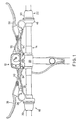
- Figure 1 is a top view of a particular embodiment of an indicator unit 10 according to the present invention, wherein indicator unit 10 is attached to a bicycle handlebar 14, to a front shift control device 18 and to a rear shift control device 22.
- Front shift control device 18 and rear shift control device 22 may be constructed according to the teachings of allowed U.S. Patent Application Number 08/854,520, U.S. Patent Number 3,633,437, both incorporated herein by reference, or any other type of shift control device that can be modified to accommodate cables used to control indicator unit 10 as described below.
- front shift control device 18 includes a shift control housing 26 and an annular rotatable member 30 rotatably mounted to shift control housing 26.
- Rotatable member 30 operates a pulley (not shown) through an indexing mechanism (not shown) contained within shift control housing 26 to control the operation of a Bowden-type derailleur cable 34 in a well known manner.
- the pulley used to control derailleur cable 34 may have an additional winding surface to accommodate a Bowden-type front indicator cable 35.
- a brake lever 36 is rotatably mounted to shift control housing 26 for controlling a front brake apparatus (not shown) through a Bowden-type brake cable 40.
- rear shift control device 22 includes a shift control housing 46 and an annular rotatable member 50 rotatably mounted to shift control housing 46.
- Rotatable member 50 operates a pulley (not shown) through an indexing mechanism (not shown) contained within shift control housing 46 to control the operation of a Bowden-type derailleur cable 54 in a well known manner.
- the pulley used to control derailleur cable 54 may have an additional winding surface to accommodate a Bowden-type rear indicator cable 55.
- a brake lever 56 is rotatably mounted to shift control housing 46 for controlling a front brake apparatus (not shown) through a Bowden-type brake cable 60.
- indicator unit 10 includes an indicator housing 70, a first handlebar attachment member 74 movably coupled to housing 70 through a first splined connection 78, and a second handlebar attachment member 82 movably coupled to indicator housing 70 through a second splined connection 86.
- First handlebar attachment member 74 normally is oriented generally parallel to second handlebar attachment member 82, and they are spaced apart from each other so that they may be attached to handlebar 14 on opposite sides of a centrally disposed handlebar stem 89.
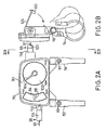
- first and second handlebar attachment members 74 and 82 are formed as U-shaped members as shown in Figure 2(B) (only first handlebar attachment member 74 is shown). First and second handlebar attachment members 74 and 82 are secured to handlebar 14 through nut and bolt assemblies 91 and 93, respectively, in a well known manner.
- a top cover surface 90 of indicator housing 70 includes a transparent window 94 for viewing a front gear indicating member 98 therethrough and a transparent cover 100 for viewing a rear gear indicating member 104 therethrough.
- a front cable stop 110 is disposed on the left side of indicator housing 70 for terminating an outer casing 114 of front indicator cable 35
- a rear cable stop 118 is disposed on the right side of indicator housing 70 for terminating an outer casing 122 of rear indicator cable 55.
- a rear cover 126 ( Figure 2(B)) is pivotably coupled to the rear of indicator housing 70 so that the rear of indicator housing 70 may be accessed for attachment of the inner wires 95 and 97 of front and rear indicator cables 35 and 55, respectively to the components inside indicator housing 70.
- a latch 130 is disposed on the lower portion of rear cover 126 for securing the lower portion of rear cover 126 to indicator housing 70.
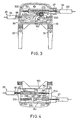
- Figure 3 is a top view of the interior of indicator unit 10
- Figure 4 is a bottom view of the interior of indicator unit 10 (without first and second handlebar attachment members 74 and 82).
- inner wire 95 of front indicator cable 35 is coupled to an intermediate member in the form of a camming member150
- inner wire 97 of rear indicator cable 55 is coupled to an intermediate member in the form of a gearing member 154.
- camming member 150 is a generally rectangular shaped member with a generally flat top surface 160 and a generally flat bottom surface 164.
- a camming wall 168 is disposed on top surface 160.
- Camming wall 168 forms a camming surface 170 including a first inclined surface 172, a first horizontal surface 176, a second inclined surface 180, and a second horizontal surface 184.
- camming surface 170 cooperates with front indicating member 98 to move front indicating member 98 to various locations relative to indicator housing 70.
- Camming member 150 includes a cable terminating structure in the form of a cable terminating projection 190 extending from bottom surface 164 for retaining a cable end protuberance 192 formed on the end of inner wire 95.
- cable terminating projection 190 functions as a coupling member for coupling inner wire 95 to camming member 150.
- Cable terminating projection 190 slides within a straight recessed guide surface or track 193 formed in indicator housing 70 so that camming member 150 moves in a straight line in response to movement of inner wire 95.
- Camming member 150 also includes a spring retaining post 196 extending from bottom surface 164 for retaining one end of a coil spring 200. The other end of coil spring 200 is attached to a spring retaining post 204 extending from the surface of indicator housing 70.
- coil spring 200 functions as a biasing mechanism for biasing camming member 150 to the right in Figures 3 and 4.
- the separate front indicating member 98 includes a support portion 210 rotatably mounted around a pivot shaft 214 extending from indicator housing 70, a generally straight main body portion 218 extending from support portion 210, a cam follower portion 222 projecting at an incline from main body portion 218, a viewing needle support portion 226 arcuately extending approximately perpendicular from the end of main body portion 218, and a generally straight front viewing needle 230 extending from viewing needle support portion 226.
- a spring 234 has one end abutting a spring retaining post 242 extending from indicator case 70 and another end abutting against main body portion 218.
- spring 234 functions as a biasing mechanism for biasing cam follower portion 222 in the direction of arrow A towards camming surface 170 on camming member 150.
- Front viewing needle 230 is in a low speed viewable position 231 relative to indicator housing 70 in this position as shown in Figure 8.
- rotating rotatable member 30 of front shift control device 18 causes the pulley inside housing 26 to pull inner wire 95.
- This causes camming member 150 to move to the left as shown by arrow B in Figures 7 and 8.
- cam follower portion 222 slides along first inclined surface 172 and front gear indicating member 98 rotates around the axis defined by pivot shaft 214 until cam follower portion 222 rests on first horizontal surface 176.
- Front viewing needle 230 is in an intermediate speed viewable position 233 relative to indicator housing 70 in this position. Further rotating of rotatable member 30 and pulling of inner wire 95 causes cam follower portion 222 to slide along second inclined surface 180 until cam follower portion 222 rests on second horizontal surface 184.
- Front viewing needle 230 is in a top or high speed viewable position 235 relative to indicator housing 70 in this position.
- Rotating rotatable member 30 in the opposite direction likewise causes camming member 150 and front gear indicating member 98 to move in the opposite direction with the aid of biasing springs 200 and 234. Since front indicating member 98 moves to different viewable positions relative to indicator housing 70, the rider can sense the currently selected speed stage without having to read numbers.
- gearing member 154 is a generally rectangular shaped member with a generally flat top surface 260 and a generally flat bottom surface 264.
- a gearing wall 268 having a plurality of gearing teeth 270 disposed in a generally straight line extends from top surface 260 as an integral portion of top surface 260.
- the separate rear gear indicating member 104 has the form of a rear gear viewing needle 269 having a gear portion 271 that is rotatably mounted to indicator housing 70 through a pivot shaft 272.
- Gear portion 271 meshes with gearing teeth 270 so that rear gear indicating member 104 rotates around the axis defined by pivot shaft 272 in response to movement of gearing member 154. This, in turn, causes rear gear viewing needle 269 to move to different viewable positions along indicator housing 70.
- Gearing member 154 includes a cable terminating structure in the form of a cable terminating projection 290 extending from bottom surface 264 for retaining a cable end protuberance 292 formed on the end of inner wire 97.
- cable terminating projection 290 functions as a coupling member for coupling inner wire 97 to gearing member 154.
- Cable terminating projection 290 slides within a straight recessed guide surface or track 293 formed in indicator housing 70 so that gearing member 154 moves in a straight line in response to movement of inner wire 97.
- Gearing member 154 also includes a spring retaining post 296 extending from bottom surface 264 for retaining one end of a coil spring 300. The other end of coil spring 300 is attached to a spring retaining post 304 extending from the surface of indicator housing 70.
- coil spring 300 functions as a biasing mechanism for biasing gearing member 154 to the left in Figures 3 and 4.
- rotating rotatable member 50 of rear shift control device 22 causes the pulley inside housing 46 to pull inner wire 97.
- gearing member 154 moves to the right as shown by arrow C in Figure 8.
- rear gear viewing needle 269 moves from a lower speed position 310 toward a higher speed position 314 relative to indicator housing 70 as shown by arrow D.
- Rotating rotatable member 50 in the opposite direction causes gearing member 154 and rear gear indicating needle 269 to move in the opposite direction with the aid of biasing spring 300.
- the number of discrete positions assumed by rear gear viewing needle 269 depends on the number of speeds accommodated by rear shift control device 22.
- front gear indicating member 98 since rear gear indicating member 104 moves to different viewable positions relative to indicator housing 70, the rider can sense the currently selected speed stage without having to read numbers.
- Figure 9 is an oblique view of gearing member 154 showing the detailed structure of cable terminating projection 290 that extends generally perpendicularly from bottom surface 264.
- Figure 10 is a view taken along line X-X in Figure 9;
- Figure 11 is a view taken along line XI-XI in Figure 10, and
- Figure 12 is a view taken along line XII-XII in Figure 11.
- Cable terminating projection 190 of camming member 150 is constructed the same way. More specifically, cable terminating projection 290 includes a first wall 400, a second wall 404 spaced apart from first wall 400, and a bridging wall 408 extending across a rear end 412 of first wall 400 and a rear end 416 of second wall 404.
- First wall 400 includes a first detenting structure in the form of a first detenting opening 420 extending entirely through first wall 400 for receiving the spherically-shaped cable end protuberance 292 attached to inner wire 97.
- second wall 404 includes a second detenting structure in the form of a second detenting opening 428 extending entirely through second wall 404 for receiving the spherically-shaped cable end protuberance 292.
- At least one of first wall 400 and second wall 404 includes a resilient portion for deflecting so as to release the cable end protuberance 292 from the cable terminating projection 290 and wherein the resilient portion is adapted to be deflected in response to a pulling force applied to the cable terminating projection 290, and comprises a deflecting adjusting mechanism for adjusting an amount of force required to deflect the resilient portion.
- the resilient portion can comprise the material forming cable terminating projection 290, such as an elastic resin or a plate spring, or by the structure of first wall 400 and/or second wall 404.
- first wall 400 is affixed to bottom surface 264 only along part of its entire length.
- Rear end 412 of first wall 400, bridging wall 408, and second wall 404 are not connected to bottom surface 264. Instead, there is a space 429 between these structures and bottom surface 264. As a result, second wall 404 functions as a deflectable plate spring in a manner described below. Of course, in other embodiments the space 429 can be omitted, and the resiliency may be obtained in many other ways
- first wall 400 includes a slot 432 extending from first detenting opening 420 through a side edge 434 of the first wall 400. These structures facilitate assembly with the inner wire 97 in a manner discussed below. Front end 450 of first wall 400 and a front end 454 of second wall 404 define a space 458 therebetween for receiving inner wire 97 therethrough in a manner shown in Figure 14. To add some strength to cable terminating projection 290, first wall 400 includes a reinforcing rib 440, and second wall 404 includes a reinforcing rib 444. Reinforcing ribs 440 and 444 also help maintain the position of cable end protuberance 292 at first detenting opening 420 and second detenting opening 428.
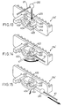
- Figures 13-15 are oblique views showing the assembly and detenting operation of the gearing member 154 shown in Figure 9.
- cable end protuberance 292 and inner wire 97 are passed through first detenting opening 420 and slot 432, respectively, until cable end protuberance 292 is supported in second detenting opening 428.
- inner wire 97 is rotated counterclockwise approximately 90° so that inner wire 97 is sandwiched in space 458 between front end 450 and front end 454.
- cable end protuberance 292 may be resting in both first detenting opening 420 and second detenting opening 428, but that is not necessary.
- cable end protuberance 292 it is also possible for cable end protuberance 292 to rest in second detenting opening 428 alone, with forward movement of cable end protuberance 292 being inhibited by front ends 450 and 454.
- second wall 404 which functions as a plate spring in this embodiment, causes second wall 404 to deflect downward as shown by the arrow in Figure 15 as a result of the forward force exerted by cable end protuberance 292
- cable end protuberance 292 is allowed to exit cable terminating projection 290 without damaging cable terminating projection 290.
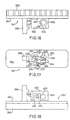
- Figures 16-18 are views corresponding to Figures 10-12, respectively, of another embodiment of a gearing member 154' according to the present invention, wherein identical components are numbered the same as in Figures 10-12.
- a deflection adjusting wall 470 extends generally perpendicularly from bottom surface 264 for supporting a threaded deflection adjusting screw 474 in a threaded opening 475.
- An end 478 of adjusting screw contacts a side 480 of second wall 404. The force required to deflect second wall 404 may be adjusted by adjusting the position of deflection adjusting screw 474.
- the detenting structures in cable terminating projection 290 were shown as openings extending completely through first wall 400 and second wall 404, the detenting structure(s) may be formed as a dimple on first wall 400 and/or second wall 404.
- Detenting opening 420 need not be larger than detenting opening 428.
- Slot 432 may be omitted, whereupon and cable end protuberance 292 may be placed in the detenting structure(s) by manually spreading first wall 400 and second wall 404.
- Cable end protuberance 292 need not be spherical and may be any structure and shape that allows spreading of first wall 400 and second wall 404 without binding.
- the present invention is not limited to a bicycle indicating device, and it has application in any device wherein a member is provided for receiving a pulling force of a control cable.
- the scope of the invention should not be limited by the specific structures disclosed or the apparent initial focus on a particular structure or feature.
Landscapes
- Engineering & Computer Science (AREA)
- Chemical & Material Sciences (AREA)
- Combustion & Propulsion (AREA)
- Transportation (AREA)
- Mechanical Engineering (AREA)
- Flexible Shafts (AREA)
- Steering Devices For Bicycles And Motorcycles (AREA)
Claims (17)
- Vorrichtung zur Kopplung eines Zugkabels (97) einer Fahrradsteuervorrichtung, wobei das Kabel (97) eine an diesem befestigte Kabelendausstülpung (192, 292) aufweist, beinhaltend:dadurch gekennzeichnet, dass der federnde Abschnitt ausgebildet ist, reagierend auf eine auf die Kabelanschlussstruktur (190, 290) ausgeübte Zugkraft durchgebogen zu werden und einen Durchbiegungseinstellmechanismus aufweist, um die Größe der Kraft einzustellen, die zum Durchbiegen des federnden Abschnittes erforderlich ist.ein Element (154, 154') mit einer Kabelanschlussstruktur (190, 290), wobei die Kabelanschlussstruktur beinhaltet:eine erste Wand (400), welche eine erste Raststruktur bildet;eine zweite Wand (404), welche mit Abstand zur ersten Wand angeordnet ist, wodurch ein Aufnahmeraum für eine Kabelendausstülpung (192, 292) zwischen der ersten Raststruktur (420) und der zweiten Wand (404) gebildet wird;einen federnden Abschnitt, der in der ersten Wand und/oder der zweiten Wand enthalten ist, um sich zur Freigabe der Kabelendausstülpung (192, 292) aus der Kabelanschlussstruktur (190, 290) durchzubiegen;
- Vorrichtung nach Anspruch 1, bei welcher die Kabelanschlussstruktur (190, 290) einen Kabelanschlussvorsprung aufweist, der sich von einer Oberfläche des Elementes aus erstreckt.
- Vorrichtung nach Anspruch 1 oder 2, bei welcher die Kabelanschlussstruktur (290) eine Verbindungswand (408) beinhaltet, welche die erste Wand (400) und die zweite Wand (404) verbindet.
- Vorrichtung nach einem der vorhergehenden Ansprüche, bei welcher die Verbindungswand (408) sich über ein hinteres Ende (412) der ersten Wand (400) und ein hinteres Ende (416) der zweiten Wand (404) erstreckt.
- Vorrichtung nach einem der vorhergehenden Ansprüche, bei welcher ein vorderes Ende (450) der ersten Wand (400) und ein vorderes Ende (454) der zweiten Wand (404) einen Zwischenraum (458) zwischen sich begrenzen, welcher zur Aufnahme des Steuerkabels dient.
- Vorrichtung nach einem der vorhergehenden Ansprüche, bei welcher die erste Wand (400) eine erste Rastausnehmung zur Ausbildung der ersten Raststruktur beinhaltet.
- Vorrichtung nach Anspruch 6, bei welcher die erste Wand (400) eine erste Rastöffnung (420) beinhaltet, die sich vollständig durch die erste Wand (400) hindurch erstreckt, um die erste Rastausnehmung zu bilden.
- Vorrichtung nach Anspruch 6 oder 7, bei welcher die erste Wand (400) einen Schlitz (432) beinhaltet, der sich von der ersten Rastöffnung (420) durch eine Seitenkante (434) der ersten Wand (400) hindurch erstreckt.
- Vorrichtung nach Anspruch 6, bei welcher die zweite Wand (404) eine zweite Rastausnehmung zur Ausbildung einer zweiten Raststruktur beinhaltet.
- Vorrichtung nach Anspruch 9, bei welcher die erste Wand (400) eine erste Rastöffnung (420) beinhaltet, welche sich vollständig durch die erste Wand hindurch erstreckt, um die erste Rastausnehmung zu bilden, und wobei die zweite Wand (404) eine zweite Rastöffnung (428) beinhaltet, welche sich vollständig durch die zweite Wand (404) hindurch erstreckt, um die zweite Rastausnehmung zu bilden.
- Vorrichtung nach einem der vorhergehenden Ansprüche, bei welcher sich die erste Wand (400) und/oder die zweite Wand ausgehend von einer Oberfläche des Elementes erstreckt, und wobei die erste Wand und/oder die zweite Wand (404) einen Zwischenraum zwischen der Oberfläche (264) des Elementes und der ersten Wand und/oder der zweiten Wand begrenzen.
- Vorrichtung nach Anspruch 11, bei welcher sich die erste Wand von der Oberfläche (264) des Elementes erstreckt, wobei die zweite Wand mit der ersten Wand über eine Verbindungswand (408) verbunden ist und die gesamte zweite Wand einen Zwischenraum (429) zwischen der Oberfläche (264) des Elementes und der zweiten Wand (404) bildet.
- Vorrichtung nach Anspruch 12, bei welcher der Durchbiegungseinstellmechanismus eine Schraube (474) beinhaltet, deren Ende mit dem federnden Abschnitt in Kontakt steht.
- Vorrichtung nach Anspruch 12 oder 13, bei welcher der Durchbiegungseinstellmechanismus weiter eine Durchbiegungseinstellwand (470) beinhaltet, die sich von einer Oberfläche (264) des Elementes aus erstreckt, und wobei sich die Schraube (474) durch die Durchbiegungseinstellwand (470) hindurch erstreckt.
- Kraftübertragungsvorrichtung, welche ein Steuerkabel (97) mit einer Kabelendausstülpung (292) und eine Vorrichtung nach einem der vorhergehenden Ansprüche beinhaltet, wobei das Element ein Kabelkupplungselement (154, 154') ist.
- Vorrichtung nach Anspruch 15, bei welcher die erste Wand (400) eine erste Rastausnehmung (420) zur Ausbildung der ersten Raststruktur beinhaltet und die Kabelendausstülpung (292) in der ersten Rastausnehmung (420) angeordnet ist.
- Vorrichtung nach Anspruch 16, bei welcher die Kabelendausstülpung (292) kugelförmig ist.
Applications Claiming Priority (2)
| Application Number | Priority Date | Filing Date | Title |
|---|---|---|---|
| US09/280,180 US6763740B1 (en) | 1999-01-27 | 1999-03-29 | Bicycle device with a break-away attachment for a connecting cable |
| US280180 | 1999-03-29 |
Publications (3)
| Publication Number | Publication Date |
|---|---|
| EP1040994A2 EP1040994A2 (de) | 2000-10-04 |
| EP1040994A3 EP1040994A3 (de) | 2003-05-07 |
| EP1040994B1 true EP1040994B1 (de) | 2005-01-19 |
Family
ID=23072020
Family Applications (1)
| Application Number | Title | Priority Date | Filing Date |
|---|---|---|---|
| EP20000105740 Expired - Lifetime EP1040994B1 (de) | 1999-03-29 | 2000-03-17 | Fahrradkupplungseinrichtung für einen Seilzug |
Country Status (5)
| Country | Link |
|---|---|
| EP (1) | EP1040994B1 (de) |
| JP (1) | JP2000297812A (de) |
| CN (1) | CN1165449C (de) |
| DE (1) | DE60017485T2 (de) |
| TW (1) | TW446663B (de) |
Families Citing this family (1)
| Publication number | Priority date | Publication date | Assignee | Title |
|---|---|---|---|---|
| DE102007008054A1 (de) * | 2007-02-15 | 2008-08-21 | Sram Deutschland Gmbh | Schalter für ein Fahrrad |
Family Cites Families (7)
| Publication number | Priority date | Publication date | Assignee | Title |
|---|---|---|---|---|
| DE1106830B (de) * | 1960-02-04 | 1961-05-18 | Stocko Metallwarenfabriken Hug | Flachstecker fuer elektrische Leitungen |
| US3633437A (en) | 1969-07-31 | 1972-01-11 | Takuo Ishida | Hand control device for speed change gear mechanism of a bicycle |
| DE8225387U1 (de) * | 1982-09-09 | 1984-09-06 | Fichtel & Sachs Ag, 8720 Schweinfurt | Verbindungseinrichtung fuer einen betaetigungsschaltzug |
| DE3429327C2 (de) * | 1984-01-20 | 1986-11-27 | Freko Verbindungselemente + Technik GmbH, 5990 Altena | Einrichtung zur Verbindung eines Schaltzugs mit einer Mehrgangschaltung für Fahrräder oder dergleichen |
| ES2014639A6 (es) * | 1989-06-05 | 1990-07-16 | Pujol & Tarago | Dispositivo de enganche para cables metalicos. |
| US5528711A (en) * | 1989-11-24 | 1996-06-18 | Nippon Telegraph And Telephone Corp. | Optical connector for connecting a plurality of optical plugs to a connector housing |
| US5346405A (en) * | 1993-05-04 | 1994-09-13 | The Whitaker Corporation | Shunted connector assembly and shunt assembly therefor |
-
2000
- 2000-03-16 TW TW89104842A patent/TW446663B/zh not_active IP Right Cessation
- 2000-03-17 DE DE2000617485 patent/DE60017485T2/de not_active Expired - Fee Related
- 2000-03-17 EP EP20000105740 patent/EP1040994B1/de not_active Expired - Lifetime
- 2000-03-29 JP JP2000090463A patent/JP2000297812A/ja active Pending
- 2000-03-29 CN CNB001047973A patent/CN1165449C/zh not_active Expired - Fee Related
Also Published As
| Publication number | Publication date |
|---|---|
| DE60017485D1 (de) | 2005-02-24 |
| CN1165449C (zh) | 2004-09-08 |
| DE60017485T2 (de) | 2005-06-09 |
| CN1269304A (zh) | 2000-10-11 |
| EP1040994A2 (de) | 2000-10-04 |
| EP1040994A3 (de) | 2003-05-07 |
| JP2000297812A (ja) | 2000-10-24 |
| TW446663B (en) | 2001-07-21 |
Similar Documents
| Publication | Publication Date | Title |
|---|---|---|
| US6763740B1 (en) | Bicycle device with a break-away attachment for a connecting cable | |
| EP1424275B1 (de) | Elektrisch gesteuerter Umwerfer | |
| US9132887B2 (en) | Bicycle operating device | |
| US6453764B1 (en) | Switch style bicycle shift control device | |
| US7000496B2 (en) | Cable retraction mechanism for trigger shifters | |
| TWI389814B (zh) | Bicycle operating device | |
| US8720301B2 (en) | Bicycle operating device | |
| EP1652768B1 (de) | Gangschalter | |
| US6843741B2 (en) | Bell crank assembly and mounting bracket for a bicycle hub transmission | |
| US4995280A (en) | Bicycle speed change lever assembly | |
| CN100422035C (zh) | 自行车扳柄式变速器 | |
| US8746105B2 (en) | Bicycle operating device | |
| EP0875446A2 (de) | Steuerungseinrichtung für eine Fahrradgangschaltung mit beabstandeten Bedienungseinheiten | |
| EP1040994A2 (de) | Fahrradkupplungseinrichtung für einen Seilzug | |
| EP1640262B1 (de) | Gerät zur Reduzierung der Betätigungskraft eines Bedienelementes | |
| JP2018150035A (ja) | 自転車のディレイラ | |
| JPH0141677Y2 (de) |
Legal Events
| Date | Code | Title | Description |
|---|---|---|---|
| PUAI | Public reference made under article 153(3) epc to a published international application that has entered the european phase |
Free format text: ORIGINAL CODE: 0009012 |
|
| AK | Designated contracting states |
Kind code of ref document: A2 Designated state(s): AT BE CH CY DE DK ES FI FR GB GR IE IT LI LU MC NL PT SE |
|
| AX | Request for extension of the european patent |
Free format text: AL;LT;LV;MK;RO;SI |
|
| PUAL | Search report despatched |
Free format text: ORIGINAL CODE: 0009013 |
|
| AK | Designated contracting states |
Designated state(s): AT BE CH CY DE DK ES FI FR GB GR IE IT LI LU MC NL PT SE |
|
| AX | Request for extension of the european patent |
Extension state: AL LT LV MK RO SI |
|
| 17P | Request for examination filed |
Effective date: 20030513 |
|
| 17Q | First examination report despatched |
Effective date: 20030701 |
|
| AKX | Designation fees paid |
Designated state(s): DE FR GB IE IT NL |
|
| GRAP | Despatch of communication of intention to grant a patent |
Free format text: ORIGINAL CODE: EPIDOSNIGR1 |
|
| GRAS | Grant fee paid |
Free format text: ORIGINAL CODE: EPIDOSNIGR3 |
|
| GRAA | (expected) grant |
Free format text: ORIGINAL CODE: 0009210 |
|
| AK | Designated contracting states |
Kind code of ref document: B1 Designated state(s): DE FR GB IE IT NL |
|
| REG | Reference to a national code |
Ref country code: GB Ref legal event code: FG4D |
|
| REG | Reference to a national code |
Ref country code: IE Ref legal event code: FG4D |
|
| REF | Corresponds to: |
Ref document number: 60017485 Country of ref document: DE Date of ref document: 20050224 Kind code of ref document: P |
|
| PGFP | Annual fee paid to national office [announced via postgrant information from national office to epo] |
Ref country code: GB Payment date: 20050307 Year of fee payment: 6 |
|
| PGFP | Annual fee paid to national office [announced via postgrant information from national office to epo] |
Ref country code: NL Payment date: 20050317 Year of fee payment: 6 |
|
| PGFP | Annual fee paid to national office [announced via postgrant information from national office to epo] |
Ref country code: IE Payment date: 20050321 Year of fee payment: 6 |
|
| PLBE | No opposition filed within time limit |
Free format text: ORIGINAL CODE: 0009261 |
|
| STAA | Information on the status of an ep patent application or granted ep patent |
Free format text: STATUS: NO OPPOSITION FILED WITHIN TIME LIMIT |
|
| ET | Fr: translation filed | ||
| 26N | No opposition filed |
Effective date: 20051020 |
|
| PG25 | Lapsed in a contracting state [announced via postgrant information from national office to epo] |
Ref country code: IE Free format text: LAPSE BECAUSE OF NON-PAYMENT OF DUE FEES Effective date: 20060317 Ref country code: GB Free format text: LAPSE BECAUSE OF NON-PAYMENT OF DUE FEES Effective date: 20060317 |
|
| PG25 | Lapsed in a contracting state [announced via postgrant information from national office to epo] |
Ref country code: NL Free format text: LAPSE BECAUSE OF NON-PAYMENT OF DUE FEES Effective date: 20061001 |
|
| GBPC | Gb: european patent ceased through non-payment of renewal fee |
Effective date: 20060317 |
|
| NLV4 | Nl: lapsed or anulled due to non-payment of the annual fee |
Effective date: 20061001 |
|
| REG | Reference to a national code |
Ref country code: IE Ref legal event code: MM4A |
|
| PGFP | Annual fee paid to national office [announced via postgrant information from national office to epo] |
Ref country code: IT Payment date: 20080327 Year of fee payment: 9 |
|
| PGFP | Annual fee paid to national office [announced via postgrant information from national office to epo] |
Ref country code: FR Payment date: 20080311 Year of fee payment: 9 |
|
| PGFP | Annual fee paid to national office [announced via postgrant information from national office to epo] |
Ref country code: DE Payment date: 20090313 Year of fee payment: 10 |
|
| REG | Reference to a national code |
Ref country code: FR Ref legal event code: ST Effective date: 20091130 |
|
| PG25 | Lapsed in a contracting state [announced via postgrant information from national office to epo] |
Ref country code: FR Free format text: LAPSE BECAUSE OF NON-PAYMENT OF DUE FEES Effective date: 20091123 |
|
| PG25 | Lapsed in a contracting state [announced via postgrant information from national office to epo] |
Ref country code: DE Free format text: LAPSE BECAUSE OF NON-PAYMENT OF DUE FEES Effective date: 20101001 |
|
| PG25 | Lapsed in a contracting state [announced via postgrant information from national office to epo] |
Ref country code: IT Free format text: LAPSE BECAUSE OF NON-PAYMENT OF DUE FEES Effective date: 20090317 |