EP1040751A2 - Selbstfahrende Mäheinheit - Google Patents
Selbstfahrende Mäheinheit Download PDFInfo
- Publication number
- EP1040751A2 EP1040751A2 EP00100153A EP00100153A EP1040751A2 EP 1040751 A2 EP1040751 A2 EP 1040751A2 EP 00100153 A EP00100153 A EP 00100153A EP 00100153 A EP00100153 A EP 00100153A EP 1040751 A2 EP1040751 A2 EP 1040751A2
- Authority
- EP
- European Patent Office
- Prior art keywords
- self
- unit according
- mowing
- mower
- propelled mower
- Prior art date
- Legal status (The legal status is an assumption and is not a legal conclusion. Google has not performed a legal analysis and makes no representation as to the accuracy of the status listed.)
- Withdrawn
Links
- 230000008878 coupling Effects 0.000 claims description 34
- 238000010168 coupling process Methods 0.000 claims description 34
- 238000005859 coupling reaction Methods 0.000 claims description 34
- 230000002706 hydrostatic effect Effects 0.000 claims description 9
- 230000001105 regulatory effect Effects 0.000 claims description 3
- 239000010902 straw Substances 0.000 claims description 2
- 239000000725 suspension Substances 0.000 claims description 2
- 238000003306 harvesting Methods 0.000 abstract 1
- 238000006073 displacement reaction Methods 0.000 description 7
- 238000006243 chemical reaction Methods 0.000 description 5
- 230000001276 controlling effect Effects 0.000 description 5
- 230000006978 adaptation Effects 0.000 description 3
- 230000005540 biological transmission Effects 0.000 description 3
- 230000000903 blocking effect Effects 0.000 description 3
- 239000002689 soil Substances 0.000 description 3
- 230000008859 change Effects 0.000 description 2
- 230000001953 sensory effect Effects 0.000 description 2
- 230000008901 benefit Effects 0.000 description 1
- 230000015572 biosynthetic process Effects 0.000 description 1
- 239000000969 carrier Substances 0.000 description 1
- 238000002485 combustion reaction Methods 0.000 description 1
- 238000001514 detection method Methods 0.000 description 1
- 230000002349 favourable effect Effects 0.000 description 1
- 230000005484 gravity Effects 0.000 description 1
- 238000009434 installation Methods 0.000 description 1
- 238000000034 method Methods 0.000 description 1
- 230000036316 preload Effects 0.000 description 1
- 230000008569 process Effects 0.000 description 1
- 238000011144 upstream manufacturing Methods 0.000 description 1
Images


Classifications
-
- A—HUMAN NECESSITIES
- A01—AGRICULTURE; FORESTRY; ANIMAL HUSBANDRY; HUNTING; TRAPPING; FISHING
- A01D—HARVESTING; MOWING
- A01D75/00—Accessories for harvesters or mowers
- A01D75/30—Arrangements for trailing two or more mowers
- A01D75/303—Arrangements for trailing two or more mowers for mowers positioned one behind the other or side by side
Definitions
- the invention relates to the articulation of side mowers Carrier vehicle as a self-propelled mower unit according to the generic term of Claim 1, wherein the mower units preferably as a rotary mower are trained which for mowing straw, in particular Green fodder is suitable for agricultural purposes.
- Such linkages are particularly of a variety of mowers Executions known.
- the suspension and Drive arrangement for one or both sides of a carrier vehicle attached mower units shown, which a front mower and two arranged laterally between the axles of the carrier vehicle Has side mowers.
- Each of the two side mowers is one aligned approximately in the direction of travel and work of the carrier vehicle Axis pivotally arranged on a cantilever arm.
- On the outside Ends of the cantilever arms is a hinge arrangement on which the Working units are articulated as mowing units.
- the linkage of the Mowing units take place approximately in the center of gravity which is transverse to the driving and Working direction extending mower unit.
- the drive train for the drive the cutting tools is part of the articulated connection, the Drive train for example as a V-belt drive in connection with Transmission elements such as shafts with universal joints and Bevel gear can be formed.
- the object of this invention is to provide a self-propelled mower unit Carrier vehicle, front mower and articulated on both sides of the carrier vehicle To create side mowers, the steering characteristics in the operating state of mowing can be improved.
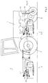
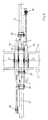
- Fig. 1 shows a mowing unit according to the invention in a side view in the direction of travel (F), the wheels of which are supported on a flat, upright plane (42).
- the mower unit shown consists of a carrier vehicle (1) with a front mower (2) coupled to the front three-point hydraulic system (23) and two on both sides of the carrier vehicle (1) between the front wheels (7) and the rear wheels (8) of the carrier vehicle (1 ) arranged side mowers (3,3 ').
- the simplified mowing units (10, 10 ', 10' '), the Side mowers (3,3 ') and that of the front mower (2) are as rotary mowers with rotating cutting tools with integrated conditioners (11, 11 ', 11' ') shown.
- the mower units (10, 10 ', 10' ') are drivable and by means of a Handlebar coupling (20) can be towed in operative connection with the carrier vehicle (1).
- the side mowers (3, 3 ') additionally have a support wheel (15, 15'), which at the end of a support wheel carrier (13, 13 ') in a pivot bearing (14) around the The vertical axis (16) is pivotally mounted, as a freely running support wheel (15, 15 ') is formed.
- the support wheel carrier (13, 13 ') is with a main carrier (12, 12 '), which is articulated laterally to the carrier vehicle (1).
- the handlebar coupling (20) consists of articulated coupling links (21,21 '), which on the one hand on the mowing units (10,10', 10 '') and on the other coupled to a boom, designed as a jack bracket boom (17, 17 ', 17' ') are.
- the coupling links (21, 21 ') are in the Mowing operations are mainly exposed to tensile forces, causing the mowing units (10,10 ', 10' ') in the forward movement of the carrier vehicle (1) in the direction of travel (F) are subject to towing.
- the jack bracket (17 '') of the front mower (2) or the jack bracket (17,17 ') of the side mowers (3,3') are part of the main carrier (12,12 ') and thus Part of the supporting structure (56,56 ') in total, on which the mowing units (10,10 ', 10' ') can be moved in height and also by one due to the link coupling (20) Roll axis are articulated rotatably to the direction of travel (F), whereby can overlay both forms of movement.
- the Handlebar coupling (20 ') due to the formation of the position of the Coupling points of the coupling links (21, 21 ') that the mowing units (10, 10', 10 ') while driving over an obstacle on the ground, such as a soil survey that the mowing units (10, 10 ', 10' ') additional and relative to the carrier vehicle (1), at the same time for changing the position can also retreat opposite to the direction of travel (F), which the Force amplitudes of the towing force of a mower currently occurring reduced.
- F direction of travel
- the front mower (2) can be in its final position with the lifting cylinder (24) Transport position to be raised
- the mowing units (10, 10, 10, '') can be used during the mowing process the lifting cylinders (19, 19 ', 19' ') are lifted off the floor For example, to be able to run over mowed green fodder without the Mowing tools are on the ground.
- each coupling link (21, 21 ') on both sides are expediently designed as ball-and-socket eyes.
- the location of the in Direction of travel (F) front connection points of the coupling links (21,21 ') as Part of a jib bracket (17, 17 ', 17' ') is fixed so that the Mowing units (10, 10 ', 10' ') while sliding over a raised ground or bottom depression largely independent of the current orientation of the jib bracket (17, 17 ', 17' ').
- the mower units (10, 10 ', 10' ') are parallel to the handlebar coupling (20) prestressed spring elements (18) with the associated Wegbockauslegern (17,17 ', 17' ') in operative connection such that a partial amount of Weight force of a cutting unit (10,10 ', 10' ') during the mowing operation of the respective jib bracket (17, 17 ', 17' ') is worn.
- the remaining part of the weight of the mowing units (10, 10 ', 10' ') is during the mowing operation from the contact areas of the mowing units (10,10 ', 10' ') supported on the floor, so that these supporting forces Represents reaction forces of the remaining partial amount of weight.
- the vertical proportion of the spring forces as the sum vector of the spring elements (18), which is the relief component for reducing the ground support forces of the Mowing units (10, 10 ', 10' ') must also act as a reaction force be supported on the ground.
- the coupling between the front mower (2) and the carrier vehicle (1) is like this designed that the vertical component of the spring forces, to relieve the Ground support force of the cutting unit (10 '') on the front wheels (7) of the Carrier vehicle (1) is supported.
- the coupling between the side mowers (3,3 ') and the carrier vehicle (1) is designed so that the vertical component of the spring forces for relief the ground support force of the mowing unit (10, 10 ') partly on the front wheels (7), partly on the rear wheels (7) of the carrier vehicle (1), and partly on the support wheels (15,15 ') of the side mowers (3,3') is supported.
- the amounts of the remaining ground support forces to support the Mowing units (10, 10 ', 10' ') opposite the ground can be cut through the The adjustability of the spring preload forces can be divided.
- Part of the handlebar coupling (20) are also the pressurizable medium Actuators, for example designed as hydraulically operated lifting cylinders (19). In the working position shown, the lifting cylinders (19) are in Floating position so that the ground adaptation of the mowing unit (10,10 ') do not hinder.
- Actuators for example designed as hydraulically operated lifting cylinders (19). In the working position shown, the lifting cylinders (19) are in Floating position so that the ground adaptation of the mowing unit (10,10 ') do not hinder.
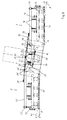
- Fig. 2 shows a self-propelled mower unit according to the invention in a side view in the direction of travel (F) with the mower units (10, 10 ', 10'') lifted off the ground.
- the mower units (10, 10 ', 10') can be transferred from the mowing position to a raised position and vice versa with the lifting cylinders (19, 19') pressurized with pressure medium.
- the mowing units (10, 10 ') can be held in the raised position, for example by pilot-operated, non-return valves.
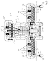
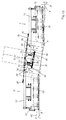
- FIG. 3 shows a self-propelled mower unit according to the invention with a carrier vehicle (1) in a simplified representation in a view (X) directed from above onto the working plane according to FIG. 1.
- Both side mowers (3, 3 ') are arranged symmetrically to the main central plane (41) running perpendicular to the roadway plane in the direction of travel (F).
- the mowers, the front mower (2) and the side mowers (3,3 ') are driven by one, for better clarity of illustration because of the combustion engine, not shown, which has the torque required to drive the mower units (10, 10', 10 '' ) for example via a transmission drive to the V-belt pulley (29) into a transfer case (30), for example designed as a bevel gear.
- a transfer case (30) for example designed as a bevel gear.
- the cardan shaft (31) represents the continuation of the drive train for driving the mowing unit (10 '') of the front mower (2)
- the cardan shaft (32) represents the continuation of the drive train for driving the mower units (10,10 ') of the side mowers (3 , 3 ').
- the transfer case (33) for example designed as a bevel gear, branches the drive train for driving the mowing units (10, 10') in such a way that from the transfer case (33) two output shafts with the articulated shafts (34, 34 '), the cardan shaft (34) representing the drive train for the mowing unit (3) and the cardan shaft (34') representing the drive train for the mowing unit (3 ').
- Both the front mower (2) and the side mowers (3,3 ') are attached to that Chassis (9) of the carrier vehicle (1) articulated.
- the carrier vehicle (1) can have a front three-point hydraulic system, as shown be equipped on which the front mower (2) is coupled.
- Both side mowers (3,3 ') are each by means of a boom arm (4,4') a hinge joint connection (25, 25 ') with predominantly Hinge axis parallel to the direction of travel as pivot axis (27, 27 ') for the Cantilever arm (4,4 '), articulated on the chassis (9) of the carrier vehicle (1).
- the cantilever arms (4,4 ') form the link between the support frame (9) of the carrier vehicle (1) and the main carrier (12, 12 ') of the side mowers (3,3 ').
- This connection is established by the extension arms (4,4 ') on the end directed outside, also by means of a hinge joint connection (26, 26 ') with predominantly hinge axis parallel to the direction of travel as pivot axis (28, 28 ') to fold up the respective side mower (3,3 ') into its respective Transport position, with the main carrier (12, 12 ') are connected.
- FIG. 4 shows the view (Y) according to FIG. 1 in a simplified but enlarged illustration.
- Two side mowers (3, 3 ') are each assigned two actuators acted upon by pressure medium, designed as pressure medium cylinders (35, 36) and (35', 36 ').
- the pressure medium cylinders (35, 36) are functionally assigned to the side mower (3) and the pressure medium cylinders (35 ', 36') are functionally assigned to the side mower (3 ').
- FIG Pressure cylinder (35 ', 36') has been dispensed with because the pressure cylinder (35 ', 36') in this representation largely from those shown Pressure cylinders (35, 36) are covered.
- the pressure medium cylinders (35,35 ') are in the articulation points (37,37') or the pressure medium cylinder (36,36 ') in the articulation points (39,39') on the Chassis (9) of the carrier vehicle (1) supported.
- the pressure medium cylinders (35, 35 ') are in the articulation points (38,38 ') on the main carriers (12,12') of the side mowers (3,3 ') or the Pressure medium cylinder (36.36 ') in the articulation points (40.40') on the Cantilever arms (4,4 ') supported.
- FIG. 5 shows the articulation of the pressure medium cylinders (35, 36) according to FIG. 4 in an enlarged representation.
- the main supports (12, 12 ') of the supporting structure (55, 55') of the mowing units (10, 10 ') are supported in the hinge joints (26, 26') with respect to the chassis (9). Accordingly, the weight forces are supported in the joints with the swivel axes (28, 28 '), which thereby simultaneously exert a torque about the swivel axis (27, 27') on the extension arms (4, 4 ').
- FIG. 5a shows a simplified graphical representation of the reaction forces (F 28 , -F 28 , F 40 , F 39 ), caused by the weight (F 28 ) using the example of the extension arm (4).
- the illustration of the bearing forces in the hinge joint connection (25) has been omitted for reasons of clarity.
- the cantilever arm (4), rotatably mounted about the pivot axis (27) in the hinge joint connection (26), has the lever arm (x 1 ) with respect to the weight (F 28 ) around the pivot axis (27) and the supporting force of the piston rod of the pressure medium cylinder ( 36) at the pivot point (40) the lever arm (y 1 ).
- the pressure medium cylinder (36, 36 ') must apply corresponding counterforces (F 40 , F 39 ) at the articulation points ( 39, 40 ), where (F 39 ) the reaction force of (F 40 ).
- These counterforces represent the cylinder support forces (F 40 , F 39 ) and these generate a hydrostatic pressure in the pressure medium cylinders (36, 36 ') which must be applied by the hydraulic system, ie it must be supported.
- FIG. 5b shows, analogously to FIG. 5a, the situation as a result of the weight (F '28 ), the reaction forces (F' 28 , -F '28 , F' 40 , F '39 ) on the extension arm (4').
- the illustration of the bearing forces in the hinge joint connection (25 ') has been omitted for reasons of clarity.
- FIG. 6 shows the view (W) according to FIG. 5. It shows the pressure medium cylinders (35, 35 ') arranged approximately parallel to one another.
- FIG. 7 shows the view (Z) according to FIG. 5. It shows the pressure medium cylinders (36, 36 ') arranged approximately parallel to one another.
- FIG. 8 shows a self-propelled mower unit according to the invention in the representation analogous to FIG. 3, the position of the pressure medium cylinders (35, 35 ') being additionally shown in this figure.
- FIG. 9 shows the representation of a self-propelled mowing unit according to the invention analogous to FIG. 4 in a non-flat terrain in the working position.
- the alignment of carrier vehicle (1) and side mowers (3, 3 ') shown is adapted to the ground horizon of the site.
- the carrier vehicle (1) has an inclination angle ( ⁇ ) with respect to the horizontal (43)
- the side mower (3) has an inclination angle ( ⁇ )
- the side mower (3 ') has an inclination angle ( ⁇ ').
- the mower combination in very uneven terrain or it can also be used for mowing embankments, for example be of advantage that the mowing unit via an adjustment and Has control device which the position of the pivot axes (28, 28 ') of the Side mowers (3,3 ') and thus change the distance to the ground and can regulate if necessary.
- This can, in particular, be independent of the current roll and / or Nodding movements of the carrier vehicle (1) along its route improve.
- the mobility of the mowing units (10, 10 ') can also be increased uneven terrain can be improved, which the force peaks of the Can reduce the drag forces of the mowing units (10, 10 ').
- the Pressure cylinder (36,36 ') can be used by this pressure cylinder for example on the piston crown and piston rod side with pressure sensors are equipped, which sensory the respective hydraulic pressures and record these values as digitized input signals Feed microprocessor. Furthermore, the respective positions of the Piston rod of the hydraulic cylinder (36, 36 ') via sensors as displacement transducers are recorded, the values thus recorded as digitized input signals can be fed to a microprocessor.
- the microprocessor can input signals in the sense of a control loop Generate output signals, which in turn relate to the respective position of the Piston rods of the hydraulic cylinder (36,36 ') can act, causing the respective cantilever arms (4,4 ') about their respective pivot axes (27,27') can be rotated, which leads to a change in the distance of the Swivel axes (28, 28 ') can be used against the floor.
- Fig. 10 shows analogous to Fig.9 that through the link coupling (20) between the cutting unit (10) and the main carrier (12), the cutting unit (10) can perform a rotational movement relative to the main carrier (12). Since the mowing unit (10) is located in front of the support wheel (15), the mowing unit (10) can experience an additional angle of inclination ( ⁇ ) due to the upstream changes in the soil horizon, for example through elevations or depressions.
- FIG. 11 shows the view (Y) according to FIG. 1 in a simplified but enlarged illustration with the side mower (3) folded up on one side in the transport position.
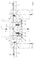
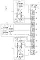
- Fig. 12 shows an embodiment of a hydraulic circuit of a self-propelled mower unit according to the invention. This figure shows a simplified hydraulic plan for controlling all hydraulic functions of the mowing unit, but without a control unit.
- This embodiment shows electrically operated directional control valves (44,44 '; 45,45'; 46,46 '; 47) to control the lifting cylinders (19,19', 19 ''; 24) and the other actuators as pressure medium cylinders (35.35 '; 36.36').
- All directional valves (44.44 '; 45.45'; 46.46 '; 47) for controlling the hydraulic Functions are arranged on a row flange plate (48), which with the Pump line (P) and the tank line (T) is connected.
- the hydrostatic Pressure is generated by a control pump (49), which from the motor (M) of the Carrier vehicle (1) is driven.
- the electrically operated directional control valves (44,44 '; 45,45'; 46,46 '; 47) have one Middle position as a blocking position, as well as two further switching positions (a and b).
- the valves are controlled, for example, with a Control panel in the driver's cabin.
- the pressure medium cylinders (36, 36 ') are hydraulic clamped, i.e. the directional control valves (45, 45 ') for controlling them are shown in Locked position switched.
- the pressure medium cylinders (35,35 ') are from the directional control valves (46,46') controlled. In the mowing mode, the valves (46, 46 ') are in Floating position, i.e. switched in the control position (a).
- the lifting cylinders (19, 19 ', 19' '; 24) are operated by the valves (44, 44', 44 '') controlled.
- the lifting cylinders (19, 19 ', 19' '; 24) are in the working position Mowing mode in floating position, i.e. they are switched in position (a).
- the mowers can by switching the Directional control valves (44, 44 ', 44' ') can be controlled individually or in groups, whereby in switch position (b) the mowing units (10, 10 ', 10' ') are lifted off the ground become.
- switch position (b) the mowing units (10, 10 ', 10' ') are lifted off the ground become.
- the middle position of the valves (44, 44 ', 44' ') are used as the blocking position the cutting units (10, 10 ', 10' ') are held in their raised position.
- the front mower (2) With the lifting cylinders (24) the front mower (2) by controlling the Directional control valve (47) raised in switch position (b). In the middle position as The front mower (2) is in the transport position when the valve (47) is locked held. In switch position (a) the front mower (2) can be compared to the Floor to be lowered.
- the pressure medium cylinders (35,35 ') for lifting the mowing units (10,10') are controlled by the directional control valves (46,46 '). In the working position The valves (46, 46 ') are in mowing mode in switch position (a) in floating position switched.
- the pressure medium cylinders (36, 36 ') are controlled by the valves (45, 45').
- the piston rods are both Hydraulic cylinder (45,45 ') clamped hydraulically, i.e. the directional control valves (45,45 ') are in the middle position as a blocking position.
- the directional control valves (45, 46; 45 ', 46') can work in groups can be controlled together.
- the directional control valves (45,45 ') are in the switch position (a) and the directional control valves (46, 46 ') are also switched to switch position (a).
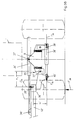
- Fig. 13 shows a further embodiment of a hydraulic circuit of a self-propelled mower unit according to the invention.
- This figure shows a simplified hydraulic plan for controlling all hydraulic functions of the mower unit with a control unit for position control of the boom arms (4,4 ').
- the control structure corresponds in principle to the description in FIG. 12.
- the pressure medium cylinders (36, 36 ') stand with the pressure sensors (50, 51); (50 ', 51') to record their current hydrostatic pressure in connection.
- the Piston rods of the pressure medium cylinders (35, 35 '); (36,36 ') stand with the incremental displacement transducers (52, 52 '); (53,53 ') for sensory detection their position in relation to their cylinder.
- the output signals of the Pressure sensors (50, 51); (50 ', 51') and the displacement transducer (52.52 ', 53.53') a microprocessor, not shown, as input signals in control-technical sense of the return.
- the hydrostatic Pressure on the piston crown side of the pressure medium cylinder (36, 36 ') provides the Control variables represent, these control variables in turn a function of the situation the piston rods can represent.
- the directional control valves (45, 45 ') according to FIG. 12 are replaced by the electrical ones actuated microprocessor-controlled servo directional valves (54, 54 ') with one each Servo pressure valve (55.55 ').
- the servo directional control valves (54, 54 ') with their servo pressure valves are now (55.55 ') including the pressure cylinder (36.36') as actuators one microprocessor controlled controlled system to support a dynamic controlled adaptation of the mowing units (10, 10 ') to the ground relief.
- the pressure sensors (50, 51) record the hydrostatic pressures on the piston rod and piston crown side, from which the differential pressure of both pressure chambers can be determined.
- the Displacement sensors (53, 53 ') determine the current position of the piston rods of the Pressure cylinder (36.36 ') and the displacement transducers (52.52') determine the Current position of the piston rods of the pressure medium cylinders (35, 35 '). This Values are available to the microprocessor as input signals, so that from this the total momentary state of the mowing units (10, 10 '), what whose orientation is in relation to the carrier vehicle, the Microprocessor is known.
- the input signals of the pressure sensors (50.51) provide information about the current force relationships at the articulation points (40.40 ') or in the swivel axes (28.28'), which leads to the vertical Load condition in the hinge joint connections (26, 26 ') closed can be.
- By actuating the servo pressure valves (55.55 ') in The momentary connection to the servo directional valves (54, 54 ') can be used Balance state of the cantilever arms (4,4 ') around the respective Swivel axes (27, 27 ') can be restored.
- This type of articulation of the mowing units (10, 10 ') in connection with the Cantilevers (4,4 ') and their support by the pressure medium cylinders (36,36') in relation to the carrier vehicle (1) in connection with the handlebar coupling (20) and the support wheel (15, 15 ') of the mowing units (10, 10') can Ground support forces of the mowing units (10, 10 ') are minimized and the given Operating conditions are set and adjusted accordingly sensitive.
- the mowing units (10, 10 ') have a good one during mowing dynamic behavior with regard to the adaptation to the soil horizon, which is equally the towing forces, especially those of the side mowers (3,3 ') minimized.
- the transmission of part of the weight of the mowing units (10, 10 ', 10' ') on support wheels (15, 15 ') increases the guide stiffness with regard to the tracking behavior of the carrier vehicle (1) overall, which is particularly favorable on the Steering behavior on slopes.
Landscapes
- Life Sciences & Earth Sciences (AREA)
- Environmental Sciences (AREA)
- Harvester Elements (AREA)
Abstract
Description
- 1 -
- Trägerfahrzeug
- 2 -
- Frontmähwerk
- 3,3' -
- Seitenmähwerk
- 4,4' -
- Auslegerarm
- 5 -
- Vorderachse
- 6 -
- Hinterachse
- 7 -
- Vorderrad
- 8 -
- Hinterrad
- 9 -
- Fahrgestell
- 10,10',10'' -
- Mähaggregat
- 11,11',11'' -
- Aufbereiter
- 12,12' -
- Hauptträger
- 13,13' -
- Stützradträger
- 14 -
- Schwenklager
- 15,15' -
- Stützrad
- 16 -
- Hochachse
- 17,17',17'' -
- Zugbockausleger
- 18 -
- Federelement
- 19,19',19'' -
- Hubzylinder
- 20 -
- Lenkerkopplung
- 21,21' -
- Koppelglied
- 22,22' -
- Tragholm
- 23 -
- Front-Dreipunkthydraulik
- 24 -
- Hubzylinder
- 25,25' -
- Scharniergelenkverbindung
- 26,26' -
- Scharniergelenkverbindung
- 27,27' -
- Schwenkachse
- 28,28' -
- Schwenkachse
- 29 -
- Keilriemenscheibe
- 30 -
- Verteilergetriebe
- 31 -
- Gelenkwelle
- 32 -
- Gelenkwelle
- 33 -
- Verteilergetriebe
- 34,34' -
- Gelenkwelle
- 35,35' -
- Druckmittelzylinder
- 36,36' -
- Druckmittelzylinder
- 37,37' -
- Gelenkpunkt
- 38,38' -
- Gelenkpunkt
- 39,39' -
- Gelenkpunkt
- 40,40' -
- Gelenkpunkt
- 41 -
- Hauptmittelebene
- 42 -
- Aufstandsebene
- 43 -
- Horizontale
- 44,44',44'' -
- Ventile
- 45,45' -
- Wegeventile
- 46,46' -
- Wegeventile
- 47 -
- Wegeventil
- 48 -
- Reihenflanschplatte
- 49 -
- Regelpumpe
- 50,50' -
- Drucksensor
- 51,51' -
- Drucksensor
- 52,52' -
- Wegaufnehmer
- 53,53' -
- Wegaufnehmer
- 54,54' -
- Servo-Wegeventil
- 55,55' -
- Servo-Druckventil
- 56,56' -
- Tragkonstruktion
- a -
- Schaltstellung
- b -
- Schaltstellung
- x1 -
- Hebelarm
- x2 -
- Hebelarm
- F -
- Fahrtrichtung
- F28, F'28 -
- Gewichtskraft
- -F28, -F'28 -
- Bodenstützkraft
- F39, F'39 -
- Zylinderstützkraft
- F40, F'40 -
- Gewichtskraft
- M -
- Motor
- P -
- Pumpenleitung
- T -
- Tankleitung
- α -
- Neigungswinkel
- β -
- Neigungswinkel
- γ -
- Neigungswinkel
- Fig. 1 -
- Mäheinheit in der Seitenansicht in Fahrtrichtung (F)
- Fig. 2 -
- Selbstfahrende Mäheinheit in der Seitenansicht in Fahrtrichtung (F) mit vom Boden abgehobenen Mähaggregaten
- Fig. 3 -
- Mäheinheit mit einem Trägerfahrzeug (1) in vereinfachter Darstellung in einer Ansicht (X) von oben auf die Arbeitsebene gerichtet gemäß Fig.1
- Fig. 4 -
- Ansicht (Y) gemäß Fig.1 in vereinfachter, vergrößerter Darstellung
- Fig. 5 -
- Anlenkung der Druckmittelzylinder (35,36) gemäß Fig.4 in vergrößerter Darstellung
- Fig. 5a -
- Vereinfachte Darstellung der Kräfte am Beispiel des Auslegerarms (4)
- Fig. 5b -
- Vereinfachte grafische Darstellung der Kräfte am Beispiel des Auslegerarms (4')
- Fig. 6 -
- Ansicht (W) gemäß Fig.5
- Fig. 7 -
- Ansicht (Z) gemäß Fig.5
- Fig. 8 -
- Mäheinheit nach der Erfindung in der Darstellung analog zu Fig.3
- Fig. 9 -
- Darstellung einer Mäheinheit nach der Erfindung analog Fig.4
- Fig. 10 -
- Eine mögliche Arbeitsstellung der Mäheinheit analog zu Fig.9
- Fig. 11 -
- Ansicht (Y) gemäß Fig. 1 in vereinfachter jedoch vergrößerter Darstellung
- Fig. 12 -
- Ausführungsbeispiel einer hydraulischen Beschaltung der Druckmittelzylinder, ohne Lageregelung
- Fig. 13 -
- Ausführungsbeispiel einer hydraulischen Beschaltung der Druckmittelzylinder, mit Lageregelung
Claims (23)
- Selbstfahrende Mäheinheit bestehend aus einem Trägerfahrzeug (1) mit einem Frontmähwerk (2) und beidseitig an dem Trägerfahrzeug (1) angelenkten Seitenmähwerken (3,3'), zum Mähen von landwirtschaftlichem Halmgut mit oder ohne Aufbereiter (11), wobei die Seitenmähwerke (3,3') zwischen den Vorder- (7) und Hinterrädern (8) seitlich auskragend an einem Auslegerarm (4,4') angeordnet und geführt sind, und die Auslegerarme (4,4') jeweils zur höhenbeweglichen Aufhängung der Seitenmähwerke (3,3') an den Tragholmen (22,22') des Fahrgestells (9) des Trägerfahrzeugs (1) um eine annähernd in Fahrt- und Arbeitsrichtung (F) des Trägerfahrzeugs (1) ausgerichtete Achse einer Scharniergelenkverbindung (25,25') schwenkbar gelagert sind, und jedes Mähaggregat (10,10') der Seitenmähwerke (3,3') gelenkig mit dem äußeren Ende des Auslegerarms (4,4') verbunden ist, und jedes Seitenmähwerk (3,3') jeweils mit seinem Auslegerarmen (4,4') mittels einer Kolben-Zylinder-Anordnung an dem Fahrgestell (9) des Trägerfahrzeugs (1) angelenkt und so mit diesem verbunden aus einer etwa horizontalen Arbeitsstellung in eine nahezu vertikale Transportstellung überführbar ist, dadurch gekennzeichnet, daßa) jedes Seitenmähwerk (3,3') einen ersten Stellantrieb als Druckmittelzylinder (35,35') zum Verschwenken eines Mähaggregates (10,10') um die Schwenkachse (27,27') zur Überführung des Seitenmähwerks (3,3') von seiner Arbeits- in seine Transportstellung und umgekehrt aufweist,b) jedes Seitenmähwerk (3,3') einen zweiten Stellantrieb als Druckmittelzylinder (36,36') zur Überbrückung der Scharniergelenkverbindung (25,25') aufweist derart, daß die Schwenkbeweglichkeit der Auslegerarme (4,4') um die Schwenkachse (27,27') wahlweise freigegeben oder unterbunden werden kann,c) jedes Seitenmähwerk (3,3') jeweils am äußeren Ende seiner Längserstreckung ein Stützrad (15) aufweist.
- Selbstfahrende Mäheinheit nach Anspruch 1, dadurch gekennzeichnet, daß jedes Seitenmähwerk (3,3') einen Ausleger (4,4') und eine Tragkonstruktion (56,56') zur gelenkigen Ankopplung eines Mähaggregats (10,10') umfaßt, dessen Ausleger (4,4') und Tragkonstruktion (56,56') mittels einer Scharniergelenkverbindung (26,26') miteinander verbunden sind, und die Tragkonstruktion (56,56') bezogen auf die Hauptmittelebene (41) außenseitig ein Stützrad (15,15') aufweist.
- Selbstfahrende Mäheinheit nach Anspruch 1 und 2, dadurch gekennzeichnet, daß die Anlenkung eines Stützrades (15,15') an die Tragkonstruktion (56,56') als Schwenklager (14) mit einer überwiegend vertikal ausgerichteten Hochachse (16) ausgebildet ist.
- Selbstfahrende Mäheinheit nach Anspruch 1 und 2, dadurch gekennzeichnet, daß die gelenkige Ankopplung eines Mähaggregats (10,10') an die Trägerkonstruktion (56,56') aus einer Lenkerkopplung (20) besteht, deren Kopplungsglieder (21,21') in ihren Kopplungspunkten einerseits mit der Tragkonstruktion (56,56') und andererseits mit dem Mähaggregat (10,10') gelenkig verbunden sind.
- Selbstfahrende Mäheinheit nach Anspruch 1 und 4, dadurch gekennzeichnet, daß die Kopplungspunkte der Kopplungsglieder (21 ,21') als Kugelgelenkverbindungen ausgebildet sind.
- Selbstfahrende Mäheinheit nach Anspruch 1 und 4, dadurch gekennzeichnet, daß die Kopplungspunkte zwischen Tragkonstruktion (56,56') und den Kopplungsgliedern (21,21') in der Arbeitsstellung Mähbetrieb bezogen auf die Fahrtrichtung (F) vor den Kopplungspunkten zwischen Tragkonstruktion (56,56') und dem Mähaggregat (10,10') angeordnet sind.
- Selbstfahrende Mäheinheit nach Anspruch 1 und 4, dadurch gekennzeichnet, daß die Kopplungspunkte zwischen Tragkonstruktion (56,56') und den Kopplungsgliedern (21,21') in der Arbeitsstellung Mähbetrieb bezogen auf die Aufstandsebene (42) oberhalb der Kopplungspunkte zwischen Tragkonstruktion (56,56') und dem Mähaggregat (10,10') angeordnet sind.
- Selbstfahrende Mäheinheit nach Anspruch 1 und 2 in Verbindung mit einem oder mehreren der Ansprüche 3 bis 7, dadurch gekennzeichnet, daß die Koppelglieder (21,21') mittels vorgespannter Federelemente (18) überbrückt sind, wodurch ein Teil der Gewichtskraft des Mähaggregats (10,10') zum einen auf das Stützrad (15,15') und zum anderen auf den Auslegerarm (4,4') abgestützt wird.
- Selbstfahrende Mäheinheit nach Anspruch 1 und 2 in Verbindung mit einem oder mehreren der Ansprüche 2 bis 8, dadurch gekennzeichnet, daß die Koppelglieder (21,21') mittels druckbeaufschlagbarer Hubzylinder (19,19') überbrückt sind, wodurch die Mähaggregate (10,10') jeweils aus ihrer Arbeitsstellung vom Boden abgehoben, in einer angehobenen Stellung arretiert und umgekehrt aus der angehobenen Stellung in die Arbeitsstellung Mähbetrieb abgesenkt werden können.
- Selbstfahrende Mäheinheit nach Anspruch 1, dadurch gekennzeichnet, daß die Scharniergelenkverbindungen (25,25') und (26,26') mit ihren Schwenkachsen (27,27') und (28,28') und die Gelenkpunkte (38,38') und (40,40') so zueinander ausgerichtet sind, daß die Druckmittelzylinder (35,36; 35',36') sowohl in der Arbeits- als auch in der Transportstellung der Seitenmähwerke (3,3') in ihrer Längserstreckung überwiegend horizontal in Bezug zur Aufstandsebene (42) ausgerichtet sind.
- Selbstfahrende Mäheinheit nach Anspruch 1 und 10, dadurch gekennzeichnet, daß die Scharniergelenkverbindungen (25,25') und (26,26') mit ihren Schwenkachse (27,27') und (28,28'), die Gelenkpunkte (38,38') und (40,40') so zueinander ausgerichtet sind, daß die Druckmittelzylinder (35,36); (35,36') sowohl in der Arbeits- als auch in der Transportstellung etwa parallel zueinander ausgerichtet sind.
- Selbstfahrende Mäheinheit nach Anspruch 1, dadurch gekennzeichnet, daß die Druckmittelzylinder (36,36') unterhalb der Verbindungslinie zwischen den Schwenkachsen (27,27') und der Aufstandsebene (42) angeordnet sind.
- Selbstfahrende Mäheinheit nach Anspruch 1, dadurch gekennzeichnet, daß die Druckmittelzylinder (35,35') oberhalb der Verbindungslinie zwischen den Schwenkachsen (27,27') und der Aufstandsebene (42) angeordnet sind.
- Selbstfahrende Mäheinheit nach Anspruch 1, dadurch gekennzeichnet, daß die Gelenkpunkte (40,40') und die Gelenkpunkte der Scharniergelenkverbindungen (25,26);(25',26') eines Auslegers (4,4') eine feste Lagebeziehung zueinander einnehmen.
- Selbstfahrende Mäheinheit nach Anspruch 1, dadurch gekennzeichnet, daß der Abstand zwischen Schwenkachse (27) und Gelenkpunkt (40) bzw. zwischen Schwenkachse (27') und Gelenkpunkt (40') kleiner ist als der Abstand zwischen Schwenkachse (27,28) bzw. (27',28').
- Selbstfahrende Mäheinheit nach Anspruch 1, dadurch gekennzeichnet, daß die Stützkraft (F40) bzw. (F'40) auf der kolbenbodenseitig eingespannten Ölsäule des Druckmittelzylinders (36,36') abgestützt ist.
- Selbstfahrende Mäheinheit nach Anspruch 1 und 16, dadurch gekennzeichnet, daß der maximale hydrostatische Druck der kolbenbodenseitig eingespannten Ölsäule durch ein Druckbegrenzungsventil begrenzt ist.
- Selbstfahrende Mäheinheit nach Anspruch 1 und 16, dadurch gekennzeichnet, daß der hydrostatische Druck der kolbenbodenseitig eingespannten Ölsäule steuerbar geregelt ist.
- Selbstfahrende Mäheinheit nach Anspruch 1 und 16, dadurch gekennzeichnet, daß der hydrostatische Druck der kolbenbodenseitig eingespannten Ölsäule steuerbar im Sinne einer Regelstrecke geregelt ist.
- Selbstfahrende Mäheinheit nach Anspruch 1 und 16, dadurch gekennzeichnet, daß der hydrostatische Druck der kolbenbodenseitig eingespannten Ölsäule steuerbar im Sinne einer mikroprozessorgesteuerten Regelstrecke geregelt ist.
- Selbstfahrende Mäheinheit nach Anspruch 1, dadurch gekennzeichnet, daß der Antriebsstrang zum Antrieb der Mähaggregate (10,10',10'') ein erstes Verteilergetriebe (30) im vorderen Bereich des Trägerfahrzeugs (1) und ein zweites Verteilergetriebe (33) im mittleren Bereich des Trägerfahrzeugs (1) derart umfaßt, daß das erste Verteilergetriebe (30) das Eingangsgetriebe zur Einleitung des Antriebsdrehmomentes aller Mähaggregate (10,10',10'') darstellt, und dieses Verteilergetriebe (30) zwei Abtriebswellen beinhaltet, zum einen eine Abtriebswelle zum Antrieb des Mähaggregats (10'') des Frontmähwerks (2) und zum anderen eine Abtriebswelle zum Antrieb des zweiten Verteilergetriebes (33) zum Antrieb der Mähaggregate (10,10') der Seitenmähwerke (3,3').
- Selbstfahrende Mäheinheit nach Anspruch 1, dadurch gekennzeichnet, daß das Verteilergetriebe (30) innerhalb des Bereiches zwischen Frontmähwerk (1) und der Vorderachse (5) des Trägerfahrzeugs (1) angeordnet ist.
- Selbstfahrende Mäheinheit nach Anspruch 1, dadurch gekennzeichnet, daß das Verteilergetriebe (33) in Bezug auf die Fahrtrichtung (F) zwischen der Vorderachse (5) und der Hinterachse (6) des Trägerfahrzeugs (1) angeordnet ist.
Applications Claiming Priority (4)
| Application Number | Priority Date | Filing Date | Title |
|---|---|---|---|
| DE19914620 | 1999-03-31 | ||
| DE19914620 | 1999-03-31 | ||
| DE19953380 | 1999-11-06 | ||
| DE19953380A DE19953380A1 (de) | 1999-03-31 | 1999-11-06 | Selbstfahrende Mäheinheit |
Publications (2)
| Publication Number | Publication Date |
|---|---|
| EP1040751A2 true EP1040751A2 (de) | 2000-10-04 |
| EP1040751A3 EP1040751A3 (de) | 2002-04-10 |
Family
ID=26052685
Family Applications (1)
| Application Number | Title | Priority Date | Filing Date |
|---|---|---|---|
| EP00100153A Withdrawn EP1040751A3 (de) | 1999-03-31 | 2000-01-10 | Selbstfahrende Mäheinheit |
Country Status (1)
| Country | Link |
|---|---|
| EP (1) | EP1040751A3 (de) |
Cited By (3)
| Publication number | Priority date | Publication date | Assignee | Title |
|---|---|---|---|---|
| FR2837347A1 (fr) * | 2002-03-21 | 2003-09-26 | Kuhn Sa | Faucheuse agricole comportant un vehicule porteur et plusieurs unites de travail |
| CN109197113A (zh) * | 2018-11-12 | 2019-01-15 | 南京林业大学 | 一种自走式底盘可升降割草机 |
| EP3837953A1 (de) * | 2019-12-19 | 2021-06-23 | AGCO International GmbH | Landwirtschaftliche vorrichtung |
Citations (1)
| Publication number | Priority date | Publication date | Assignee | Title |
|---|---|---|---|---|
| EP0808556A1 (de) | 1996-05-20 | 1997-11-26 | Maschinenfabrik Bernard Krone GmbH | Aufhängung und Antriebsanordnung für ein- oder beidseitig an einem Trägerfahrzeug angebrachte Arbeitsaggregate |
Family Cites Families (7)
| Publication number | Priority date | Publication date | Assignee | Title |
|---|---|---|---|---|
| US2936561A (en) * | 1958-09-09 | 1960-05-17 | Toro Mfg Corp | Gang mower assembly for utility tractors |
| US4864805A (en) * | 1987-09-04 | 1989-09-12 | The Toro Company | System for supporting a working unit |
| FR2642610B1 (fr) * | 1989-02-07 | 1991-05-17 | Kuhn Sa | Faucheuse avec dispositif de securite a declenchement |
| DE4013591A1 (de) * | 1990-04-27 | 1991-10-31 | Poettinger Alois Landmasch | Landwirtschaftliche maschine |
| DE4405858C1 (de) * | 1994-02-23 | 1995-06-01 | Fortschritt Erntemaschinen | Aufhängung für ein- oder beidseitig an einem Trägerfahrzeug angebrachte Arbeitsaggregate |
| DE29719765U1 (de) * | 1997-11-07 | 1998-12-17 | Maschinenfabrik Bernard Krone GmbH, 48480 Spelle | Aufhängung für beidseitig an einem Trägerfahrzeug angebrachte Arbeitsaggregate |
| DE29816837U1 (de) * | 1998-09-19 | 1998-11-26 | Maschinenfabriken Bernard Krone Gmbh, 48480 Spelle | Arbeitsaggregatekombination an einem selbstfahrenden Trägerfahrzeug |
-
2000
- 2000-01-10 EP EP00100153A patent/EP1040751A3/de not_active Withdrawn
Patent Citations (1)
| Publication number | Priority date | Publication date | Assignee | Title |
|---|---|---|---|---|
| EP0808556A1 (de) | 1996-05-20 | 1997-11-26 | Maschinenfabrik Bernard Krone GmbH | Aufhängung und Antriebsanordnung für ein- oder beidseitig an einem Trägerfahrzeug angebrachte Arbeitsaggregate |
Cited By (9)
| Publication number | Priority date | Publication date | Assignee | Title |
|---|---|---|---|---|
| FR2837347A1 (fr) * | 2002-03-21 | 2003-09-26 | Kuhn Sa | Faucheuse agricole comportant un vehicule porteur et plusieurs unites de travail |
| WO2003079761A1 (fr) * | 2002-03-21 | 2003-10-02 | Kuhn, S.A. | Faucheuse agricole comportant un vehicule porteur et plusieurs unites de travail |
| US7500341B2 (en) | 2002-03-21 | 2009-03-10 | Kuhn S.A. | Agricultural cutter comprising a carrier vehicle and several work units |
| US8074432B2 (en) | 2002-03-21 | 2011-12-13 | Kuhn S.A. | Agricultural mower comprising a carrying vehicle and several work units |
| US8220233B2 (en) | 2002-03-21 | 2012-07-17 | Kuhn S.A. | Agricultural mower comprising a carrying vehicle with four steering and driving wheels and plural pivotable front and lateral work units |
| US8225588B2 (en) | 2002-03-21 | 2012-07-24 | Kuhn S.A. | Agricultural mower comprising a carrying vehicle with plural pivotable front and lateral work units and a height adjustable front hitching device |
| CN109197113A (zh) * | 2018-11-12 | 2019-01-15 | 南京林业大学 | 一种自走式底盘可升降割草机 |
| CN109197113B (zh) * | 2018-11-12 | 2023-10-17 | 南京林业大学 | 一种自走式底盘可升降割草机 |
| EP3837953A1 (de) * | 2019-12-19 | 2021-06-23 | AGCO International GmbH | Landwirtschaftliche vorrichtung |
Also Published As
| Publication number | Publication date |
|---|---|
| EP1040751A3 (de) | 2002-04-10 |
Similar Documents
| Publication | Publication Date | Title |
|---|---|---|
| EP1808064B1 (de) | Selbstfahrendes Grossflächenmähwerk | |
| EP2042011B1 (de) | Arbeitsfahrzeug mit Anbauvorrichtung | |
| DE2053073B2 (de) | Mähmaschine | |
| DE8916172U1 (de) | Mäh- und Heumaschine | |
| DE102021123337A1 (de) | Selbstfahrende Erntemaschine mit einer höhenverstellbaren Aufnahmevorrichtung | |
| EP1048195B1 (de) | Schwenkeinrichtung für Stützräder | |
| EP0266785A1 (de) | Selbstfahrendes Vielzweckgerät | |
| EP1407653A2 (de) | Vorrichtung zum Regeln der Position eines Anbaugeräts relativ zu einem Trägerfahrzeug | |
| EP1093707A1 (de) | Selbstfahrendes landwirtschaftliches Fahrzeug | |
| DE19919959A1 (de) | Fahrwerkanordnung | |
| EP2436260A1 (de) | Heuwerbungsmaschine zum Wenden von am Boden liegendem Erntegut | |
| EP3603374A1 (de) | Landwirtschaftliche arbeitsmaschine | |
| DE19953380A1 (de) | Selbstfahrende Mäheinheit | |
| EP4019301A1 (de) | Spurweitenveränderliche achsvorrichtung, spezialfahrzeug und verwendung desselben | |
| DE102015108505A1 (de) | Aufsattelpflug | |
| EP3242543B1 (de) | Landwirtschaftliches arbeitsgerät mit zusatzfahrwerk | |
| EP2710869B1 (de) | Geräteanbauvorrichtung eines Arbeitsfahrzeugs | |
| EP0945051B1 (de) | Mähmaschine | |
| EP1040751A2 (de) | Selbstfahrende Mäheinheit | |
| DE69504081T2 (de) | Schlepper-aufgehangene mähmaschine | |
| DE4105287A1 (de) | Vorrichtung fuer fahrzeuge und maschinen | |
| EP1394021B1 (de) | Stützradanordnung für Fahrzeug | |
| EP0698338B1 (de) | Erntemaschine mit Seitenhangausgleich | |
| EP4124221B1 (de) | Landwirtschaftliche maschine und landwirtschaftliche maschinenkombination | |
| EP3971066B1 (de) | Traktor mit raupenlaufwerk |
Legal Events
| Date | Code | Title | Description |
|---|---|---|---|
| PUAI | Public reference made under article 153(3) epc to a published international application that has entered the european phase |
Free format text: ORIGINAL CODE: 0009012 |
|
| AK | Designated contracting states |
Kind code of ref document: A2 Designated state(s): AT BE CH CY DE DK ES FI FR GB GR IE IT LI LU MC NL PT SE Kind code of ref document: A2 Designated state(s): AT DE FR NL |
|
| AX | Request for extension of the european patent |
Free format text: AL;LT;LV;MK;RO;SI |
|
| PUAL | Search report despatched |
Free format text: ORIGINAL CODE: 0009013 |
|
| AK | Designated contracting states |
Kind code of ref document: A3 Designated state(s): AT BE CH CY DE DK ES FI FR GB GR IE IT LI LU MC NL PT SE |
|
| AX | Request for extension of the european patent |
Free format text: AL;LT;LV;MK;RO;SI |
|
| 17P | Request for examination filed |
Effective date: 20020620 |
|
| AKX | Designation fees paid |
Free format text: AT DE FR NL |
|
| GRAP | Despatch of communication of intention to grant a patent |
Free format text: ORIGINAL CODE: EPIDOSNIGR1 |
|
| STAA | Information on the status of an ep patent application or granted ep patent |
Free format text: STATUS: THE APPLICATION IS DEEMED TO BE WITHDRAWN |
|
| 18D | Application deemed to be withdrawn |
Effective date: 20040603 |