EP1040331B1 - Capteurs a fibres optiques - Google Patents
Capteurs a fibres optiques Download PDFInfo
- Publication number
- EP1040331B1 EP1040331B1 EP98967075A EP98967075A EP1040331B1 EP 1040331 B1 EP1040331 B1 EP 1040331B1 EP 98967075 A EP98967075 A EP 98967075A EP 98967075 A EP98967075 A EP 98967075A EP 1040331 B1 EP1040331 B1 EP 1040331B1
- Authority
- EP
- European Patent Office
- Prior art keywords
- fibre
- sensor
- bending
- housing
- tube
- Prior art date
- Legal status (The legal status is an assumption and is not a legal conclusion. Google has not performed a legal analysis and makes no representation as to the accuracy of the status listed.)
- Expired - Lifetime
Links
- 238000005452 bending Methods 0.000 title claims description 60
- 239000000835 fiber Substances 0.000 claims description 44
- 238000004873 anchoring Methods 0.000 claims description 20
- 239000013307 optical fiber Substances 0.000 claims description 18
- 230000001419 dependent effect Effects 0.000 claims description 3
- 239000003292 glue Substances 0.000 claims description 2
- 230000003287 optical effect Effects 0.000 claims description 2
- 238000010276 construction Methods 0.000 description 14
- 230000000694 effects Effects 0.000 description 8
- 238000005259 measurement Methods 0.000 description 6
- 238000012544 monitoring process Methods 0.000 description 5
- 238000004026 adhesive bonding Methods 0.000 description 1
- 238000006073 displacement reaction Methods 0.000 description 1
- 239000011521 glass Substances 0.000 description 1
- 230000002706 hydrostatic effect Effects 0.000 description 1
- 230000006698 induction Effects 0.000 description 1
- 238000004519 manufacturing process Methods 0.000 description 1
- 239000000463 material Substances 0.000 description 1
- 239000002184 metal Substances 0.000 description 1
- 238000000034 method Methods 0.000 description 1
- 239000007787 solid Substances 0.000 description 1
- XLYOFNOQVPJJNP-UHFFFAOYSA-N water Substances O XLYOFNOQVPJJNP-UHFFFAOYSA-N 0.000 description 1
Images


Classifications
-
- G—PHYSICS
- G01—MEASURING; TESTING
- G01B—MEASURING LENGTH, THICKNESS OR SIMILAR LINEAR DIMENSIONS; MEASURING ANGLES; MEASURING AREAS; MEASURING IRREGULARITIES OF SURFACES OR CONTOURS
- G01B11/00—Measuring arrangements characterised by the use of optical techniques
- G01B11/16—Measuring arrangements characterised by the use of optical techniques for measuring the deformation in a solid, e.g. optical strain gauge
- G01B11/18—Measuring arrangements characterised by the use of optical techniques for measuring the deformation in a solid, e.g. optical strain gauge using photoelastic elements
-
- G—PHYSICS
- G01—MEASURING; TESTING
- G01D—MEASURING NOT SPECIALLY ADAPTED FOR A SPECIFIC VARIABLE; ARRANGEMENTS FOR MEASURING TWO OR MORE VARIABLES NOT COVERED IN A SINGLE OTHER SUBCLASS; TARIFF METERING APPARATUS; MEASURING OR TESTING NOT OTHERWISE PROVIDED FOR
- G01D5/00—Mechanical means for transferring the output of a sensing member; Means for converting the output of a sensing member to another variable where the form or nature of the sensing member does not constrain the means for converting; Transducers not specially adapted for a specific variable
- G01D5/26—Mechanical means for transferring the output of a sensing member; Means for converting the output of a sensing member to another variable where the form or nature of the sensing member does not constrain the means for converting; Transducers not specially adapted for a specific variable characterised by optical transfer means, i.e. using infrared, visible, or ultraviolet light
- G01D5/32—Mechanical means for transferring the output of a sensing member; Means for converting the output of a sensing member to another variable where the form or nature of the sensing member does not constrain the means for converting; Transducers not specially adapted for a specific variable characterised by optical transfer means, i.e. using infrared, visible, or ultraviolet light with attenuation or whole or partial obturation of beams of light
- G01D5/34—Mechanical means for transferring the output of a sensing member; Means for converting the output of a sensing member to another variable where the form or nature of the sensing member does not constrain the means for converting; Transducers not specially adapted for a specific variable characterised by optical transfer means, i.e. using infrared, visible, or ultraviolet light with attenuation or whole or partial obturation of beams of light the beams of light being detected by photocells
- G01D5/353—Mechanical means for transferring the output of a sensing member; Means for converting the output of a sensing member to another variable where the form or nature of the sensing member does not constrain the means for converting; Transducers not specially adapted for a specific variable characterised by optical transfer means, i.e. using infrared, visible, or ultraviolet light with attenuation or whole or partial obturation of beams of light the beams of light being detected by photocells influencing the transmission properties of an optical fibre
- G01D5/35383—Mechanical means for transferring the output of a sensing member; Means for converting the output of a sensing member to another variable where the form or nature of the sensing member does not constrain the means for converting; Transducers not specially adapted for a specific variable characterised by optical transfer means, i.e. using infrared, visible, or ultraviolet light with attenuation or whole or partial obturation of beams of light the beams of light being detected by photocells influencing the transmission properties of an optical fibre using multiple sensor devices using multiplexing techniques
-
- G—PHYSICS
- G01—MEASURING; TESTING
- G01L—MEASURING FORCE, STRESS, TORQUE, WORK, MECHANICAL POWER, MECHANICAL EFFICIENCY, OR FLUID PRESSURE
- G01L1/00—Measuring force or stress, in general
- G01L1/24—Measuring force or stress, in general by measuring variations of optical properties of material when it is stressed, e.g. by photoelastic stress analysis using infrared, visible light, ultraviolet
- G01L1/242—Measuring force or stress, in general by measuring variations of optical properties of material when it is stressed, e.g. by photoelastic stress analysis using infrared, visible light, ultraviolet the material being an optical fibre
- G01L1/246—Measuring force or stress, in general by measuring variations of optical properties of material when it is stressed, e.g. by photoelastic stress analysis using infrared, visible light, ultraviolet the material being an optical fibre using integrated gratings, e.g. Bragg gratings
Definitions
- the present invention concerns a device for measuring a bending load in constructions, according to the introductory part of Claim 1.
- a Bragg grating is a single mode fibre having permanent periodical variation in the refraction index over a fibre length of for example 0.1 to 10 cm. Variation in the refraction index is established by illuminating the fibre with an UV-laser.
- a bragg grating reflects light at a wave length given by the refraction index and the period related to space for the variation in refraction index (grating period), while light outside this wave period will pass the grating more or less unhindered.
- the light reflected by the Bragg grating will give a wave length which varies as a function of a measuring dimension changing the refraction index of the fibre material in the grating and/or by the fibre length in the grating zone (the grating period). Tension in the fibre or temperature will thus give a change in wavelength for the light reflected in the Bragg grating.
- temperature can be measured in the range -100 °C to +250 °C at approximately 20 points along a fibre having a length of 50-100 km. Using various multiplexing techniques, the number of measurement points can be increased. Examples of areas of application are temperature surveillance of power cables, pipelines, electrical transformers, engines and temperature monitoring of industrial processes.
- US4,761,073 discloses a distributed, spatially resolving optical fibre strain gauge.
- US5,684,297 discloses a distributed optical sensor for detecting and/or measuring changes in physical magnitudes such as temperature, pressure and mechanical reformation.
- the objective of the present invention is to provide a device for measuring bending in and on mechanical constructions.
- a device for measuring bending in mechanical constructions comprising:
- the Bragg-grating in the first sensor will be influenced by bending, tension and thermal effects.
- the Bragg-grating in the second sensor will mainly is only influenced by tension and thermal effects (for example expansion in the second sensor), while the Bragg-grating in the third sensor only is influenced by thermal effects.
- the principal design of a bend measuring sensor according to the present invention renders it possible to produce bend measuring sensors with very small dimensions capable of measuring both small and large bending radii from distant positions.
- the device also has the capability of measuring bending in different positions along the same optical fibre.
- FIG. 1 shows a first embodiment of a first sensor according to the present invention.
- This first sensor includes a generally cylindrical housing 101 with an inner cylindrical bore 102. Inside the bore is arranged an optical fibre 120 prestressed between a first and second anchoring point 110, 111.
- a first Bragg grating 121 which in reality is integrated into the optical fibre 120, is in the figure, for ease of reference, indicated as a hatched rectangle, located on the freely prestressed fibre section.
- Fig. 1a shows the bending sensor and location of the fibre 120 and grating 121 when the housing 101 is being strongly bent.
- the bore 102 has an inner diameter which is sufficiently large for the grating so that it is not exposed to tension load during strong bending. The length and diameter of the housing will vary with the particular area of use.
- the Bragg grating 121 will be relaxed, where as the light reflected from the Bragg grating 121 will be influenced by bending, tension and thermal effects from the surrounding atmosphere and from the next construction, which is to be measured.
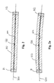
- Fig. 2 shows an embodiment of a second sensor for use in a device according to the present invention, and comprises a generally cylindrical housing 103 having an inner cylindrical bore 104.
- the housing 103 can, for the second sensor, be attached to the first housing 101 at the anchoring point 111.
- Inside the bore 104 in the second sensor is located an optical fibre 120 prestressed between the anchoring points 111 and 112.
- the bore 104 has an inner diameter slightly larger then the external diameter of the fibre 120. which then forces the fibre 120 with the grating 122 to follow the axis in the housing 103 in bending the same.
- Fig. 2a shows this second sensor during strong bending.
- the Bragg grating will be curved in step with the housing 103, and thus not relaxed as a result of the bending. Light reflected from this Bragg grating 122 will then only be influenced by tension and thermal effects from the surrounding atmosphere and from the next construction which is to be measured.
- Fig. 3 shows an embodiment of a third sensor for use in a device according to the present invention.
- the third sensor comprises a generally cylindrical housing 105 having an inner cylindrical bore 106.
- the housing 105 can be attached to the second sensor at anchoring point 112.
- Inside the bore 106 in the third sensor is located an optical fibre 120 mounted unstressed between a first and second anchoring point 112 and 113 located at respective ends of the housing 105.
- the third Bragg grating is located in the fibre section which is suspended between the anchoring points 112 and 113.
- the bore 106 has (like bore 102 of the first sensor) an inner diameter which is sufficiently large enough not to expose the grating to a tension load during bending that is too large. Since the fibre 120 of the third sensor is not prestressed, it will not be relaxed at the initial bending. Length and diameter of the housing will vary with the particular area of use.
- the Bragg grating 123 in the optical fibre section that is not prestressed will only to a small degree be exposed to load from bending and tension of the housing.
- Bragg grating 123 will be substantially effected from changes in temperature caused by the surrounding atmosphere or the next construction which is to be measured. In this way, the device can be compensated for temperature-caused displacement in the wave length in light reflected from the Bragg grating 123.
- the device according to present invention is calibrated at different temperatures in order to achieve a best possible temperature dependent measurement of wavelength-shift as a function of bending.
- An alternative for avoiding mechanical influence of the grating 123 in the third sensor used for temperature compensation is to connect it to, for example, a tube 107 by means of a glue joint, as shown in Fig. 4.
- the tube 107 (not connected to the housing 105) will then isolate the grating 123 from bending and tension as shown in Fig. 4a.
- the tube 107 can be a metallic tube or alternatively a glass rod with grooves for the optical fibre.
- Fig. 5 shows a device according to the present invention with first, second and third sensors each with different responses to bending integrated in the device.
- the device comprises a longitudinal housing 150, for example in the shape of a tube, with the respective sensors distributed along the length of the housing 150 and situated next to each other.
- the housing 150 accomodated the respective sensors 101, 102 and 103.
- the housing 150 is connected externally to a surrounding mechanical construction (to be measured for bending) over the entire length (for example by gluing) or at the anchoring points 110, 111, 112 and 113.
- first Bragg grating 121 When the housing 101 is bent, first Bragg grating 121 will shorten because the fibre is situated in a straight length between the anchoring points 110 and 111.
- the second Bragg grating 122 in the bore 104 will experience a substantially smaller change in length because it is forced to follow the axis of the housing.
- the third grating will not be influenced by bending of the construction.
- the housing for all sensor means in this embodiment is carried out as a common tube.
- the second sensor means is carried out by locating a cannula tube 103 with support rings 131 and 132 along the axis.
- the fibre can also be protected on both sides of the bending sensor with cannula tubes 130 and 131, whichhen consitutes a small and solid cable.
- the second grating 122 will not experience the longitudinal force due to bending.
- the housing 101, 102 and 103 is glued to the surrounding construction over the entire length and is exposed to tension in addition to bending, the relative prolongation of the housings ⁇ H will be the same as in the surrounding construction. This will give the same contribution to all of the housings.
- the entire device in made of metal, except for, of course, the optical fibre.
- both housing 101, 103, 105 and inner tube 107 arc made from cannula tubes.
- the bending sensor can be constructed with a housing and tubes diameter of mere millimeters.
- the various components do not necessarily have the geometry showed by the drawings.
- the member to be exposed to bending may have a cross-section that deviates from a circular shape; it may be oval, square etc. The same applies to the other components.
- the central issue with the invention is, however, that the member to be exposed to bending shall be able to transmit length change further to the connected Bragg grating.
- the invention thus provides a device for measuring bending in mechanical constructions, which enables measurement over a broad range of stresses, with high precision and which simultanously compensates for deviations caused by temperature fluctuations.
- the device according to the present invention can be designed to be very small and can therefore be installed in places where bending measurement usually has not been possible.
- Another advantage with the device according to the invention is that the fibre is not exposed to external hydrostatic pressure, and will therefore exhibit a high reliability. Finally, this design does not require pressure tight connections for the fibre.
Landscapes
- Physics & Mathematics (AREA)
- General Physics & Mathematics (AREA)
- Optical Transform (AREA)
Claims (17)
- Dispositif de mesure des charges de flexion, caractérisé en ce que le dispositif comprend un premier capteur pour mesurer une charge de flexion, ledit capteur comprenant:un premier membre (101) qui peut être soumis à flexion; etune fibre optique (120) montée par rapport audit premier membre au premier et deuxième point d'ancrage (110, 111) de sorte que la fibre (120) est précontrainte,dans lequel la fibre (120) comporte un premier réseau de Bragg (121), agencé dans la fibre (120) précontrainte, et dans lequel le premier membre (101) est agencé de façon à ce que lorsque le premier membre (101) est fléchi, la tension dans la fibre (120) est réduite.
- Dispositif selon la revendication 1, dans lequel le premier membre (101) comprend un premier boîtier (101), la fibre (120) étant connectée au premier boîtier (101) audit premier et deuxième point d'ancrage (110, 111).
- Dispositif selon la revendication 2, dans lequel le premier boîtier (101) est agencé de telle façon que la fibre (120) n'est pas mise en contact avec celui-ci, lorsque le premier boîtier est exposé à une force de flexion.
- Dispositif selon la revendication 2 ou 3, dans lequel le premier boîtier (101) a une forme généralement cylindrique.
- Dispositif selon une quelconque des revendications précédentes, dans lequel le dispositif comprend en outre un deuxième capteur pour mesurer les charges de tension, le deuxième capteur comprenant un deuxième membre (103) qui peut être soumis à flexion, une fibre optique (120) étant montée par rapport au deuxième membre (103) au premier et deuxième point d'ancrage (111, 112) de sorte que la fibre (120) est précontrainte, la fibre (120) étant fournie d'un deuxième réseau de Bragg (122) positionné dans la fibre précontrainte (120), le deuxième membre (103) étant agencé de façon à ce que la fibre (120) soit fléchie ensemble avec le deuxième membre (103) lorsque le deuxième membre (103) est fléchi.
- Dispositif selon la revendication 5, caractérisé en ce que le deuxième membre (103) est agencé avec un élément (103, 104) forçant la fibre (120) à se fléchir ensemble avec le deuxième membre (103).
- Dispositif selon la revendication 6, dans lequel l'élément (103, 104) est un tube (103), de préférence un tube (103) avec un diamètre de quelques millimètres, agencé entre les deux points d'ancrage (111, 112) de sorte que les propriétés de flexion soient approximativement les mêmes sur la longueur dudit tube (103).
- Dispositif selon l'une quelconque des revendications précédentes, comprenant en outre un troisième capteur pour mesurer la température, le troisième capteur comprenant un troisième membre (105) qui peut être soumis à flexion, une fibre optique (120) étant suspendue par rapport au premier et deuxième point d'ancrage (112, 113) de sorte que la fibre (120) n'est pas précontrainte, dans lequel la fibre (120) comporte un troisième réseau de Bragg (123), positionné dans la fibre suspendue (120), le troisième membre (105) étant agencé de façon à ce que, lorsque le troisième membre (105) est fléchi ou exposé à une charge de tension, la fibre (120) n'est ni mise en contact avec le troisième membre ni exposé à une charge de tension.
- Dispositif selon la revendication 8, caractérisé en ce que le troisième réseau de Bragg (123) positionné dans le troisième capteur, est agencé dans un tube à suspension libre (107) en vue de réduire l'influence de la flexion et de la tension sur le réseau (123).
- Dispositif selon l'une quelconque des revendications 5 à 9, dans lequel, lorsque fournis, les deuxième et/ou troisième membres (103, 105) comprennent un deuxième et/ou troisième boîtier (103, 105) respectivement.
- Dispositif selon l'une quelconque des revendications précédentes, dans lequel le premier membre (101) et/ou, lorsque fournis, un quelconque deuxième et troisième membres (103, 105) ou ledit élément (103, 104) comprend un tube, de préférence un tube avec un diamètre de quelques millimètres.
- Dispositif selon l'une quelconque des revendications précédentes, dans lequel n'importe quel point d'ancrage (110, 111, 112, 113) du premier capteur et/ou, lorsque fournis, le deuxième et troisième capteur, sont des joints de colle.
- Dispositif selon l'une quelconque des revendications précédentes, comprenant un boîtier global (150), dans lequel est positionné le premier capteur et, lorsque fournis, au moins l'un des deuxième et troisième capteurs.
- Dispositif selon la revendication 13, directement ou indirectement dépendante de la revendication 7, dans lequel ledit tube (103) est agencé dans le boîtier global (150) et est supporté par un ou plusieurs éléments en forme d'anneau (132, 133) contre la partie interne du boîtier global (150).
- Dispositif selon la revendication 13 ou 14, comprenant en outre les tubes (130, 131) connectés aux extrémités respectives du boîtier global (150), en vue de porter la fibre optique (120) et de protéger la fibre (120) et l'intérieur du dispositif contre l'environnement.
- Dispositif selon l'une quelconque des revendications 13 à 15, dans lequel le premier capteur et, lorsque fournis, l'un ou les deux du deuxième et troisième capteur sont agencés séquentiellement dans ledit boîtier global (150).
- Dispositif selon l'une quelconque des revendications précédentes, dans lequel les fibres optiques dudit premier capteur et, lorsque fournis, au moins un dudit deuxième et dudit troisième capteur sont des parties de la fibre optique commune (120).
Applications Claiming Priority (3)
| Application Number | Priority Date | Filing Date | Title |
|---|---|---|---|
| WOPCT/NO97/05657 | 1997-12-05 | ||
| NO19975657A NO307314B1 (no) | 1997-12-05 | 1997-12-05 | Anordning for registrering av boyebelastning |
| PCT/NO1998/000359 WO1999032862A1 (fr) | 1997-12-05 | 1998-12-03 | Capteurs a fibres optiques |
Publications (2)
| Publication Number | Publication Date |
|---|---|
| EP1040331A1 EP1040331A1 (fr) | 2000-10-04 |
| EP1040331B1 true EP1040331B1 (fr) | 2007-11-28 |
Family
ID=19901415
Family Applications (1)
| Application Number | Title | Priority Date | Filing Date |
|---|---|---|---|
| EP98967075A Expired - Lifetime EP1040331B1 (fr) | 1997-12-05 | 1998-12-03 | Capteurs a fibres optiques |
Country Status (6)
| Country | Link |
|---|---|
| US (1) | US6384404B1 (fr) |
| EP (1) | EP1040331B1 (fr) |
| DE (1) | DE69838799D1 (fr) |
| DK (1) | DK1040331T3 (fr) |
| NO (1) | NO307314B1 (fr) |
| WO (1) | WO1999032862A1 (fr) |
Families Citing this family (30)
| Publication number | Priority date | Publication date | Assignee | Title |
|---|---|---|---|---|
| NO310125B1 (no) | 1999-05-06 | 2001-05-21 | Leiv Eiriksson Nyfotek As | System for overvåking av höyspentkabler i luftstrekk |
| WO2001013060A1 (fr) * | 1999-08-13 | 2001-02-22 | Advanced Sensor Technologies Llc | Systeme de detection de la position d'une sonde a utiliser dans une machine de mesure des coordonnees |
| US6600149B2 (en) * | 1999-12-27 | 2003-07-29 | Whitten L. Schulz | Fiber grating environmental sensing system |
| JP3519333B2 (ja) * | 2000-02-10 | 2004-04-12 | エヌ・ティ・ティ・アドバンステクノロジ株式会社 | 光ファイバセンサ |
| EP1340061A4 (fr) * | 2000-12-07 | 2005-01-19 | Univ Nanyang | Detecteur de force pour fibre optique |
| BE1013983A3 (nl) * | 2001-02-27 | 2003-01-14 | Voet Marc | Optische kabel voor het meten van temperatuur en/of rek. |
| FR2823299B1 (fr) * | 2001-04-04 | 2003-09-19 | Commissariat Energie Atomique | Extensometre a longue base, a fibre optique tendue et reseau de bragg, et procede de fabrication de cet extensometre |
| GB0127497D0 (en) * | 2001-11-15 | 2002-01-09 | Secr Defence | Strain sensor |
| FR2844576B1 (fr) | 2002-09-18 | 2004-11-12 | Coflexip | Procede et dispositif de surveillance de la tenu d'une conduite flexible au niveau d'un embout terminal |
| US6840114B2 (en) * | 2003-05-19 | 2005-01-11 | Weatherford/Lamb, Inc. | Housing on the exterior of a well casing for optical fiber sensors |
| CA2443876C (fr) * | 2003-10-02 | 2007-08-21 | Fulgor Greek Electric Cables S.A. | Joint souple fabrique en usine pour tubes metalliques contenant des fibres optiques detachees et methode de fabrication de ce joint |
| US7813598B2 (en) * | 2004-01-23 | 2010-10-12 | Lm Glasfiber A/S | Device including a system adapted for use in temperature compensation of strain measurements in fibre-reinforced structures |
| KR100666379B1 (ko) | 2004-04-08 | 2007-01-10 | 박현수 | 광섬유격자 구조체 및 이를 적용한 구조물 변형 측정 장치 및 방법 |
| US7411176B2 (en) * | 2005-01-26 | 2008-08-12 | National Central University | Method and apparatus for examining corrosion of tendon embedded in concrete |
| JP2007108325A (ja) * | 2005-10-12 | 2007-04-26 | Oki Electric Ind Co Ltd | 波長調整装置および波長調整方法 |
| GB2440954B (en) * | 2006-08-18 | 2008-12-17 | Insensys Ltd | Structural monitoring |
| WO2008090348A1 (fr) * | 2007-01-24 | 2008-07-31 | Gkn Aerospace Services Limited | Détection de la température |
| KR101267261B1 (ko) | 2008-10-09 | 2013-05-23 | (주)카이센 | 에프비지 광섬유센서 온도 케이블 |
| DE102009007142A1 (de) | 2009-02-02 | 2010-08-05 | Draka Industrial Cable Gmbh | Faseroptische Messvorrichtung |
| WO2010138813A2 (fr) * | 2009-05-29 | 2010-12-02 | The Board Of Trustees Of The University Of Illinois | Capteur de fissure/grand déplacement à haute résolution |
| GB201018538D0 (en) | 2010-11-03 | 2010-12-15 | Wellstream Int Ltd | Parameter sensing |
| FR2998662B1 (fr) * | 2012-11-23 | 2019-10-25 | Airbus Operations | Dispositif de mesure de deformation et implantation d'un tel dispositif dans un element |
| ITBO20130135A1 (it) * | 2013-03-28 | 2014-09-29 | Filippo Bastianini | Sensore di deformazione con reticolo di bragg in fibra ottica termocompensato, resistenze agli urti, con sensibilita¿ registrabile e flangie orientabili |
| CN105143833B (zh) * | 2013-04-26 | 2018-04-03 | 魏克控股公司 | 具有纵向应变诱导夹套的光纤光栅传感器以及包括这种传感器的传感器系统和结构 |
| CN103389176B (zh) * | 2013-07-25 | 2015-08-12 | 国家电网公司 | 一种变压器绕组幅向应力测量装置和测量方法 |
| CN103528950B (zh) * | 2013-10-31 | 2016-03-02 | 闫楠 | 一种锚杆锚固体与风化岩体间粘结强度测试方法 |
| US9370458B2 (en) | 2014-11-06 | 2016-06-21 | Donald Wem | Personal lifting assembly |
| US10422637B1 (en) * | 2016-06-10 | 2019-09-24 | Facebook Technologies, Llc | Wave reflection deformation sensing apparatus |
| DE102018214195A1 (de) * | 2018-08-22 | 2020-03-19 | Aktiebolaget Skf | Verfahren zum Befestigen einer Faser mit einem Faser-Bragg-Sensorsegment an eine Komponente oder Lagervorrichtung mit einer derartigen Faser |
| CN110836643B (zh) * | 2019-11-08 | 2021-07-30 | 中国人民解放军海军七0一工厂 | 一种曲面压电复合材料的温度弯曲形变的测量 |
Family Cites Families (8)
| Publication number | Priority date | Publication date | Assignee | Title |
|---|---|---|---|---|
| US4761073A (en) * | 1984-08-13 | 1988-08-02 | United Technologies Corporation | Distributed, spatially resolving optical fiber strain gauge |
| US5399854A (en) * | 1994-03-08 | 1995-03-21 | United Technologies Corporation | Embedded optical sensor capable of strain and temperature measurement using a single diffraction grating |
| US5684297A (en) * | 1994-11-17 | 1997-11-04 | Alcatel Cable | Method of detecting and/or measuring physical magnitudes using a distributed sensor |
| FR2727203B1 (fr) * | 1994-11-18 | 1996-12-13 | Commissariat Energie Atomique | Micro-systeme optique de type rosette de jauges de contraintes a guides dielectriques pour la mesure d'une contrainte longitudinale en structure plane |
| US5591965A (en) * | 1995-05-08 | 1997-01-07 | Udd; Eric | Multiparameter sensor system using a multiple grating fiber optic birefringent fiber |
| US5563967A (en) * | 1995-06-07 | 1996-10-08 | Mcdonnell Douglas Corporation | Fiber optic sensor having a multicore optical fiber and an associated sensing method |
| US6246048B1 (en) * | 1999-05-18 | 2001-06-12 | Schlumberger Technology Corporation | Methods and apparatus for mechanically enhancing the sensitivity of longitudinally loaded fiber optic sensors |
| US6337737B1 (en) * | 2001-03-09 | 2002-01-08 | Ciena Corporation | Fiber-Bragg-grating-based strain measuring apparatus, system and method |
-
1997
- 1997-12-05 NO NO19975657A patent/NO307314B1/no not_active IP Right Cessation
-
1998
- 1998-12-03 US US09/555,504 patent/US6384404B1/en not_active Expired - Lifetime
- 1998-12-03 EP EP98967075A patent/EP1040331B1/fr not_active Expired - Lifetime
- 1998-12-03 DE DE69838799T patent/DE69838799D1/de not_active Expired - Lifetime
- 1998-12-03 WO PCT/NO1998/000359 patent/WO1999032862A1/fr active IP Right Grant
- 1998-12-03 DK DK98967075T patent/DK1040331T3/da active
Also Published As
| Publication number | Publication date |
|---|---|
| DE69838799D1 (de) | 2008-01-10 |
| NO307314B1 (no) | 2000-03-13 |
| NO975657L (no) | 1999-06-07 |
| WO1999032862A1 (fr) | 1999-07-01 |
| EP1040331A1 (fr) | 2000-10-04 |
| DK1040331T3 (da) | 2008-03-31 |
| US6384404B1 (en) | 2002-05-07 |
| NO975657D0 (no) | 1997-12-05 |
Similar Documents
| Publication | Publication Date | Title |
|---|---|---|
| EP1040331B1 (fr) | Capteurs a fibres optiques | |
| EP1036345B1 (fr) | Detecteur destine a mesurer une contrainte | |
| EP1635034B1 (fr) | Capteur et système de mesure pour déterminer le rayon de courbure et la forme d'un pipeline | |
| US6563970B1 (en) | Pressure sensor with fibre-integrated bragg grating, comprising an integrated temperature sensor with fibre-integrated bragg grating | |
| JP2983018B1 (ja) | 光ファイバセンサ | |
| CA2830281C (fr) | Capteur de pression multipoints et ses utilisations | |
| EP1012553B1 (fr) | Manometre a fibre optique de haute sensibilite pour environnements difficiles | |
| US6776049B2 (en) | System and method for measuring stress at an interface | |
| EP3137867B1 (fr) | Ensemble capteur à fibre optique | |
| US20090217769A1 (en) | Structural monitoring | |
| GB2125572A (en) | Optical fibre sensors | |
| ES2372167T3 (es) | Sistema para mediciones remotas. | |
| US7200292B2 (en) | Optical fiber inclinometer | |
| US7050662B2 (en) | Fiber Bragg grating compression sensor system | |
| EP3425343A1 (fr) | Capteur à fibre optique | |
| JP4954687B2 (ja) | 光ファイバセンサケーブル | |
| JP3755601B2 (ja) | Fbg式温度センサ | |
| JP3903186B2 (ja) | Fbg光ファイバセンサを用いた地すべり計 | |
| JP2001174341A (ja) | 圧力分布センサ | |
| EP3850311B1 (fr) | Câbles à fibre optique | |
| WO2013090385A2 (fr) | Système de capteur à fibre optique haute pression | |
| KR100301775B1 (ko) | 광변형센서 | |
| Ivanov | Multi-parameter fiber optic sensors for structural health monitoring | |
| CN110554251A (zh) | 电场强度测量传感器及包括其的电场强度测量装置 | |
| Kersey et al. | MONITORING TECHNIQUES |
Legal Events
| Date | Code | Title | Description |
|---|---|---|---|
| PUAI | Public reference made under article 153(3) epc to a published international application that has entered the european phase |
Free format text: ORIGINAL CODE: 0009012 |
|
| 17P | Request for examination filed |
Effective date: 20000525 |
|
| AK | Designated contracting states |
Kind code of ref document: A1 Designated state(s): CH DE DK FR GB LI NL |
|
| GRAP | Despatch of communication of intention to grant a patent |
Free format text: ORIGINAL CODE: EPIDOSNIGR1 |
|
| GRAS | Grant fee paid |
Free format text: ORIGINAL CODE: EPIDOSNIGR3 |
|
| GRAA | (expected) grant |
Free format text: ORIGINAL CODE: 0009210 |
|
| AK | Designated contracting states |
Kind code of ref document: B1 Designated state(s): CH DE DK FR GB LI NL |
|
| REG | Reference to a national code |
Ref country code: GB Ref legal event code: FG4D |
|
| REG | Reference to a national code |
Ref country code: CH Ref legal event code: EP |
|
| REF | Corresponds to: |
Ref document number: 69838799 Country of ref document: DE Date of ref document: 20080110 Kind code of ref document: P |
|
| REG | Reference to a national code |
Ref country code: DK Ref legal event code: T3 |
|
| PG25 | Lapsed in a contracting state [announced via postgrant information from national office to epo] |
Ref country code: NL Free format text: LAPSE BECAUSE OF FAILURE TO SUBMIT A TRANSLATION OF THE DESCRIPTION OR TO PAY THE FEE WITHIN THE PRESCRIBED TIME-LIMIT Effective date: 20071128 Ref country code: LI Free format text: LAPSE BECAUSE OF FAILURE TO SUBMIT A TRANSLATION OF THE DESCRIPTION OR TO PAY THE FEE WITHIN THE PRESCRIBED TIME-LIMIT Effective date: 20071128 Ref country code: CH Free format text: LAPSE BECAUSE OF FAILURE TO SUBMIT A TRANSLATION OF THE DESCRIPTION OR TO PAY THE FEE WITHIN THE PRESCRIBED TIME-LIMIT Effective date: 20071128 |
|
| NLV1 | Nl: lapsed or annulled due to failure to fulfill the requirements of art. 29p and 29m of the patents act | ||
| REG | Reference to a national code |
Ref country code: CH Ref legal event code: PL |
|
| PG25 | Lapsed in a contracting state [announced via postgrant information from national office to epo] |
Ref country code: DE Free format text: LAPSE BECAUSE OF FAILURE TO SUBMIT A TRANSLATION OF THE DESCRIPTION OR TO PAY THE FEE WITHIN THE PRESCRIBED TIME-LIMIT Effective date: 20080229 |
|
| ET | Fr: translation filed | ||
| PLBE | No opposition filed within time limit |
Free format text: ORIGINAL CODE: 0009261 |
|
| STAA | Information on the status of an ep patent application or granted ep patent |
Free format text: STATUS: NO OPPOSITION FILED WITHIN TIME LIMIT |
|
| 26N | No opposition filed |
Effective date: 20080829 |
|
| REG | Reference to a national code |
Ref country code: FR Ref legal event code: PLFP Year of fee payment: 18 |
|
| REG | Reference to a national code |
Ref country code: FR Ref legal event code: PLFP Year of fee payment: 19 |
|
| REG | Reference to a national code |
Ref country code: FR Ref legal event code: PLFP Year of fee payment: 20 |
|
| PGFP | Annual fee paid to national office [announced via postgrant information from national office to epo] |
Ref country code: FR Payment date: 20171221 Year of fee payment: 20 Ref country code: DK Payment date: 20171215 Year of fee payment: 20 |
|
| PGFP | Annual fee paid to national office [announced via postgrant information from national office to epo] |
Ref country code: GB Payment date: 20171221 Year of fee payment: 20 |
|
| REG | Reference to a national code |
Ref country code: DK Ref legal event code: EUP Effective date: 20181203 |
|
| REG | Reference to a national code |
Ref country code: GB Ref legal event code: PE20 Expiry date: 20181202 |
|
| PG25 | Lapsed in a contracting state [announced via postgrant information from national office to epo] |
Ref country code: GB Free format text: LAPSE BECAUSE OF EXPIRATION OF PROTECTION Effective date: 20181202 |