EP1039603A1 - Halterung für einen Modul - Google Patents
Halterung für einen Modul Download PDFInfo
- Publication number
- EP1039603A1 EP1039603A1 EP00105902A EP00105902A EP1039603A1 EP 1039603 A1 EP1039603 A1 EP 1039603A1 EP 00105902 A EP00105902 A EP 00105902A EP 00105902 A EP00105902 A EP 00105902A EP 1039603 A1 EP1039603 A1 EP 1039603A1
- Authority
- EP
- European Patent Office
- Prior art keywords
- striking plate
- receptacle
- module
- leg
- holder
- Prior art date
- Legal status (The legal status is an assumption and is not a legal conclusion. Google has not performed a legal analysis and makes no representation as to the accuracy of the status listed.)
- Granted
Links
- XLYOFNOQVPJJNP-UHFFFAOYSA-N water Substances O XLYOFNOQVPJJNP-UHFFFAOYSA-N 0.000 description 4
- 238000013459 approach Methods 0.000 description 1
- 230000005494 condensation Effects 0.000 description 1
- 238000009833 condensation Methods 0.000 description 1
- 230000005489 elastic deformation Effects 0.000 description 1
- 230000036316 preload Effects 0.000 description 1
- 210000002105 tongue Anatomy 0.000 description 1
Images



Classifications
-
- H—ELECTRICITY
- H02—GENERATION; CONVERSION OR DISTRIBUTION OF ELECTRIC POWER
- H02B—BOARDS, SUBSTATIONS OR SWITCHING ARRANGEMENTS FOR THE SUPPLY OR DISTRIBUTION OF ELECTRIC POWER
- H02B1/00—Frameworks, boards, panels, desks, casings; Details of substations or switching arrangements
- H02B1/015—Boards, panels, desks; Parts thereof or accessories therefor
- H02B1/04—Mounting thereon of switches or of other devices in general, the switch or device having, or being without, casing
Definitions
- the invention relates to a holder according to the preamble of claim 1.
- the module is provided with approaches that Fastening screws are penetrated, which engage in the frame. It follows however, the disadvantage that the corresponding module, or its tabs, on the frame of the respective device had to be coordinated. This results in a corresponding complex warehousing.
- Transformers in themselves for a number Different types of devices could be used, with different ones Straps are provided so that they can be installed in these devices.
- the aim of the invention is to avoid these disadvantages and a bracket of the beginning to propose the type mentioned, in which modules can be assembled in a simple manner.
- the proposed measures make it possible to build a module, e.g. one Transformer, without any mounting devices, e.g. Tabs to assemble. All you have to do is insert the module into the holder and the striking plate into the Breakthroughs in the bent area of the receptacle and with the To join recording.
- the module is held securely in the receptacle, with the side tabs the position of the module is fixed and the receptacle in connection with the striking plate Encloses module, which provides a secure connection to the frame. It is the attachment of the module with the proposed bracket is also suitable for drop tests.
- Strike plate Because of the projections that can be hooked into the openings of the receptacle, Strike plate can be installed very easily and quickly.
- the connecting lines from the terminals to the module in the free space due to the sawtooth shape can be installed very easily if the striking plate is under mechanical preload sections of the module.
- the features of claim 4 have the advantage that protection of the terminals against dripping water. This is particularly advantageous with water heaters, where it is in the area of cold water supply lines to form condensed water can come. By angling the striking plate, the module can also be used in Areas of the device affected by condensation can be arranged.
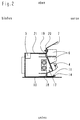
- Fig. 1 shows a receptacle 1, which has a substantially U-shaped cross section having.
- a leg 10 with an upwardly angled edge region 11 provided, this leg 10 over the module to be accommodated, e.g. one Transformer 2, protruding forward.
- This leg 10 is provided with holes 13 which for receiving fastening screws for connection to a not shown Serve frame.
- the angled edge region 11 of the leg 10 is provided with openings 12. These serve to receive projections 14, which are bent from an edge region 15 of a leg 16 of a striking plate 3 protrude.
- This striking plate 3 has a section 17 which is sawtooth-shaped in cross section whose outside terminals 4 are mounted for the electrical connection of the device.
- This sawtooth-shaped section 17 is arranged between two sections 18, 19 which both run essentially perpendicular to the leg 16 of the striking plate 3.
- the section 19 lies on an angled edge region 20 of the second leg 21 of the recording 1. To fasten the striking plate 3, this is in the area of Section 19 of the striking plate with holes 22 which are for receiving Serve screws 27 (FIG. 5), which in the angled edge region 20 of the receptacle 1 in a thread 26 are screwed.
- Serve screws 27 FIG. 5
- the striking plate 3 has bent tongues 6 above the terminals 4, which are for a separate routing of electrical lines with different voltage levels serve. Furthermore, the striking plate 3 has an angled away from the receptacle 1 7, which serves as drip protection for the terminals 4 and covers them.
- the leg 21 of the receptacle 1 is lateral Provide tabs 5.
- the web 9 of the receptacle 1 has an opening 24, which serves to accommodate a stepped section of module 2.
- the striking plate 3 with its section 18 and 19th presses against the module 2 and presses it against the web 9 of the receptacle 1. It works the sawtooth-shaped section 17 similar to a spring and allows an elastic Deformation of the striking plate 3.
Landscapes
- Engineering & Computer Science (AREA)
- Power Engineering (AREA)
- Mounting Components In General For Electric Apparatus (AREA)
Abstract
Description
Claims (4)
- Halterung für einen Modul (2), insbesondere einem Transformator, in einem einen Rahmen (8) aufweisenden Gerät, dadurch gekennzeichnet, daß die Halterung eine im wesentlichen U-förmige Aufnahme (1) aufweist, die an dem Rahmen (8) befestigt ist und deren einer Schenkel (10) aufgebogen ist und im aufgebogenen Bereich (11) mit Durchbrüchen (12) versehen ist, in die Vorsprünge (14) eines Schließblechs (3) eingreifen, die von einem abgekröpften Randbereich (15) eines abgewinkelten Schenkels (16) des Schließblechs (3) abstehen, wobei das Schließblech (3) mit der Aufnahme (1) lösbar verbunden ist und seitliche Laschen (5) zur seitlichen Abstützung des Moduls (2) vorgesehen sind.
- Halterung nach Anspruch 1, dadurch gekennzeichnet, daß der zweite Schenkel (21) der Aufnahme (1) einen vom ersten Schenkel (10) weggebogenen Randbereich (20) aufweist, an dem das Schließblech (3) anliegt und mittels Schrauben (27) befestigt ist.
- Halterung nach Anspruch 1 oder 2, dadurch gekennzeichnet, daß das Schließblech (3) einen im Querschnitt sägezahnförmigen Abschnitt (17) aufweist auf dem eine Klemme (4) befestigt ist.
- Halterung nach einem der Ansprüche 1 bis 3, dadurch gekennzeichnet, daß das Schließblech (3) oberhalb seines an dem abgewinkelten Bereich (20) des zweiten Schenkels (21) der Aufnahme (1) anliegenden Bereiches eine von der Aufnahme (1) weggerichtete Abwinkelung (7) aufweist, die die Klemme (4) überdeckt.
Applications Claiming Priority (2)
| Application Number | Priority Date | Filing Date | Title |
|---|---|---|---|
| AT53099 | 1999-03-23 | ||
| AT0053099A AT408402B (de) | 1999-03-23 | 1999-03-23 | Transformatorhalterung |
Publications (2)
| Publication Number | Publication Date |
|---|---|
| EP1039603A1 true EP1039603A1 (de) | 2000-09-27 |
| EP1039603B1 EP1039603B1 (de) | 2011-04-27 |
Family
ID=3493073
Family Applications (1)
| Application Number | Title | Priority Date | Filing Date |
|---|---|---|---|
| EP00105902A Expired - Lifetime EP1039603B1 (de) | 1999-03-23 | 2000-03-22 | Halterung für einen Modul |
Country Status (3)
| Country | Link |
|---|---|
| EP (1) | EP1039603B1 (de) |
| AT (2) | AT408402B (de) |
| DE (2) | DE10014100A1 (de) |
Families Citing this family (3)
| Publication number | Priority date | Publication date | Assignee | Title |
|---|---|---|---|---|
| DE202004004629U1 (de) * | 2004-03-25 | 2004-07-29 | Actaris Zähler & Systemtechnik GmbH | Vorrichtung zur Montage eines Gehäuses |
| DE202017103771U1 (de) * | 2017-06-23 | 2018-06-27 | Dortmunder Energie- und Wasserversorgung GmbH | Hausanschlusskasten-Montageelement für einen Hausanschlusskasten für die elektrische Energieversorgung |
| AT18061U1 (de) * | 2020-10-27 | 2023-12-15 | Fami Srl | Modulare einhakvorrichtung für einzel- oder mehrfachelektrokästen |
Citations (1)
| Publication number | Priority date | Publication date | Assignee | Title |
|---|---|---|---|---|
| US3758828A (en) * | 1972-02-29 | 1973-09-11 | Gen Electric | Relay center for remote control wiring system |
Family Cites Families (5)
| Publication number | Priority date | Publication date | Assignee | Title |
|---|---|---|---|---|
| US3601661A (en) * | 1970-02-02 | 1971-08-24 | Westinghouse Air Brake Co | Finned modular electrical equipment package with mounting bracket |
| US4296545A (en) * | 1980-03-31 | 1981-10-27 | Oy Helvar | Casing hook used to impregnate choke or transformer |
| FR2668971A1 (fr) * | 1990-11-14 | 1992-05-15 | Merlin Gerin | Boitier de protection d'un automate industriel. |
| DE4440455C2 (de) * | 1994-11-03 | 1996-09-12 | Krone Ag | Montagevorrichtung für RJ-Verbindungselemente der Nachrichten- und Datentechnik (Patch-Panel) |
| DE19544834C1 (de) * | 1995-12-01 | 1997-02-27 | Schroff Gmbh | Befestigungsvorrichtung |
-
1999
- 1999-03-23 AT AT0053099A patent/AT408402B/de not_active IP Right Cessation
-
2000
- 2000-03-22 DE DE10014100A patent/DE10014100A1/de not_active Withdrawn
- 2000-03-22 AT AT00105902T patent/ATE507600T1/de active
- 2000-03-22 EP EP00105902A patent/EP1039603B1/de not_active Expired - Lifetime
- 2000-03-22 DE DE50016099T patent/DE50016099D1/de not_active Expired - Lifetime
Patent Citations (1)
| Publication number | Priority date | Publication date | Assignee | Title |
|---|---|---|---|---|
| US3758828A (en) * | 1972-02-29 | 1973-09-11 | Gen Electric | Relay center for remote control wiring system |
Also Published As
| Publication number | Publication date |
|---|---|
| ATA53099A (de) | 2001-03-15 |
| DE50016099D1 (de) | 2011-06-09 |
| AT408402B (de) | 2001-11-26 |
| ATE507600T1 (de) | 2011-05-15 |
| EP1039603B1 (de) | 2011-04-27 |
| DE10014100A1 (de) | 2000-10-12 |
Similar Documents
| Publication | Publication Date | Title |
|---|---|---|
| EP0399091B1 (de) | Vorrichtung zum elektrisch leitenden Verbinden einer Leiterplatte mit einer Modulschiene eines Baugruppenträgers | |
| DE2104050C3 (de) | Klemmhalterung | |
| EP0080612A2 (de) | Querverbinder | |
| EP0776077B1 (de) | Vorrichtung zum Befestigen von Zusatzeinrichtungen an Hutschienen | |
| DE10300723B4 (de) | Sammelschienensystem und Anschluss- oder Geräte-Adapter | |
| EP0926791B1 (de) | Adapter mit Adaptergehäuse und daran befestigbarem Gerätehalter für elektrische Installationsgeräte | |
| WO1998023001A1 (de) | Montageschiene für einen schaltschrank | |
| AT408402B (de) | Transformatorhalterung | |
| DE10306813B4 (de) | Kochfeld | |
| DE102008035722A1 (de) | Elektrisches/elektronisches Installationsgerät | |
| DE19721776C2 (de) | Tragteil für eine Kochfläche | |
| DE19949508A1 (de) | Vorrichtung zur Befestigung von Schirmklemmen | |
| DE9310630U1 (de) | An einer Montagefläche befestigtes elektrisches Gerät | |
| DE29723416U1 (de) | Tragteil für eine Kochfläche | |
| DE2734033C3 (de) | Befestigungsanordnung des Meßwerkes eines Elektrizitätszählers | |
| DE102016100979B3 (de) | Elektrischer Wippenschalter | |
| DE2364812C2 (de) | Anordnung eines Bürstenträgers und eines Spannungsreglers an einer elektrischen Maschine | |
| CH657480A5 (de) | Vorrichtung zum festklemmen elektrischer leiter, insbesondere von draehten. | |
| DE19708715C1 (de) | Kabelkanal für Schaltschränke und Schaltanlagen | |
| DE19537531C1 (de) | Anschlußvorrichtung für die Telekommunikations- und Datentechnik | |
| DE102017205061A1 (de) | Kochfeld | |
| DE69111684T2 (de) | Isolierendes Gehäuse für Miniatur-Lastschalter mit Vorassemblagemitteln. | |
| DE202023001900U1 (de) | Haltebügel für eine Spanneinrichtung zum Befestigen einer Gitteranordnung am Rahmenprofil eines Solarmoduls | |
| DE29802469U1 (de) | Verbindung von Installationsgeräten mittels einer Platte am Tragring | |
| CH575079A5 (en) | Clamp for two profiled rails in electrical terminal box - has U-shaped sheet metal strip with hole in crosspiece for coupling bolt |
Legal Events
| Date | Code | Title | Description |
|---|---|---|---|
| PUAI | Public reference made under article 153(3) epc to a published international application that has entered the european phase |
Free format text: ORIGINAL CODE: 0009012 |
|
| AK | Designated contracting states |
Kind code of ref document: A1 Designated state(s): AT BE CH CY DE DK ES FI FR GB GR IE IT LI LU MC NL PT SE |
|
| AX | Request for extension of the european patent |
Free format text: AL;LT;LV;MK;RO;SI |
|
| 17P | Request for examination filed |
Effective date: 20010327 |
|
| AKX | Designation fees paid |
Free format text: AT BE CH CY DE DK ES FI FR GB GR IE IT LI LU MC NL PT SE |
|
| RAP1 | Party data changed (applicant data changed or rights of an application transferred) |
Owner name: VAILLANT GMBH |
|
| 17Q | First examination report despatched |
Effective date: 20060717 |
|
| GRAP | Despatch of communication of intention to grant a patent |
Free format text: ORIGINAL CODE: EPIDOSNIGR1 |
|
| GRAS | Grant fee paid |
Free format text: ORIGINAL CODE: EPIDOSNIGR3 |
|
| GRAA | (expected) grant |
Free format text: ORIGINAL CODE: 0009210 |
|
| AK | Designated contracting states |
Kind code of ref document: B1 Designated state(s): AT BE CH CY DE DK ES FI FR GB GR IE IT LI LU MC NL PT SE |
|
| REG | Reference to a national code |
Ref country code: GB Ref legal event code: FG4D Free format text: NOT ENGLISH |
|
| REG | Reference to a national code |
Ref country code: CH Ref legal event code: EP |
|
| REG | Reference to a national code |
Ref country code: IE Ref legal event code: FG4D Free format text: LANGUAGE OF EP DOCUMENT: GERMAN |
|
| REF | Corresponds to: |
Ref document number: 50016099 Country of ref document: DE Date of ref document: 20110609 Kind code of ref document: P |
|
| REG | Reference to a national code |
Ref country code: DE Ref legal event code: R096 Ref document number: 50016099 Country of ref document: DE Effective date: 20110609 |
|
| REG | Reference to a national code |
Ref country code: NL Ref legal event code: VDEP Effective date: 20110427 |
|
| PG25 | Lapsed in a contracting state [announced via postgrant information from national office to epo] |
Ref country code: SE Free format text: LAPSE BECAUSE OF FAILURE TO SUBMIT A TRANSLATION OF THE DESCRIPTION OR TO PAY THE FEE WITHIN THE PRESCRIBED TIME-LIMIT Effective date: 20110427 Ref country code: PT Free format text: LAPSE BECAUSE OF FAILURE TO SUBMIT A TRANSLATION OF THE DESCRIPTION OR TO PAY THE FEE WITHIN THE PRESCRIBED TIME-LIMIT Effective date: 20110829 |
|
| REG | Reference to a national code |
Ref country code: IE Ref legal event code: FD4D |
|
| PG25 | Lapsed in a contracting state [announced via postgrant information from national office to epo] |
Ref country code: ES Free format text: LAPSE BECAUSE OF FAILURE TO SUBMIT A TRANSLATION OF THE DESCRIPTION OR TO PAY THE FEE WITHIN THE PRESCRIBED TIME-LIMIT Effective date: 20110807 Ref country code: GR Free format text: LAPSE BECAUSE OF FAILURE TO SUBMIT A TRANSLATION OF THE DESCRIPTION OR TO PAY THE FEE WITHIN THE PRESCRIBED TIME-LIMIT Effective date: 20110728 Ref country code: CY Free format text: LAPSE BECAUSE OF FAILURE TO SUBMIT A TRANSLATION OF THE DESCRIPTION OR TO PAY THE FEE WITHIN THE PRESCRIBED TIME-LIMIT Effective date: 20110427 Ref country code: FI Free format text: LAPSE BECAUSE OF FAILURE TO SUBMIT A TRANSLATION OF THE DESCRIPTION OR TO PAY THE FEE WITHIN THE PRESCRIBED TIME-LIMIT Effective date: 20110427 |
|
| PG25 | Lapsed in a contracting state [announced via postgrant information from national office to epo] |
Ref country code: NL Free format text: LAPSE BECAUSE OF FAILURE TO SUBMIT A TRANSLATION OF THE DESCRIPTION OR TO PAY THE FEE WITHIN THE PRESCRIBED TIME-LIMIT Effective date: 20110427 |
|
| PG25 | Lapsed in a contracting state [announced via postgrant information from national office to epo] |
Ref country code: IE Free format text: LAPSE BECAUSE OF FAILURE TO SUBMIT A TRANSLATION OF THE DESCRIPTION OR TO PAY THE FEE WITHIN THE PRESCRIBED TIME-LIMIT Effective date: 20110427 |
|
| PG25 | Lapsed in a contracting state [announced via postgrant information from national office to epo] |
Ref country code: DK Free format text: LAPSE BECAUSE OF FAILURE TO SUBMIT A TRANSLATION OF THE DESCRIPTION OR TO PAY THE FEE WITHIN THE PRESCRIBED TIME-LIMIT Effective date: 20110427 |
|
| PLBE | No opposition filed within time limit |
Free format text: ORIGINAL CODE: 0009261 |
|
| STAA | Information on the status of an ep patent application or granted ep patent |
Free format text: STATUS: NO OPPOSITION FILED WITHIN TIME LIMIT |
|
| 26N | No opposition filed |
Effective date: 20120130 |
|
| REG | Reference to a national code |
Ref country code: DE Ref legal event code: R097 Ref document number: 50016099 Country of ref document: DE Effective date: 20120130 |
|
| PG25 | Lapsed in a contracting state [announced via postgrant information from national office to epo] |
Ref country code: IT Free format text: LAPSE BECAUSE OF FAILURE TO SUBMIT A TRANSLATION OF THE DESCRIPTION OR TO PAY THE FEE WITHIN THE PRESCRIBED TIME-LIMIT Effective date: 20110427 |
|
| BERE | Be: lapsed |
Owner name: VAILLANT G.M.B.H. Effective date: 20120331 |
|
| PG25 | Lapsed in a contracting state [announced via postgrant information from national office to epo] |
Ref country code: MC Free format text: LAPSE BECAUSE OF NON-PAYMENT OF DUE FEES Effective date: 20120331 |
|
| REG | Reference to a national code |
Ref country code: CH Ref legal event code: PL |
|
| GBPC | Gb: european patent ceased through non-payment of renewal fee |
Effective date: 20120322 |
|
| REG | Reference to a national code |
Ref country code: FR Ref legal event code: ST Effective date: 20121130 |
|
| PG25 | Lapsed in a contracting state [announced via postgrant information from national office to epo] |
Ref country code: LI Free format text: LAPSE BECAUSE OF NON-PAYMENT OF DUE FEES Effective date: 20120331 Ref country code: CH Free format text: LAPSE BECAUSE OF NON-PAYMENT OF DUE FEES Effective date: 20120331 Ref country code: BE Free format text: LAPSE BECAUSE OF NON-PAYMENT OF DUE FEES Effective date: 20120331 Ref country code: GB Free format text: LAPSE BECAUSE OF NON-PAYMENT OF DUE FEES Effective date: 20120322 Ref country code: FR Free format text: LAPSE BECAUSE OF NON-PAYMENT OF DUE FEES Effective date: 20120402 |
|
| REG | Reference to a national code |
Ref country code: AT Ref legal event code: MM01 Ref document number: 507600 Country of ref document: AT Kind code of ref document: T Effective date: 20120322 |
|
| PG25 | Lapsed in a contracting state [announced via postgrant information from national office to epo] |
Ref country code: AT Free format text: LAPSE BECAUSE OF NON-PAYMENT OF DUE FEES Effective date: 20120322 |
|
| PG25 | Lapsed in a contracting state [announced via postgrant information from national office to epo] |
Ref country code: LU Free format text: LAPSE BECAUSE OF NON-PAYMENT OF DUE FEES Effective date: 20120322 |
|
| PGFP | Annual fee paid to national office [announced via postgrant information from national office to epo] |
Ref country code: DE Payment date: 20160302 Year of fee payment: 17 |
|
| REG | Reference to a national code |
Ref country code: DE Ref legal event code: R119 Ref document number: 50016099 Country of ref document: DE |
|
| PG25 | Lapsed in a contracting state [announced via postgrant information from national office to epo] |
Ref country code: DE Free format text: LAPSE BECAUSE OF NON-PAYMENT OF DUE FEES Effective date: 20171003 |