EP1039491A2 - Kühlvorrichtung für eine Kondensatorbatterie - Google Patents
Kühlvorrichtung für eine Kondensatorbatterie Download PDFInfo
- Publication number
- EP1039491A2 EP1039491A2 EP00105437A EP00105437A EP1039491A2 EP 1039491 A2 EP1039491 A2 EP 1039491A2 EP 00105437 A EP00105437 A EP 00105437A EP 00105437 A EP00105437 A EP 00105437A EP 1039491 A2 EP1039491 A2 EP 1039491A2
- Authority
- EP
- European Patent Office
- Prior art keywords
- capacitor
- capacitors
- busbar
- capacitor bank
- cooling device
- Prior art date
- Legal status (The legal status is an assumption and is not a legal conclusion. Google has not performed a legal analysis and makes no representation as to the accuracy of the status listed.)
- Withdrawn
Links
Images

Classifications
-
- H—ELECTRICITY
- H01—ELECTRIC ELEMENTS
- H01G—CAPACITORS; CAPACITORS, RECTIFIERS, DETECTORS, SWITCHING DEVICES, LIGHT-SENSITIVE OR TEMPERATURE-SENSITIVE DEVICES OF THE ELECTROLYTIC TYPE
- H01G2/00—Details of capacitors not covered by a single one of groups H01G4/00-H01G11/00
- H01G2/08—Cooling arrangements; Heating arrangements; Ventilating arrangements
-
- H—ELECTRICITY
- H01—ELECTRIC ELEMENTS
- H01G—CAPACITORS; CAPACITORS, RECTIFIERS, DETECTORS, SWITCHING DEVICES, LIGHT-SENSITIVE OR TEMPERATURE-SENSITIVE DEVICES OF THE ELECTROLYTIC TYPE
- H01G11/00—Hybrid capacitors, i.e. capacitors having different positive and negative electrodes; Electric double-layer [EDL] capacitors; Processes for the manufacture thereof or of parts thereof
- H01G11/78—Cases; Housings; Encapsulations; Mountings
- H01G11/82—Fixing or assembling a capacitive element in a housing, e.g. mounting electrodes, current collectors or terminals in containers or encapsulations
-
- Y—GENERAL TAGGING OF NEW TECHNOLOGICAL DEVELOPMENTS; GENERAL TAGGING OF CROSS-SECTIONAL TECHNOLOGIES SPANNING OVER SEVERAL SECTIONS OF THE IPC; TECHNICAL SUBJECTS COVERED BY FORMER USPC CROSS-REFERENCE ART COLLECTIONS [XRACs] AND DIGESTS
- Y02—TECHNOLOGIES OR APPLICATIONS FOR MITIGATION OR ADAPTATION AGAINST CLIMATE CHANGE
- Y02E—REDUCTION OF GREENHOUSE GAS [GHG] EMISSIONS, RELATED TO ENERGY GENERATION, TRANSMISSION OR DISTRIBUTION
- Y02E60/00—Enabling technologies; Technologies with a potential or indirect contribution to GHG emissions mitigation
- Y02E60/10—Energy storage using batteries
Definitions
- the invention relates to the field of cooling technology.
- the invention relates a cooling device for a capacitor bank.
- capacitors of a capacitor bank for power electronics applications in the traction area require a cooling system to dissipate the heat loss occurring in the capacitors.
- capacitor batteries are then cooled by a fan, which generates an air flow.
- air cooling requires special measures for air treatment and maintenance. For the power density present in the traction area, a common air cooling of the capacitors of a capacitor bank is therefore not sufficient to dissipate the heat loss, so that coolers with liquid cooling media are used.
- a generic cooling device is described in US 5,812,365.
- a capacitor bank is disclosed therein, in which the same electrode poles of the capacitors used are each connected to a busbar with screws and thus form a parallel connection of the capacitors.
- the busbar lines are arranged in parallel and each run through a cooling channel in which a liquid cooling medium circulates, which transports the heat away. Due to the use of the cooling device according to US Pat. No. 5,812,365 up to a frequency of 400 kHz, a low-induction structure in the form shown is necessary, in which the width which the two busbar strands form extends far beyond the width of the entire capacitors used in the capacitor bank. However, a small size is required for the capacitor banks to be used in the traction area, in particular for the cooling device of the capacitor bank. The cooling device disclosed in US Pat. No. 5,812,365 is therefore not suitable for use in the traction area with the required small installation sizes.
- traction applications include not only the condenser batteries to be cooled other components, such as power electronic semiconductor switches used Power converters that also need to be cooled. Because of the very limited Space constraints require that as little as possible be separate from each other independent cooling circuits are operated, since otherwise complex pump systems must be made available several times with the associated infrastructure.
- the cooling device according to the invention for a capacitor bank comprises one each Rail system, which has a cooling channel in which a coolant circulates, and the similarly polarized capacitor electrodes used capacitors of the capacitor bank electrically connected to each other to form a parallel connection.
- the Busbar trunking in the case of on a single capacitor area of each capacitor arranged capacitor electrodes have a much smaller width, as a width of the capacitor bank defined by the capacitors perpendicular to a longitudinal axis.
- the respective busbar strand advantageously a smaller width than that through the capacitors perpendicular to the longitudinal axis specified width of the capacitor bank.
- this makes a very space-saving design of the cooling device for a capacitor bank achieved, like this is required for traction applications.
- the cost of materials, the weight and the resulting costs due to the construction of the cooling device according to the invention be kept low.
- the cooling device can take over the function of a coolant distribution, by having at least three coolant connections, two of which Coolant connections are coolant distribution connections. This makes it very easy to the cooling device to an existing cooling system, for example for power electronics Semiconductor switch of a converter used to connect, so that an additional independent cooling system can be dispensed with. From the cooling device can then very advantageously be further cooled by means of the coolant distribution connections Elements are supplied.
- FIG. 1 a shows an exemplary embodiment of the cooling device for a capacitor bank according to the invention in a front view.
- the capacitor bank comprises at least two capacitors 6, each capacitor 6 having two capacitor electrodes 1 and these being arranged on a single capacitor surface 8 according to FIG. 1 a.
- the capacitors 6 are arranged according to FIG. 1b, which shows a top view of the exemplary embodiment according to FIG. 1a, in the direction of a longitudinal axis XX.
- the capacitor electrodes 1 are designed such that a splinting can be attached to them by means of detachable fastening means 2.
- the capacitors 6 are electrically conductively connected at their similarly polarized capacitor electrodes 1, that is, at their plus poles and at their minus poles of the capacitors 6, with the aid of a busbar 7 to form a parallel connection.
- Each of the two busbar strands 7 has a cooling channel 3 in which a coolant circulates.
- the busbar strands 7 according to the invention in FIG. 1b are designed for capacitors 6 with capacitor electrodes 1 arranged on a single capacitor surface 8 in such a way that together they have a substantially smaller width B K than a width B B defined by the capacitors 6 perpendicular to the longitudinal axis XX Capacitor bank.
- This embodiment of the cooling device has the advantage that it has an extremely space-saving design, as is required in particular for use in the traction area. In addition, only a small amount of material is required for the construction, which results in an additional advantage of a very low weight.
- a further advantage of this exemplary embodiment of the cooling device can be seen that the busbar branches assume a supporting function for the entire capacitor bank, so that stabilizing means between the capacitors can be dispensed with.
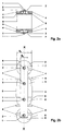
- FIG. 2a shows the embodiment according to FIG. 2a in a top view.
- the capacitor bank comprises capacitors 6, which are arranged in the direction of the longitudinal axis XX.
- the capacitor electrodes 1 of each capacitor 6 are arranged on different capacitor surfaces 8.
- the capacitor electrodes 1 of the same polarity are electrically conductively connected to one another via respective busbar strands 7 to form a parallel connection. It has an advantage in the embodiment of the cooling device shown in FIGS.
- Busbar strands 7 cause a further improvement in the stability of the entire capacitor bank.
- additional, mechanically stabilizing components can be dispensed with entirely.
- the busbar strands 7 according to the invention in FIG. 2b are designed for capacitors 6 with capacitor electrodes 1 arranged on different capacitor surfaces 8 such that each individual busbar trunk 7 has a substantially smaller width B S than a width B B defined by the capacitors 6 perpendicular to the longitudinal axis XX the capacitor bank.
- the busbar branch comprises further 7 at least three coolant connections 4, at least two of which coolant distribution connections are.
- the coolant connections 4 are designed such that common coolant hoses and / or coolant lines can be connected. Resulting from it There are advantages in that the cooling device is already connected to one in a particularly simple manner Existing cooling system can be connected, such as in traction applications for power electronic semiconductor switches of a converter used therein. Thus, an additional independent cooling system with the necessary complex can be used Infrastructure such as pumps, expansion tanks, etc. can be dispensed with.
- the Cooling device according to the invention by means of the coolant distribution connections Coolant connections 4 take over a function of the distribution of the coolant and thus supply additional elements to be cooled. This allows a complex coolant distribution device save on.
Landscapes
- Engineering & Computer Science (AREA)
- Power Engineering (AREA)
- Microelectronics & Electronic Packaging (AREA)
- Secondary Cells (AREA)
- Cooling Or The Like Of Electrical Apparatus (AREA)
- Electric Double-Layer Capacitors Or The Like (AREA)
Abstract
Description
Bedingt durch den Einsatz der Kühlvorrichtung nach US 5,812,365 bis zu einer Frequenz von 400 kHz ist ein induktionsarmer Aufbau in der gezeigten Form notwendig, bei der die Breite, die die beiden Verschienungsstränge bilden, weit über die Breite der gesamten in der Kondensatorbank eingesetzten Kondensatoren hinausgehen. Für die im Traktionsbereich einzusetzenden Kondensatorbatterien ist jedoch eine geringe Baugrösse gefordert, insbesondere für die Kühlvorrichtung der Kondensatorbatterie. Die in der US 5,812,365 offenbarte Kühlvorrichtung ist deshalb für den Einsatz im Traktionsbereich mit den geforderten kleinen Einbaugrössen nicht geeignet.
- Fig. 1a
- eine Vorderansicht eines Ausführungsbeispiels einer Kühlvorrichtung für eine Kondensatorbatterie mit auf einer einzigen Kondensatorfläche angeordneten Kondensatorelektroden,
- Fig. 1b
- eine Darstellung des Ausführungsbeispiels der Kühlvorrichtung nach Fig. 1a in der Draufsicht,
- Fig. 2a
- eine Vorderansicht eines weiteren Ausführungsbeispiels einer Kühlvorrichtung in für eine Kondensatorbatterie für Kondensatoren mit auf verschiedenen Kondensatorflächen angeordneten Kondensatorelektroden,
- Fig. 2b
- eine Darstellung des Ausführungsbeispiels der Kühlvorrichtung nach Fig.2a in der Draufsicht.
Die erfindungsgemässen Verschienungsstränge 7 in Fig. 1b sind für Kondensatoren 6 mit auf einer einzigen Kondensatorfläche 8 angeordneten Kondensatorelektroden 1 so ausgeführt, dass sie zusammen eine wesentlich geringere Breite BK haben, als eine durch die Kondensatoren 6 senkrecht zur Längsachse X-X festgelegte Breite BB der Kondensatorbatterie. Diese Ausführungsform der Kühlvorrichtung hat den Vorteil, dass sie extrem platzsparend aufgebaut ist, wie dies insbesondere für den Einsatz im Traktionsbereich erforderlich ist. Darüberhinaus ist für den Aufbau ein nur geringer Materialaufwand notwendig, woraus als zusätzlicher Vorteil ein sehr geringes Gewicht resultiert. Als weiterer Vorteil dieses Ausführungsbeispiels der Kühlvorrichtung ist zu sehen, dass die Verschienungsstränge eine tragende Funktion der gesamten Kondensatorbatterie übernehmen, so dass auf stabilisiernde Mittel zwischen den Kondensatoren verzichtet werden kann.
Die erfindungsgemässen Verschienungsstränge 7 in Fig. 2b sind für Kondensatoren 6 mit auf verschiedenen Kondensatorflächen 8 angeordneten Kondensatorelektroden 1 so ausgeführt, dass jeder einzelne Verschienungsstrang 7 eine wesentlich geringere Breite BS hat, als eine durch die Kondensatoren 6 senkrecht zur Längsachse X-X festgelegte Breite BB der Kondensatorbatterie. Die bereits für das Ausführungsbeispiel gemäss Fig. 1a und Fig. 1b genannten Vorteile des platzsparenden Aufbaus und die daraus resultierende Ersparnis bezogen auf Material und Gewicht gilt auch für das Ausführungsbeispiel gemäss Fig. 2a und Fig. 2b.
- 1
- Kondensatorelektrode
- 2
- lösbare Befestigungsmittel
- 3
- Kühlkanal
- 4
- Kühlmittelanschluss
- 5
- elektrischer Anschluss
- 6
- Kondensator
- 7
- Verschienungsstrang
- 8
- Kondensatorfläche
Claims (3)
- Kühlvorrichtung für eine Kondensatorbatterie, wobei die Kondensatorbatterie mindestens zwei Kondensatoren (6) mit jeweils zwei auf einer einzigen Kondensatorfläche (8) angeordneten Kondensatorelektroden (1) aufweist und die Kondensatoren (6) in Richtung einer Längsachse (X-X) angeordnet sind und über jeweils einen Verschienungsstrang (7), der einen Kühlkanal (3) umfasst und in dem ein Kühlmittel zirkuliert, an ihren gleichartig gepolten Kondensatorelektroden (1) mittels lösbarer Befestigungsmittel (2) zu einer Parallelschaltung elektrisch leitend verbunden sind, wobei die Verschienungsstränge (7) zusammen eine wesentlich geringere Breite BK aufweisen, als eine durch die Kondensatoren (6) senkrecht zur Längsachse (X-X) festgelegte Breite BB der Kondensatorbatterie.
- Kühlvorrichtung für eine Kondensatorbatterie, wobei die Kondensatorbatterie mindestens zwei Kondensatoren (6) mit jeweils zwei auf verschiedenen Kondensatorflächen (8) angeordneten Kondensatorelektroden (1) aufweist und die Kondensatoren (6) in Richtung einer Längsachse (X-X) angeordnet sind und über jeweils einen Verschienungsstrang (7), der einen Kühlkanal (3) umfasst und in dem ein Kühlmittel zirkuliert, an ihren gleichartig gepolten Kondensatorelektroden (1) mittels lösbarer Befestigungsmittel (2) zu einer Parallelschaltung elektrisch leitend verbunden sind, wobei jeder einzelne Verschienungsstrang (7) eine wesentlich geringere Breite BS aufweist, als eine durch die Kondensatoren (6) senkrecht zur Längsachse (X-X) festgelegte Breite BB der Kondensatorbatterie.
- Kühlvorrichtung nach Anspruch 1 oder 2, dadurch gekennzeichnet, dass der Verschienungsstrang (7) mindestens drei Kühlmittelanschlüsse (4) aufweist, wobei mindestens zwei davon Kühlmittelverteilanschlüsse sind.
Applications Claiming Priority (2)
| Application Number | Priority Date | Filing Date | Title |
|---|---|---|---|
| DE19912394A DE19912394A1 (de) | 1999-03-19 | 1999-03-19 | Kühlvorrichtung für eine Kondensatorbatterie |
| DE19912394 | 1999-03-19 |
Publications (2)
| Publication Number | Publication Date |
|---|---|
| EP1039491A2 true EP1039491A2 (de) | 2000-09-27 |
| EP1039491A3 EP1039491A3 (de) | 2004-02-11 |
Family
ID=7901635
Family Applications (1)
| Application Number | Title | Priority Date | Filing Date |
|---|---|---|---|
| EP00105437A Withdrawn EP1039491A3 (de) | 1999-03-19 | 2000-03-15 | Kühlvorrichtung für eine Kondensatorbatterie |
Country Status (2)
| Country | Link |
|---|---|
| EP (1) | EP1039491A3 (de) |
| DE (1) | DE19912394A1 (de) |
Cited By (1)
| Publication number | Priority date | Publication date | Assignee | Title |
|---|---|---|---|---|
| EP4749803A1 (de) * | 2024-11-21 | 2026-05-27 | Skeleton Technologies GmbH | Elektrisches system mit stromschienen als kühlelemente |
Families Citing this family (1)
| Publication number | Priority date | Publication date | Assignee | Title |
|---|---|---|---|---|
| DE102004052287A1 (de) * | 2004-10-27 | 2006-05-04 | Robert Bosch Gmbh | Elektrische Schaltungseinheit |
Family Cites Families (3)
| Publication number | Priority date | Publication date | Assignee | Title |
|---|---|---|---|---|
| DE1132659B (de) * | 1959-07-31 | 1962-07-05 | Siemens Ag | Anordnung zur Kuehlung von in geschlossenen Gehaeusen angeordneten Starkstromkonden-satoren |
| FR2716033B1 (fr) * | 1994-02-09 | 1996-04-05 | Jakoubovitch A | Dispositif d'assemblage de condensateurs de puissance. |
| DE4412990A1 (de) * | 1994-04-15 | 1995-10-19 | Abb Patent Gmbh | Stromrichteranlage mit flüssigkeits- oder luftgekühlten Leistungshalbleitern und Gleichspannungszwischenkreis |
-
1999
- 1999-03-19 DE DE19912394A patent/DE19912394A1/de not_active Withdrawn
-
2000
- 2000-03-15 EP EP00105437A patent/EP1039491A3/de not_active Withdrawn
Cited By (1)
| Publication number | Priority date | Publication date | Assignee | Title |
|---|---|---|---|---|
| EP4749803A1 (de) * | 2024-11-21 | 2026-05-27 | Skeleton Technologies GmbH | Elektrisches system mit stromschienen als kühlelemente |
Also Published As
| Publication number | Publication date |
|---|---|
| EP1039491A3 (de) | 2004-02-11 |
| DE19912394A1 (de) | 2000-09-21 |
Similar Documents
| Publication | Publication Date | Title |
|---|---|---|
| EP0142678A2 (de) | Halbleiterventil | |
| EP1469711A2 (de) | Gehäuse mit Kühlung für elektronische Steuergeräte, insbesondere in Kfz | |
| DE20200484U1 (de) | Kühlvorrichtung für Bauteile, insbesondere für elektrische oder elektronische Bauteile, wie Stromrichter o.dgl. | |
| EP2847445A1 (de) | Anordnung eines ladeluftkühlers in einem ansaugrohr | |
| DE202012012767U1 (de) | Leistungshalbleitermodulsystem | |
| DE4014918A1 (de) | Elektromotor | |
| DE102017206113A1 (de) | Wärmeübertrager für ein Kraftfahrzeug | |
| DE102010063155A1 (de) | Befestigungsvorrichtung für ein Gehäuse eines Steuergerätes | |
| DE202015101776U1 (de) | Rangierwabe | |
| EP1249868A1 (de) | Kühlungseinrichtung für ein elektronisches Bauelement sowie Kühlsystem mit solchen Kühlungseinrichtungen | |
| EP2201632B1 (de) | Hochtemperatur-polymer-elektrolyt-membran-brennstoffzelle (ht-pemfc) einschliesslich vorrichtungen zu deren kühlung | |
| DE1913546A1 (de) | Baugruppe mit mindestens zwei,durch einen Spannbolzen zusammengehaltenen Kuehlkoerpern | |
| DE102009054785A1 (de) | Bremschopper | |
| DE19912394A1 (de) | Kühlvorrichtung für eine Kondensatorbatterie | |
| DE3507255A1 (de) | Gehaeuse fuer elektrische bauteile | |
| DE19758058B4 (de) | Regalsystem | |
| DE102023114517A1 (de) | Elektronikbausatz mit mehreren symmetrisch gekühlten Kondensatoren | |
| DE102022203362A1 (de) | Motorintegrierter Wechselrichter | |
| DE19843110A1 (de) | Stromrichterschaltung mit variabler Konfiguration für Traktionsanwendungen | |
| EP4268552B1 (de) | Kühlvorrichtung zur kühlung eines halbleitermoduls und umrichter mit der kühlvorrichtung | |
| DE102017222114B4 (de) | AC Stromschiene für einen Wechselrichter | |
| DE102020207713A1 (de) | Kühlgeometrie für Leistungselektroniken | |
| DE20218394U1 (de) | Ventilbauelement-Satz in Zweigpaar-Konfiguration für einen elektrischen Wechselrichter | |
| DE202015104615U1 (de) | Leistungswandlermodul | |
| DE202019104966U1 (de) | Kühlkörper |
Legal Events
| Date | Code | Title | Description |
|---|---|---|---|
| PUAI | Public reference made under article 153(3) epc to a published international application that has entered the european phase |
Free format text: ORIGINAL CODE: 0009012 |
|
| AK | Designated contracting states |
Kind code of ref document: A2 Designated state(s): AT BE CH CY DE DK ES FI FR GB GR IE IT LI LU MC NL PT SE |
|
| AX | Request for extension of the european patent |
Free format text: AL;LT;LV;MK;RO;SI |
|
| RAP1 | Party data changed (applicant data changed or rights of an application transferred) |
Owner name: DAIMLERCHRYSLER RAIL SYSTEMS GMBH |
|
| PUAL | Search report despatched |
Free format text: ORIGINAL CODE: 0009013 |
|
| AK | Designated contracting states |
Kind code of ref document: A3 Designated state(s): AT BE CH CY DE DK ES FI FR GB GR IE IT LI LU MC NL PT SE |
|
| AX | Request for extension of the european patent |
Extension state: AL LT LV MK RO SI |
|
| 17P | Request for examination filed |
Effective date: 20040323 |
|
| RAP1 | Party data changed (applicant data changed or rights of an application transferred) |
Owner name: BOMBARDIER TRANSPORTATION GMBH |
|
| AKX | Designation fees paid |
Designated state(s): AT BE CH CY DE DK ES FI FR GB GR IE IT LI LU MC NL PT SE |
|
| STAA | Information on the status of an ep patent application or granted ep patent |
Free format text: STATUS: THE APPLICATION IS DEEMED TO BE WITHDRAWN |
|
| 18D | Application deemed to be withdrawn |
Effective date: 20041001 |