EP1038713A2 - Fahrzeug mit einem Antriebsstrang für wenigstens zwei Antriebsräder und mit einem Brennkraftmaschinen-Antrieb sowie mit einem Brennstoffzellensystem - Google Patents
Fahrzeug mit einem Antriebsstrang für wenigstens zwei Antriebsräder und mit einem Brennkraftmaschinen-Antrieb sowie mit einem Brennstoffzellensystem Download PDFInfo
- Publication number
- EP1038713A2 EP1038713A2 EP00101306A EP00101306A EP1038713A2 EP 1038713 A2 EP1038713 A2 EP 1038713A2 EP 00101306 A EP00101306 A EP 00101306A EP 00101306 A EP00101306 A EP 00101306A EP 1038713 A2 EP1038713 A2 EP 1038713A2
- Authority
- EP
- European Patent Office
- Prior art keywords
- fuel cell
- drive
- internal combustion
- combustion engine
- cell system
- Prior art date
- Legal status (The legal status is an assumption and is not a legal conclusion. Google has not performed a legal analysis and makes no representation as to the accuracy of the status listed.)
- Granted
Links
Images


Classifications
-
- B—PERFORMING OPERATIONS; TRANSPORTING
- B60—VEHICLES IN GENERAL
- B60K—ARRANGEMENT OR MOUNTING OF PROPULSION UNITS OR OF TRANSMISSIONS IN VEHICLES; ARRANGEMENT OR MOUNTING OF PLURAL DIVERSE PRIME-MOVERS IN VEHICLES; AUXILIARY DRIVES FOR VEHICLES; INSTRUMENTATION OR DASHBOARDS FOR VEHICLES; ARRANGEMENTS IN CONNECTION WITH COOLING, AIR INTAKE, GAS EXHAUST OR FUEL SUPPLY OF PROPULSION UNITS IN VEHICLES
- B60K6/00—Arrangement or mounting of plural diverse prime-movers for mutual or common propulsion, e.g. hybrid propulsion systems comprising electric motors and internal combustion engines
- B60K6/20—Arrangement or mounting of plural diverse prime-movers for mutual or common propulsion, e.g. hybrid propulsion systems comprising electric motors and internal combustion engines the prime-movers consisting of electric motors and internal combustion engines, e.g. HEVs
- B60K6/22—Arrangement or mounting of plural diverse prime-movers for mutual or common propulsion, e.g. hybrid propulsion systems comprising electric motors and internal combustion engines the prime-movers consisting of electric motors and internal combustion engines, e.g. HEVs characterised by apparatus, components or means specially adapted for HEVs
- B60K6/32—Arrangement or mounting of plural diverse prime-movers for mutual or common propulsion, e.g. hybrid propulsion systems comprising electric motors and internal combustion engines the prime-movers consisting of electric motors and internal combustion engines, e.g. HEVs characterised by apparatus, components or means specially adapted for HEVs characterised by the fuel cells
-
- B—PERFORMING OPERATIONS; TRANSPORTING
- B60—VEHICLES IN GENERAL
- B60K—ARRANGEMENT OR MOUNTING OF PROPULSION UNITS OR OF TRANSMISSIONS IN VEHICLES; ARRANGEMENT OR MOUNTING OF PLURAL DIVERSE PRIME-MOVERS IN VEHICLES; AUXILIARY DRIVES FOR VEHICLES; INSTRUMENTATION OR DASHBOARDS FOR VEHICLES; ARRANGEMENTS IN CONNECTION WITH COOLING, AIR INTAKE, GAS EXHAUST OR FUEL SUPPLY OF PROPULSION UNITS IN VEHICLES
- B60K1/00—Arrangement or mounting of electrical propulsion units
- B60K1/04—Arrangement or mounting of electrical propulsion units of the electric storage means for propulsion
-
- B—PERFORMING OPERATIONS; TRANSPORTING
- B60—VEHICLES IN GENERAL
- B60K—ARRANGEMENT OR MOUNTING OF PROPULSION UNITS OR OF TRANSMISSIONS IN VEHICLES; ARRANGEMENT OR MOUNTING OF PLURAL DIVERSE PRIME-MOVERS IN VEHICLES; AUXILIARY DRIVES FOR VEHICLES; INSTRUMENTATION OR DASHBOARDS FOR VEHICLES; ARRANGEMENTS IN CONNECTION WITH COOLING, AIR INTAKE, GAS EXHAUST OR FUEL SUPPLY OF PROPULSION UNITS IN VEHICLES
- B60K6/00—Arrangement or mounting of plural diverse prime-movers for mutual or common propulsion, e.g. hybrid propulsion systems comprising electric motors and internal combustion engines
- B60K6/20—Arrangement or mounting of plural diverse prime-movers for mutual or common propulsion, e.g. hybrid propulsion systems comprising electric motors and internal combustion engines the prime-movers consisting of electric motors and internal combustion engines, e.g. HEVs
- B60K6/42—Arrangement or mounting of plural diverse prime-movers for mutual or common propulsion, e.g. hybrid propulsion systems comprising electric motors and internal combustion engines the prime-movers consisting of electric motors and internal combustion engines, e.g. HEVs characterised by the architecture of the hybrid electric vehicle
- B60K6/48—Parallel type
-
- B—PERFORMING OPERATIONS; TRANSPORTING
- B60—VEHICLES IN GENERAL
- B60L—PROPULSION OF ELECTRICALLY-PROPELLED VEHICLES; SUPPLYING ELECTRIC POWER FOR AUXILIARY EQUIPMENT OF ELECTRICALLY-PROPELLED VEHICLES; ELECTRODYNAMIC BRAKE SYSTEMS FOR VEHICLES IN GENERAL; MAGNETIC SUSPENSION OR LEVITATION FOR VEHICLES; MONITORING OPERATING VARIABLES OF ELECTRICALLY-PROPELLED VEHICLES; ELECTRIC SAFETY DEVICES FOR ELECTRICALLY-PROPELLED VEHICLES
- B60L58/00—Methods or circuit arrangements for monitoring or controlling batteries or fuel cells, specially adapted for electric vehicles
- B60L58/30—Methods or circuit arrangements for monitoring or controlling batteries or fuel cells, specially adapted for electric vehicles for monitoring or controlling fuel cells
- B60L58/31—Methods or circuit arrangements for monitoring or controlling batteries or fuel cells, specially adapted for electric vehicles for monitoring or controlling fuel cells for starting of fuel cells
-
- B—PERFORMING OPERATIONS; TRANSPORTING
- B60—VEHICLES IN GENERAL
- B60L—PROPULSION OF ELECTRICALLY-PROPELLED VEHICLES; SUPPLYING ELECTRIC POWER FOR AUXILIARY EQUIPMENT OF ELECTRICALLY-PROPELLED VEHICLES; ELECTRODYNAMIC BRAKE SYSTEMS FOR VEHICLES IN GENERAL; MAGNETIC SUSPENSION OR LEVITATION FOR VEHICLES; MONITORING OPERATING VARIABLES OF ELECTRICALLY-PROPELLED VEHICLES; ELECTRIC SAFETY DEVICES FOR ELECTRICALLY-PROPELLED VEHICLES
- B60L58/00—Methods or circuit arrangements for monitoring or controlling batteries or fuel cells, specially adapted for electric vehicles
- B60L58/30—Methods or circuit arrangements for monitoring or controlling batteries or fuel cells, specially adapted for electric vehicles for monitoring or controlling fuel cells
- B60L58/32—Methods or circuit arrangements for monitoring or controlling batteries or fuel cells, specially adapted for electric vehicles for monitoring or controlling fuel cells for controlling the temperature of fuel cells, e.g. by controlling the electric load
- B60L58/33—Methods or circuit arrangements for monitoring or controlling batteries or fuel cells, specially adapted for electric vehicles for monitoring or controlling fuel cells for controlling the temperature of fuel cells, e.g. by controlling the electric load by cooling
-
- B—PERFORMING OPERATIONS; TRANSPORTING
- B60—VEHICLES IN GENERAL
- B60L—PROPULSION OF ELECTRICALLY-PROPELLED VEHICLES; SUPPLYING ELECTRIC POWER FOR AUXILIARY EQUIPMENT OF ELECTRICALLY-PROPELLED VEHICLES; ELECTRODYNAMIC BRAKE SYSTEMS FOR VEHICLES IN GENERAL; MAGNETIC SUSPENSION OR LEVITATION FOR VEHICLES; MONITORING OPERATING VARIABLES OF ELECTRICALLY-PROPELLED VEHICLES; ELECTRIC SAFETY DEVICES FOR ELECTRICALLY-PROPELLED VEHICLES
- B60L58/00—Methods or circuit arrangements for monitoring or controlling batteries or fuel cells, specially adapted for electric vehicles
- B60L58/30—Methods or circuit arrangements for monitoring or controlling batteries or fuel cells, specially adapted for electric vehicles for monitoring or controlling fuel cells
- B60L58/32—Methods or circuit arrangements for monitoring or controlling batteries or fuel cells, specially adapted for electric vehicles for monitoring or controlling fuel cells for controlling the temperature of fuel cells, e.g. by controlling the electric load
- B60L58/34—Methods or circuit arrangements for monitoring or controlling batteries or fuel cells, specially adapted for electric vehicles for monitoring or controlling fuel cells for controlling the temperature of fuel cells, e.g. by controlling the electric load by heating
-
- H—ELECTRICITY
- H01—ELECTRIC ELEMENTS
- H01M—PROCESSES OR MEANS, e.g. BATTERIES, FOR THE DIRECT CONVERSION OF CHEMICAL ENERGY INTO ELECTRICAL ENERGY
- H01M8/00—Fuel cells; Manufacture thereof
- H01M8/04—Auxiliary arrangements, e.g. for control of pressure or for circulation of fluids
- H01M8/04007—Auxiliary arrangements, e.g. for control of pressure or for circulation of fluids related to heat exchange
- H01M8/04014—Heat exchange using gaseous fluids; Heat exchange by combustion of reactants
-
- H—ELECTRICITY
- H01—ELECTRIC ELEMENTS
- H01M—PROCESSES OR MEANS, e.g. BATTERIES, FOR THE DIRECT CONVERSION OF CHEMICAL ENERGY INTO ELECTRICAL ENERGY
- H01M8/00—Fuel cells; Manufacture thereof
- H01M8/06—Combination of fuel cells with means for production of reactants or for treatment of residues
- H01M8/0606—Combination of fuel cells with means for production of reactants or for treatment of residues with means for production of gaseous reactants
- H01M8/0612—Combination of fuel cells with means for production of reactants or for treatment of residues with means for production of gaseous reactants from carbon-containing material
-
- H—ELECTRICITY
- H01—ELECTRIC ELEMENTS
- H01M—PROCESSES OR MEANS, e.g. BATTERIES, FOR THE DIRECT CONVERSION OF CHEMICAL ENERGY INTO ELECTRICAL ENERGY
- H01M2250/00—Fuel cells for particular applications; Specific features of fuel cell system
- H01M2250/20—Fuel cells in motive systems, e.g. vehicle, ship, plane
-
- H—ELECTRICITY
- H01—ELECTRIC ELEMENTS
- H01M—PROCESSES OR MEANS, e.g. BATTERIES, FOR THE DIRECT CONVERSION OF CHEMICAL ENERGY INTO ELECTRICAL ENERGY
- H01M2300/00—Electrolytes
- H01M2300/0017—Non-aqueous electrolytes
- H01M2300/0065—Solid electrolytes
- H01M2300/0082—Organic polymers
-
- H—ELECTRICITY
- H01—ELECTRIC ELEMENTS
- H01M—PROCESSES OR MEANS, e.g. BATTERIES, FOR THE DIRECT CONVERSION OF CHEMICAL ENERGY INTO ELECTRICAL ENERGY
- H01M8/00—Fuel cells; Manufacture thereof
- H01M8/04—Auxiliary arrangements, e.g. for control of pressure or for circulation of fluids
- H01M8/04007—Auxiliary arrangements, e.g. for control of pressure or for circulation of fluids related to heat exchange
- H01M8/04029—Heat exchange using liquids
-
- Y—GENERAL TAGGING OF NEW TECHNOLOGICAL DEVELOPMENTS; GENERAL TAGGING OF CROSS-SECTIONAL TECHNOLOGIES SPANNING OVER SEVERAL SECTIONS OF THE IPC; TECHNICAL SUBJECTS COVERED BY FORMER USPC CROSS-REFERENCE ART COLLECTIONS [XRACs] AND DIGESTS
- Y02—TECHNOLOGIES OR APPLICATIONS FOR MITIGATION OR ADAPTATION AGAINST CLIMATE CHANGE
- Y02E—REDUCTION OF GREENHOUSE GAS [GHG] EMISSIONS, RELATED TO ENERGY GENERATION, TRANSMISSION OR DISTRIBUTION
- Y02E60/00—Enabling technologies; Technologies with a potential or indirect contribution to GHG emissions mitigation
- Y02E60/30—Hydrogen technology
- Y02E60/50—Fuel cells
-
- Y—GENERAL TAGGING OF NEW TECHNOLOGICAL DEVELOPMENTS; GENERAL TAGGING OF CROSS-SECTIONAL TECHNOLOGIES SPANNING OVER SEVERAL SECTIONS OF THE IPC; TECHNICAL SUBJECTS COVERED BY FORMER USPC CROSS-REFERENCE ART COLLECTIONS [XRACs] AND DIGESTS
- Y02—TECHNOLOGIES OR APPLICATIONS FOR MITIGATION OR ADAPTATION AGAINST CLIMATE CHANGE
- Y02T—CLIMATE CHANGE MITIGATION TECHNOLOGIES RELATED TO TRANSPORTATION
- Y02T10/00—Road transport of goods or passengers
- Y02T10/60—Other road transportation technologies with climate change mitigation effect
- Y02T10/62—Hybrid vehicles
-
- Y—GENERAL TAGGING OF NEW TECHNOLOGICAL DEVELOPMENTS; GENERAL TAGGING OF CROSS-SECTIONAL TECHNOLOGIES SPANNING OVER SEVERAL SECTIONS OF THE IPC; TECHNICAL SUBJECTS COVERED BY FORMER USPC CROSS-REFERENCE ART COLLECTIONS [XRACs] AND DIGESTS
- Y02—TECHNOLOGIES OR APPLICATIONS FOR MITIGATION OR ADAPTATION AGAINST CLIMATE CHANGE
- Y02T—CLIMATE CHANGE MITIGATION TECHNOLOGIES RELATED TO TRANSPORTATION
- Y02T90/00—Enabling technologies or technologies with a potential or indirect contribution to GHG emissions mitigation
- Y02T90/40—Application of hydrogen technology to transportation, e.g. using fuel cells
-
- Y—GENERAL TAGGING OF NEW TECHNOLOGICAL DEVELOPMENTS; GENERAL TAGGING OF CROSS-SECTIONAL TECHNOLOGIES SPANNING OVER SEVERAL SECTIONS OF THE IPC; TECHNICAL SUBJECTS COVERED BY FORMER USPC CROSS-REFERENCE ART COLLECTIONS [XRACs] AND DIGESTS
- Y10—TECHNICAL SUBJECTS COVERED BY FORMER USPC
- Y10S—TECHNICAL SUBJECTS COVERED BY FORMER USPC CROSS-REFERENCE ART COLLECTIONS [XRACs] AND DIGESTS
- Y10S903/00—Hybrid electric vehicles, HEVS
- Y10S903/902—Prime movers comprising electrical and internal combustion motors
- Y10S903/903—Prime movers comprising electrical and internal combustion motors having energy storing means, e.g. battery, capacitor
- Y10S903/904—Component specially adapted for hev
- Y10S903/908—Fuel cell
Definitions
- the invention relates to a vehicle with a drive train for at least two drive wheels and with one internal combustion engine drive as well as with a fuel cell system.
- the fuel cell system drive contains an electric motor whose shaft at one end with the drive shaft of the internal combustion engine and is connected to a coupling at the other end. To the clutch close a drivetrain with gear, propeller shaft, Differential gear, wheel shafts and drive wheels.
- the Internal combustion engine and the fuel cell are shared by one Fuel source with a feed line Hydrogen supplied. There is one in each feed line Control valve connected to an electrical control which is mechanically connected to a foot pedal by whose position the actuation of the two control valves in the Feed lines depends.
- the smaller ones Drive powers are assigned to the vehicle, which opens Control the control valve in the course of the feed line for the Internal combustion engine.
- the higher drive power are assigned to the vehicle, the control opens both control valves in the feed lines for the internal combustion engine and the fuel cell, d. H. both drives work at the same time.
- the liquid Fuel and water are converted into gaseous form in the evaporator Condition transferred and then directed to the reformer, in with the addition of heat using a catalytic Burner's hydrogen, carbon dioxide and carbon monoxide are formed become.
- the hydrogen-containing gas thus formed is used in the fuel cell supplied simultaneously with air under pressure (DE 44 12 451 01).
- Fuel cell systems used to generate hydrogen have a gas generating system of a liquid fuel, compared to fuel cell systems that have tanks gaseous hydrogen, a number of disadvantages, their elimination leads to significant additional effort and also not completely successful.
- the cold start behavior is one Problem. Since the gas generation system only after reaching a certain higher operating temperature, depending on the type of fuel is functional, d. H. a hydrogen-containing If gas is generated, it must be used after the vehicle has been started up be heated up first. This results in a waiting time between vehicle start and ready to drive. By generation thermal energy for heating the gas generating system fuel is consumed at a standstill.
- the storage unit z. B. from an electric battery, a Supercapacitor or an additional one to be provided Hydrogen tank.
- a suitable hydrogen production process, that works at ambient temperature is not known.
- the Storage unit must be a before starting the vehicle have sufficient charge or filling, which may be the case after longer downtimes is no longer the case. At one working even at low temperatures Hydrogen generation process increases the effort.
- the invention is based on the problem of a vehicle fuel cell system fed with liquid fuel has to develop further in that a tempering with immediate start of the journey without drawing energy from an additional one Gas storage for the fuel cell is possible, and one Issue methods of operating such a vehicle.
- the problem is solved by a vehicle with at least a drive train for drive wheels and with one the drive train connectable internal combustion engine drive as well as solved with a fuel cell system that is a fuel cell and has a gas generating device which at higher temperatures from a fuel containing hydrogen Generates gas for the fuel cell, with facilities for Transfer of heat from the engine drive in the gas generating device and in the fuel cell and a controller is provided, of which automatically aggregates for the supply of fuel and air to the Fuel cell system after heating up the gas generating device and the fuel cell at working temperatures can be switched on.
- the components are under the drive train behind a clutch of the vehicle up to the drive wheels to understand.
- engine drive Under engine drive is a Drive with a conventional internal combustion engine and for aggregates necessary for their operation such as starters, Alternator, accumulator, fuel metering device, ignition device etc. to understand.
- the engine drive is started in the usual way by using the Ignition key the components are actuated for starting.
- the hot exhaust gases that occur during operation of the internal combustion engine heat the gas generating device and the fuel cell to operating temperatures or one sufficient for the function Temperature up.
- the supply of air and liquid Fuel is introduced to the gas generating device and the fuel cell with the air and that from the gas generating device issued hydrogen-containing gas started.
- At least one is on the drive train connectable electric drive motor provided. If the fuel cell Generates electricity, the z. B. controlled by a steep Electric drive motor by actuating its clutch the powertrain connected. Depending on the required The internal combustion engine can drive mileage with the electric drive motor work together or uncoupled from the drive train become.
- the device according to the invention enables the immediate readiness to drive a vehicle, at the liquid fuel for a fuel cell system drive is used. Waiting times for commissioning with cooled down Gas generation system can be avoided. Additional advantages of the device according to the invention are: no additional Fuel requirement for heating the fuel cell system Driving record, increased operational safety due to the possibility in the event of a fault in the fuel cell system To be able to continue driving with the internal combustion engine, and one flexible use of internal combustion engine and fuel cell system drive as needed for additional or alternative Drive power, auxiliary power supply, etc.
- the electric drive motor to the drive train automatically can be coupled or carried out manually or by foot pedal Coupling of the electric drive motor with the drive train can be released.
- the coupling connection between the internal combustion engine and the drivetrain is manufactured with the drive wheels, what the vehicle starts to move.
- the nominal power of Internal combustion engine drive smaller than that of the electric drive motor.
- the internal combustion engine is used especially for starting of the vehicle with a cold gas generation system and for heating of the gas generation system to the operating temperature.
- the the power required for this is low compared to that for the different speeds, states of charge and inclines Power required in normal driving.
- the engine drive and that Fuel cell system in a cooling circuit together connected a cooler. Reduced by a common cooler the effort for the drive systems. Besides, will the fuel cell before it is started up by the internal combustion engine already heated to working or operating temperature. This also means weight savings on the vehicle.
- Another advantage is that the internal combustion engine even then a higher temperature via its cooling circuit has when it is not in operation, so that if necessary Commissioning to support the electric drive motor at higher operating temperatures. So that at cold internal combustion engine after starting higher pollutant production avoided.
- a device for transferring heat from the exhaust gases the internal combustion engine is provided in the gas generating device is. It is particularly an outside of the gas generating device arranged bypass arranged in the operation of the Internal combustion engine and in the operation of the fuel cell system permeable to the exhaust gases and before starting up the fuel cell system is impermeable. If the fuel cell system works, d. H. Electricity generates heat that sufficient for the operation of the gas generation system. To one Overheating with simultaneous power output from the fuel cell and to avoid the internal combustion engine, then the Exhaust gases from the internal combustion engine bypassed the gas generation system.
- the internal combustion engine the gas generating device and the fuel cell connected together to an exhaust gas cleaner.
- the problem becomes the operation of a vehicle with at least one drive train for drive wheels and with an internal combustion engine drive that can be coupled to the drive train as well as with a fuel cell system that is a fuel cell and has a gas generating device which at higher temperatures hydrogen-containing gas for the fuel cell generated, solved according to the invention by the internal combustion engine drive operated with liquid fuel and after starting the internal combustion engine to the drive train can be coupled while the hot gases are from the internal combustion engine generated, the fuel cell system directly and / or indirectly to an at least sufficient for the function Heat up temperature when the fuel cell system drive is reached by supplying fuel and air is started.
- An electric traction motor is particularly popular automatically or by foot or manual operation on the drive train coupled and the internal combustion engine optional decoupled from drive train.
- the fuel cell and the internal combustion engine are expediently cooled together to an operating temperature.
- the internal combustion engine is also when it is not in operation, kept at operating temperature, so that when switching the engine to increase performance of the vehicle drive not as when a cold start of an internal combustion engine a higher emission of pollutants arises.
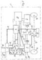
- a vehicle designated overall by 1 has an internal combustion engine drive with an internal combustion engine 2, the all auxiliary units necessary for its function, e.g. B. starter, Alternator, accumulator, fuel metering device, Ignition device, voltage regulator, etc. contains. These well-known Auxiliary units are not shown in the drawing.
- the internal combustion engine drive system is also used in the following Internal combustion engine 2 called.
- the vehicle further contains 1 a fuel cell system drive with a known structure. Of these fuel cell system drives known for motor vehicles are the gas generating device in the drawing 3, the fuel cell 4, and the electric drive motor 5 and an exhaust gas purification unit 6 are shown. From the gas generator 3 runs a connecting line 7 for hydrogen-containing gas to the fuel cell 4.
- a Line 8 is fed to the fuel cell 4 reaction air.
- a line 9 for the discharge runs from the fuel cell 4 the residual air or exhaust gases to the exhaust gas cleaning unit 6.
- An exhaust pipe 10 connects the gas generating device 3 with the exhaust gas purification unit 6 to which the Vehicle exhaust 18 is connected.
- the electric travel motor 5 is via a clutch 11 and a differential 12 connected to the propeller shaft 13, which is another Differential 14 drives the axle 15 with the wheels 16.
- the internal combustion engine 2 is connected to the differential via a clutch 17 12 connected.
- the internal combustion engine 2 and the fuel cell 4 have a common cooling circuit with a cooler 19.
- the fuel cell 4 is in particular an H 2 / O 2 fuel cell with a proton-conducting membrane, a so-called PEM cell, and is composed of a stack of individual fuel cells.
- the lines 20 between the internal combustion engine 2 and the cooler 19, between the internal combustion engine 2 and the fuel cell 4 and between the fuel cell 4 and the cooler 19 are shown in the drawing.
- An exhaust pipe 21 runs from the internal combustion engine 2 to Gas generating device 3, in which the exhaust pipe z. B. in Form of a heating coil 22 is passed. From the heating coil 22, an exhaust pipe 23 runs between the gas generating device 3 and the exhaust gas purification unit 6. From the Exhaust line 21 branches off a bypass line 24 with which the Gas generating device 3 is bypassed. In the bypass line 24 is a shut-off element 25, for. B. a flap, a valve or a slide.
- the vehicle 1 has a fuel tank 26 in which for example, liquid methanol.
- the fuel in Tank 26 is used both for supplying the internal combustion engine 2 as well as used to supply the fuel cell 4.
- the fuel line to the internal combustion engine 2 is in the Drawing not shown.
- On the internal combustion engine 2 are schematically an input 27 for air and an input 28 for the Fuel shown, the z. B. in one to the internal combustion engine 2 belonging, unspecified mixture formers are arranged.
- the gas generating device 3 is the fuel via a Line not shown to a schematically shown Input 29 supplied. Air becomes the gas generating device 3 via a schematically illustrated input 30 fed.
- the Fuel cell 4 required hydrogen separated from the fuel.
- the gas generating device 3 an evaporator in a manner known per se, in which the Fuel and water from a water reservoir, not shown converted into a gaseous state and then be directed to a reformer, in which means a hydrogen-containing gas is formed by a catalytic burner is separated from the residual gas, which via the Exhaust pipe 10 is discharged.
- the hydrogen-containing gas and Air is supplied under pressure to the fuel cell 4 in the the electrical required for the operation of the electric motor 5 Energy is generated.
- a controller 31 which among other things, a steep for the Includes electric drive motor 5, is unspecified Lines with the electric drive motor 5, the electrical units the internal combustion engine 2, at least one temperature sensor in the gas generating device 3, the fuel cell 4, the shut-off element 25, the clutch 17 and the clutch 11 connected.
- the internal combustion engine 2 has, for. B. a drive power of 30 kW, while the electric drive motor 5 has a drive power of 70 kW.
- the gas generating device 3 Made for heating the gas generating device 3 the cold state to the required operating temperature from the exhaust gases of the internal combustion engine 2 also by means of a Heat exchanger can be obtained, the other heat transfer medium than the exhaust gases in the gas generating device 3 circulates.
- the exhaust gases from the internal combustion engine 2 pass after passing through the heating coil 22 the exhaust pipe 23 into the exhaust gas purification unit 6 and from there via the exhaust 18 to the outside.
- the internal combustion engine 2 is caused by the circulation of coolant, which is also about the fuel cell 4 is directed in the cooler 19 on a for the operation kept favorable value.
- the fuel cell 4 will also on z. B. heated to 80 ° C to 90 ° C.
- the controller 31 monitors the temperature in the gas generating device 3. When the gas generating device 3 is at its operating temperature reached, it is controlled by the controller 31 automatically put into operation by adding air and fuel become. For example, for the air and fuel supply Compressors, not shown, provided by Accumulator and the alternator of the internal combustion engine 2 be fed. Since the gas generating device 3 and Fuel cell 4 already has its operating temperatures at this point have within a few seconds of the fuel cell 4 Generates electricity, which leads to the aggregates of the fuel cell system and the electric drive motor 5 is powered become. The controller 31 actuates the clutch 11, opens the clutch 17 and switches the internal combustion engine 2 off. The Vehicle 1 is now driven by electric motor 5. The Bypass line 24 is still blocked. The gas generating device 3 generates the necessary for its operation Heat itself. The operating condition described above is shown in Fig. 2 and based on the positions of the couplings 11, 12 recognizable.
- the vehicle 1 is then the internal combustion engine 2 and the Electric motor 5 driven.
- the bypass line 24 is permeable, causing an undesirably high heating of the gas generating device 3 is avoided.
Landscapes
- Engineering & Computer Science (AREA)
- Mechanical Engineering (AREA)
- Transportation (AREA)
- Life Sciences & Earth Sciences (AREA)
- Sustainable Development (AREA)
- Sustainable Energy (AREA)
- Chemical & Material Sciences (AREA)
- Combustion & Propulsion (AREA)
- Power Engineering (AREA)
- Manufacturing & Machinery (AREA)
- General Chemical & Material Sciences (AREA)
- Electrochemistry (AREA)
- Chemical Kinetics & Catalysis (AREA)
- Electric Propulsion And Braking For Vehicles (AREA)
- Fuel Cell (AREA)
- Output Control And Ontrol Of Special Type Engine (AREA)
- Hybrid Electric Vehicles (AREA)
Abstract
Description
- Fig. 1
- eine Prizipdarstellung eines Fahrzeugs mit einem Brennkraftmaschinen-Antrieb und einem Brennstoffzellensystems-Antrieb in einem ersten Betriebszustand,
- Fig. 2
- das in Fig. 1 dargestellte Fahrzeug in einem zweiten Betriebszustand,
- Fig. 3
- das in Fig. 1 dargestellte Fahrzeug in einem dritten Betriebszustand.
Claims (16)
- Fahrzeug (1) mit wenigstens einem Antriebsstrang für Antriebsräder (16) und mit einem an den Antriebsstrang ankuppelbaren Brennkraftmaschinen-Antrieb (2) sowie mit einem Brennstoffzellensystem, das eine Brennstoffzelle (4) und eine Gaserzeugungseinrichtung (3) aufweist, die bei höheren Temperaturen aus einem Kraftstoffwasserstoffhaltiges Gas für die Brennstoffzelle (4) erzeugt, wobei Einrichtungen für die Überleitung von Wärme aus dem Brennkrafmaschinen-Antrieb in die Gaserzeugungseinrichtung (3) und in die Brennstoffzelle (4) und eine Steuerung (31) vorgesehen sind, von der automatisch Aggregate für die Zufuhr von Kraftstoff und Luft zum Brennstoffzellensystem nach dem Aufheizen der Gaserzeugungseinrichtung (3) und der Brennstoffzelle (4) auf Arbeitstemperatur einschaltbar sind.
- Fahrzeug nach Anspruch 1, dadurch gekennzeichnet, daß wenigstens ein an den Antriebsstrang ankuppelbaren Elektrofahrmotor (5) vorgesehen ist.
- Fahrzeug nach Anspruch 1 oder 2, dadurch gekennzeichnet, daß für die Energieversorgung des Brennkraftmaschinen-Antriebs und des Brennstoffzellensystems flüssiger Krafstoff vorgesehen ist.
- Fahrzeug nach Anspruch 2, dadurch gekennzeichnet, daß nach der Funktionsaufnahme der Brennstoffzelle (4) der Elektrofahrmotor (5) an den Antriebsstrang automatisch ankuppelbar oder die manuell oder durch Fußpedal durchzuführende Kupplung des Elektrofahrmotors (5) mit dem Antriebsstrang freigebbar ist.
- Fahrzeug nach Anspruch 2, 3 oder 4, dadurch gekennzeichnet, daß die Nennleistung des Brennkraftmaschinen-Antriebs (2) kleiner als die Nennleistung des Elektrofahrmotors (5) ist.
- Fahrzeug nach zumindest einem der Ansprüche 2 bis 5, dadurch gekennzeichnet, daß der Brennkraftmaschinen-Antrieb (2) und der Brennstoffzellensystem-Antrieb in einem Kühlkreislauf gemeinsam an einen Kühler (19) angeschlossen sind.
- Fahrzeug nach zumindest einem der vorangegangenen Ansprüche, dadurch gekennzeichnet, daß eine Einrichtung zur Überleitung von Wärme aus den Abgasen des Brennkraftmaschinen-Antriebs (2) in die Gaserzeugungseinrichtung (3) vorgesehen ist.
- Fahrzeug nach Anspruch 7, dadurch gekennzeichnet, daß die Einrichtung zur Überleitung von Wärme eine im Innern der Gaserzeugung (3) verlaufende Leitung (22) für die Abgasrückführung ist.
- Fahrzeug nach zumindest einen der vorhergehenden Ansprüche, dadurch gekennzeichnet, daß parallel zu der Einrichtung für die Überleitung von Wärme aus den Abgasen des Brennkraftmaschinen-Antriebs (1) in die Gaserzeugungseinrichtung (3) ein außerhalb der Gaserzeugungseinrichtung verlaufender Bypass (24) angeordnet ist, der ein von der Steuerung (31) betätigbares Sperrelement (25) aufweist.
- Fahrzeug nach zumindest einem der vorhergehenden Ansprüche, dadurch gekennzeichnet, daß der Brennkraftmaschinen-Antrieb (2) und der Brennstoffzellensystem-Antrieb an einen gemeinsamen Abgasreiniger (6) angeschlossen sind.
- Verfahren zum Betrieb eines Fahrzeugs mit wenigstens einem Antriebsstrang und mit einem an den Antriebsstrang ankuppelbaren Brennkraftmaschinen-Antrieb sowie mit einen Brennstoffzellensystem, das eine Brennstoffzelle und eine Gaserzeugungseinrichtung aufweist, die bei höheren Temperaturen aus einen flüssigen Kraftstoff wasserstoffhaltiges Gas für die Brennstoffzelle erzeugt, wobei der Brennkraftmaschinen-Antrieb mit flüssigem Kraftstoff betrieben und nach dem Starten der Brennkraftmaschine an den Antriebsstrang zur Fortbewegung des Fahrzeugs ankuppelbar ist, während die von der Brennkraftmaschine erzeugten heißen Abgase direkt und/oder indirekt das Brennstoffzellensystem auf eine wenigstens für die Funktion ausreichende Temperatur aufheizen, bei deren Erreichen das Brennstoffzellensystem durch Zufuhr von Kraftstoff und Luft in Gang gesetzt wird.
- Verfahren nach Anspruch 8, dadurch gekennzeichnet, daß das Brennstoffzellensystem einen an den Antriebsstrang ankuppelbaren Elektrofahrmotor aufweist, der nach dem Erreichen der Betriebstemperatur des Brennstoffzellensystem automatisch an den Antriebsstrang ankuppelt wird oder daß eine Kupplung des Elektrofahrmotors zum Antriebsstrang für die Fuß- oder Handbetätigung freigegeben wird und der Brennkraftmaschinen-Antrieb wahlweise vom Antriebsstrang abgekoppelt wird.
- Verfahren nach Anspruch 11, dadurch gekennzeichnet, daß der Brennkraftmaschinen-Antrieb und Brennstoffzellensystem-Antrieb gemeinsam auf den Antriebestrang einwirken.
- Verfahren nach Anspruch 11, dadurch gekennzeichnet, daß der Brennstoffzellensystem-Antrieb nach der Funktionsaufnahme der Brennstoffzelle alleine auf den Antriebsstrang einwirkt.
- Verfahren nach zumindest einen der vorhergehenden Ansprüche, dadurch gekennzeichnet, daß die Brennstoffzelle und der Brennkraftmaschinen-Antrieb gemeinsam auf eine Betriebstemperatur gekühlt werden.
- Verfahren nach zumindest einen der vorhergehenden Ansprüche, dadurch gekennzeichnet, daß ein zu einer Einrichtung in der Gaserzeugungseinrichtung für die Überleitung der Wärme paralleler Bypass außerhalb der Gaserzeugungseinrichtung beim Betrieb der Brennkraftmaschine und nicht in Betrieb befindlicher Brennstoffzelle sowie bei arbeitender Brennstoffzelle und nicht im Betrieb befindlicher Brennkraftmaschine gesperrt wird und bei zugleich arbeitender Brennkraftmaschine und Brennstoffzelle durchlässig gesteuert wird.
Applications Claiming Priority (2)
| Application Number | Priority Date | Filing Date | Title |
|---|---|---|---|
| DE19913794 | 1999-03-26 | ||
| DE19913794A DE19913794C2 (de) | 1999-03-26 | 1999-03-26 | Fahrzeug mit einem Antriebsstrang für wenigstens zwei Antriebsräder und mit einem Brennkraftmaschinen-Antrieb sowie mit einem Brennstoffzellensystem |
Publications (3)
| Publication Number | Publication Date |
|---|---|
| EP1038713A2 true EP1038713A2 (de) | 2000-09-27 |
| EP1038713A3 EP1038713A3 (de) | 2000-12-27 |
| EP1038713B1 EP1038713B1 (de) | 2002-09-11 |
Family
ID=7902539
Family Applications (1)
| Application Number | Title | Priority Date | Filing Date |
|---|---|---|---|
| EP00101306A Expired - Lifetime EP1038713B1 (de) | 1999-03-26 | 2000-01-22 | Fahrzeug mit einem Antriebsstrang für wenigstens zwei Antriebsräder und mit einem Brennkraftmaschinen-Antrieb sowie mit einem Brennstoffzellensystem |
Country Status (3)
| Country | Link |
|---|---|
| US (1) | US6276473B1 (de) |
| EP (1) | EP1038713B1 (de) |
| DE (2) | DE19913794C2 (de) |
Cited By (3)
| Publication number | Priority date | Publication date | Assignee | Title |
|---|---|---|---|---|
| EP1774142A4 (de) * | 2004-07-22 | 2009-03-04 | Sprint Communications Co | Kraftstoffsystem für kühlzwecke |
| WO2024132954A1 (fr) * | 2022-12-21 | 2024-06-27 | Ampere S.A.S. | Système thermique pour véhicule automobile |
| CN118927995A (zh) * | 2024-07-05 | 2024-11-12 | 佛山仙湖实验室 | 基于氢燃料的热-电复合零碳动力驱动系统及控制方法 |
Families Citing this family (50)
| Publication number | Priority date | Publication date | Assignee | Title |
|---|---|---|---|---|
| US6892840B2 (en) * | 1999-05-05 | 2005-05-17 | Daniel J. Meaney, Jr. | Hybrid electric vehicle having alternate power sources |
| US6489052B1 (en) * | 1999-11-18 | 2002-12-03 | Plug Power Inc. | Fuel cell air purification subsystem |
| DE10019770B4 (de) * | 2000-04-20 | 2006-12-07 | Nucellsys Gmbh | Verfahren zur Verbesserung des Anspringverhaltens von mobilen Brennstoffzellensystemen |
| DE10054007A1 (de) * | 2000-11-01 | 2002-06-06 | Xcellsis Gmbh | Kraftfahrzeug mit einem Antriebsverbrennungsmotor |
| DE10058020B4 (de) * | 2000-11-23 | 2013-09-12 | Burani Consulting Limited Liability Company | Kraftfahrzeugantrieb |
| JP3771441B2 (ja) * | 2000-12-05 | 2006-04-26 | 本田技研工業株式会社 | 燃料電池搭載自動車 |
| DE10065305A1 (de) | 2000-12-29 | 2002-07-18 | Siemens Ag | Kraftfahrzeug mit einem Verbrennungsmotor und einer Bordstromversorgung |
| DE10113000A1 (de) | 2001-03-17 | 2002-09-19 | Bayerische Motoren Werke Ag | System aus Verbrennungsmotor und Brennstoffzelle |
| US6861169B2 (en) * | 2001-05-09 | 2005-03-01 | Nuvera Fuel Cells, Inc. | Cogeneration of power and heat by an integrated fuel cell power system |
| US8397852B1 (en) | 2001-07-03 | 2013-03-19 | Raymond Earl Perry | Multiple-mode vehicle power system |
| US6571897B2 (en) * | 2001-08-13 | 2003-06-03 | Ballard Power Systems Ag | Vehicle with a fuel cell system and method for operating the same |
| DE10152809B4 (de) * | 2001-10-25 | 2004-07-22 | Daimlerchrysler Ag | Verfahren zum Betreiben eines Hybridantriebssystems |
| FR2832550B1 (fr) * | 2001-11-21 | 2004-08-20 | Renault | Procede et dispositif de gestion energetique de trajets courts d'un vehicule a pile a combustible |
| US20030176951A1 (en) * | 2002-01-09 | 2003-09-18 | Demarchi Julian A. | System integrating a reformer and a fuel cell system |
| EP1476524B1 (de) * | 2002-02-19 | 2008-11-19 | International Inc. Honeywell | Wärmeträger mit hohem elektrischem widerstand für brennstoffzellaggregate |
| DE10227530A1 (de) | 2002-06-20 | 2004-04-01 | Daimlerchrysler Ag | Kraftfahrzeug |
| DE10232737B4 (de) * | 2002-07-19 | 2005-12-08 | Audi Ag | Kraftfahrzeugaggregat |
| DE10244883B4 (de) * | 2002-09-26 | 2005-02-17 | J. Eberspächer GmbH & Co. KG | Heizsystem für ein Fahrzeug |
| US20040089485A1 (en) * | 2002-11-08 | 2004-05-13 | Kramer Dennis A. | Vehicle drive arrangement having multiple-sized electric motors |
| NL1022589C2 (nl) * | 2003-02-05 | 2004-08-06 | Tno | Voertuig. |
| US7198124B2 (en) * | 2003-03-05 | 2007-04-03 | Ford Motor Company | Vehicle and energy producing and storage system for a vehicle |
| DE10349899B4 (de) * | 2003-10-25 | 2015-02-12 | Audi Ag | Verfahren zur Regeneration eines Partikelfilters |
| US7081687B2 (en) * | 2004-07-22 | 2006-07-25 | Sprint Communications Company L.P. | Power system for a telecommunications facility |
| FR2874247B1 (fr) * | 2004-08-12 | 2007-03-16 | Air Liquide | Systeme stockage de gaz, procede de mise en oeuvre et vehicule incorporant un tel systeme |
| JP5013034B2 (ja) * | 2004-09-07 | 2012-08-29 | トヨタ自動車株式会社 | 燃料電池システム |
| US8463529B2 (en) | 2004-09-17 | 2013-06-11 | Eaton Corporation | System and method of operating internal combustion engines at fuel rich low-temperature- combustion mode as an on-board reformer for solid oxide fuel cell-powered vehicles |
| US7818959B2 (en) * | 2004-09-17 | 2010-10-26 | Eaton Corporation | Clean power system |
| US7648785B2 (en) * | 2004-09-17 | 2010-01-19 | Eaton Corporation | Clean power system |
| DE102004062152A1 (de) | 2004-12-23 | 2006-07-13 | Bayerische Motoren Werke Ag | System aus einer Brennstoffzelle und einer Brennkraftmaschine |
| US7213397B2 (en) * | 2005-02-07 | 2007-05-08 | Eaton Corporation | Mechanism and method of combined fuel reformer and dosing system for exhaust aftertreatment and anti-idle SOFC APU |
| EP1739777B1 (de) | 2005-06-28 | 2014-01-22 | Eberspächer Climate Control Systems GmbH & Co. KG. | Brennstoffzellensystem für ein Fahrzeug |
| DE102005030474A1 (de) * | 2005-06-28 | 2007-01-04 | J. Eberspächer GmbH & Co. KG | Brennstoffzellensystem für ein Fahrzeug |
| DE102006054669A1 (de) | 2006-11-17 | 2008-06-05 | J. Eberspächer GmbH & Co. KG | Hybrid-Antrieb für ein Kraftfahrzeug |
| JP5234401B2 (ja) * | 2007-12-06 | 2013-07-10 | 日産自動車株式会社 | 固体電解質型燃料電池システム |
| JP4580994B2 (ja) * | 2008-02-07 | 2010-11-17 | 本田技研工業株式会社 | 高圧タンク |
| WO2011014513A1 (en) * | 2009-07-30 | 2011-02-03 | Hybrid Kinetic Automotive Holdings | Multi-fuel and electric-drive hybrid power train and vehicle using the same |
| WO2013025650A1 (en) * | 2011-08-12 | 2013-02-21 | Mcalister Technologies, Llc | Mobile transport platforms for producing hydrogen and structural materials and associated systems and methods |
| WO2013084273A1 (ja) * | 2011-12-09 | 2013-06-13 | トヨタ自動車株式会社 | 内燃機関 |
| DE102012211421A1 (de) * | 2012-07-02 | 2014-05-22 | Bayerische Motoren Werke Aktiengesellschaft | Abluftführung eines Brennstoffzellenstacks in einem Kraftfahrzeug |
| US9205834B1 (en) * | 2014-06-27 | 2015-12-08 | Toyota Motor Engineering & Manufacturing North America, Inc. | Reconfigurable system with minimum mobility mode |
| US10145316B2 (en) | 2016-05-04 | 2018-12-04 | Ford Global Technologies, Llc | Method and system for engine control |
| US9873435B2 (en) | 2016-05-04 | 2018-01-23 | Ford Global Technologies, Llc | Method and system for engine control |
| US10060362B2 (en) | 2016-05-04 | 2018-08-28 | Ford Global Technologies, Llc | Method and system for engine control |
| US9925975B2 (en) | 2016-05-04 | 2018-03-27 | Ford Global Technologies, Llc | Method and system for hybrid vehicle control |
| US9944276B2 (en) | 2016-05-04 | 2018-04-17 | Ford Global Technologies, Llc | Method and system for engine control |
| US9776624B1 (en) | 2016-05-04 | 2017-10-03 | Ford Global Technologies, Llc | Method and system for engine control |
| CN114435115B (zh) * | 2020-11-06 | 2024-03-08 | 上海汽车集团股份有限公司 | 一种混合动力汽车及其热管理系统 |
| CN113921858A (zh) * | 2021-09-26 | 2022-01-11 | 北京亿华通科技股份有限公司 | 氢内燃机系统、氢燃料电池系统联合的冷启动方法及装置 |
| KR20240007517A (ko) * | 2022-07-08 | 2024-01-16 | 현대자동차주식회사 | 연료전지 시스템 |
| FR3142949B1 (fr) * | 2022-12-12 | 2024-11-29 | Renault | Groupe motopropulseur hybride de vehicule automobile comportant une pile a combustible |
Family Cites Families (14)
| Publication number | Priority date | Publication date | Assignee | Title |
|---|---|---|---|---|
| JPS5031516A (de) * | 1973-07-24 | 1975-03-28 | ||
| US4271664A (en) * | 1977-07-21 | 1981-06-09 | Hydragon Corporation | Turbine engine with exhaust gas recirculation |
| US4226294A (en) * | 1978-11-06 | 1980-10-07 | R & D Associates | Engine system using liquid air and combustible fuel |
| US4583512A (en) * | 1983-02-22 | 1986-04-22 | Gardner Paul R | Fuel feed and fuel vaporization system |
| US5200278A (en) * | 1991-03-15 | 1993-04-06 | Ballard Power Systems, Inc. | Integrated fuel cell power generation system |
| JPH04349357A (ja) * | 1991-05-27 | 1992-12-03 | Fuji Electric Co Ltd | 熱併給燃料電池 |
| US5228529A (en) * | 1991-12-17 | 1993-07-20 | Stuart Rosner | Method for renewing fuel cells using magnesium anodes |
| US5366821A (en) * | 1992-03-13 | 1994-11-22 | Ballard Power Systems Inc. | Constant voltage fuel cell with improved reactant supply and control system |
| DE4412451C1 (de) * | 1994-04-12 | 1995-09-28 | Daimler Benz Ag | Anordnung eines Antriebsaggregats in einem Elektrofahrzeug |
| EP0741428A1 (de) * | 1995-05-04 | 1996-11-06 | FINMECCANICA S.p.A. AZIENDA ANSALDO | Zuführungssystem für Brennstoffzellen der Art SPE (Festpolymerelektrolyt) für Hybridfahrzeugen |
| US5771476A (en) * | 1995-12-29 | 1998-06-23 | Dbb Fuel Cell Engines Gmbh | Power control system for a fuel cell powered vehicle |
| US6186254B1 (en) * | 1996-05-29 | 2001-02-13 | Xcelliss Fuel Cell Engines Inc. | Temperature regulating system for a fuel cell powered vehicle |
| US5899175A (en) * | 1997-03-14 | 1999-05-04 | Procyon Power Systems, Inc. | Hybrid electric-combustion power plant |
| US6053266A (en) * | 1997-12-01 | 2000-04-25 | Dbb Fuel Cell Engines Gmbh | Fuel cell engine having a propulsion motor operatively connected to drive a fluid supply device |
-
1999
- 1999-03-26 DE DE19913794A patent/DE19913794C2/de not_active Expired - Fee Related
-
2000
- 2000-01-22 EP EP00101306A patent/EP1038713B1/de not_active Expired - Lifetime
- 2000-01-22 DE DE50000466T patent/DE50000466D1/de not_active Expired - Lifetime
- 2000-03-27 US US09/536,294 patent/US6276473B1/en not_active Expired - Lifetime
Cited By (4)
| Publication number | Priority date | Publication date | Assignee | Title |
|---|---|---|---|---|
| EP1774142A4 (de) * | 2004-07-22 | 2009-03-04 | Sprint Communications Co | Kraftstoffsystem für kühlzwecke |
| WO2024132954A1 (fr) * | 2022-12-21 | 2024-06-27 | Ampere S.A.S. | Système thermique pour véhicule automobile |
| FR3144060A1 (fr) * | 2022-12-21 | 2024-06-28 | Renault S.A.S | Système thermique pour véhicule automobile. |
| CN118927995A (zh) * | 2024-07-05 | 2024-11-12 | 佛山仙湖实验室 | 基于氢燃料的热-电复合零碳动力驱动系统及控制方法 |
Also Published As
| Publication number | Publication date |
|---|---|
| US6276473B1 (en) | 2001-08-21 |
| DE19913794C2 (de) | 2002-11-14 |
| DE19913794A1 (de) | 2000-10-12 |
| EP1038713B1 (de) | 2002-09-11 |
| EP1038713A3 (de) | 2000-12-27 |
| DE50000466D1 (de) | 2002-10-17 |
Similar Documents
| Publication | Publication Date | Title |
|---|---|---|
| EP1038713B1 (de) | Fahrzeug mit einem Antriebsstrang für wenigstens zwei Antriebsräder und mit einem Brennkraftmaschinen-Antrieb sowie mit einem Brennstoffzellensystem | |
| DE19928102B4 (de) | Fahrzeug mit einem Antriebs-Verbrennungsmotor und mit einem Brennstoffzellensystem zur Stromversorgung elektrischer Verbraucher des Fahrzeugs und Verfahren zum Betrieb eines derartigen Fahrzeugs | |
| EP1203697B1 (de) | Kraftfahrzeug mit einem Antriebsverbrennungsmotor | |
| DE112005001368B4 (de) | Thermoelektrisch verstärktes, hybrid-elektrisches Antriebssystem | |
| DE10248611B4 (de) | System und Verfahren zum selektiven Beheizen von Brennstoffzellen | |
| EP1923288B1 (de) | Hybrid-Antrieb mit Brennstoffzelle für ein Kraftfahrzeug | |
| DE19913795C1 (de) | Vorrichtung mit einer Brennkraftmaschine und mit einem Brennstoffzellensystem | |
| DE102017211303B4 (de) | Wärmespeicheranordnung für eine Fahrzeugbatterie und Verfahren zu deren Betrieb | |
| DE102010012464A1 (de) | Heizeinrichtung zum Beheizen eines Fahrzeuginnenraums eines Fahrzeugs | |
| DE10301667B4 (de) | Einrichtung zum Konditionieren eines Fahrzeugs | |
| DE3432512A1 (de) | Verfahren und vorrichtung zum vergluehen einer brennkraftmaschine oder der brennkraftmaschinenansaugluft | |
| DE10007244A1 (de) | Vorrichtung zur Wasserrückgewinnung für ein Bordstrom-Brennstoffzellensystem | |
| DE10203311B4 (de) | Brennstoffzellensystem und Verfahren zum Betreiben desselben | |
| DE10258196A1 (de) | System mit einem Verbrennungsmotor und einer Brennstoffzelle | |
| WO2010063368A1 (de) | Kraftfahrzeug mit einer abwärmenutzungsvorrichtung zur einspeisung der abwärme in nutzbare mechanische arbeit | |
| DE10142923A1 (de) | Hybridantriebsvorrichtung und Verfahren zum Betreiben der Hybridantriebsvorrichtung | |
| EP1123823A2 (de) | Energieerzeuger für Rad- und Kettenfahrzeuge zum Einsatz in arktischen Klimazonen | |
| DE102007037350A1 (de) | Verfahren zum Betreiben einer Antriebsvorrichtung sowie Antriebsvorrichtung | |
| DE10322296A1 (de) | Luftversorgungseinrichtung für ein Brennstoffzellensystem | |
| DE20320913U1 (de) | Reformer-Brennstoffzellen-System für mobile Räume | |
| DE102011000951B4 (de) | Fahrzeug, insbesondere militärisches Fahrzeug, mit einer Vorrichtung zum Temperieren von Fahrzeugkomponenten. | |
| DE102009005638B4 (de) | Fahrzeugtemperiersystem, insbesondere zur thermischen Behandlung der in einen Fahrzeuginnenraum einzuleitenden Luft | |
| DE112019000288T5 (de) | Anordnung und Verfahren zur Steuerung eines Abwärmerückgewinnungssystems | |
| DE10201930A1 (de) | Kraftfahrzeug mit einer Brennkraftmaschine und einem Brennstoffzellensystem | |
| DE102022000430A1 (de) | Brennstoffzellensystem für ein Brennstoffzellenfahrzeug |
Legal Events
| Date | Code | Title | Description |
|---|---|---|---|
| PUAI | Public reference made under article 153(3) epc to a published international application that has entered the european phase |
Free format text: ORIGINAL CODE: 0009012 |
|
| AK | Designated contracting states |
Kind code of ref document: A2 Designated state(s): DE FR GB IT |
|
| AX | Request for extension of the european patent |
Free format text: AL;LT;LV;MK;RO;SI |
|
| PUAL | Search report despatched |
Free format text: ORIGINAL CODE: 0009013 |
|
| AK | Designated contracting states |
Kind code of ref document: A3 Designated state(s): AT BE CH CY DE DK ES FI FR GB GR IE IT LI LU MC NL PT SE |
|
| AX | Request for extension of the european patent |
Free format text: AL;LT;LV;MK;RO;SI |
|
| RIC1 | Information provided on ipc code assigned before grant |
Free format text: 7B 60K 6/00 A, 7B 60K 6/04 B |
|
| 17P | Request for examination filed |
Effective date: 20001205 |
|
| 17Q | First examination report despatched |
Effective date: 20010226 |
|
| AKX | Designation fees paid |
Free format text: DE FR GB IT |
|
| GRAG | Despatch of communication of intention to grant |
Free format text: ORIGINAL CODE: EPIDOS AGRA |
|
| GRAG | Despatch of communication of intention to grant |
Free format text: ORIGINAL CODE: EPIDOS AGRA |
|
| GRAH | Despatch of communication of intention to grant a patent |
Free format text: ORIGINAL CODE: EPIDOS IGRA |
|
| GRAG | Despatch of communication of intention to grant |
Free format text: ORIGINAL CODE: EPIDOS AGRA |
|
| GRAH | Despatch of communication of intention to grant a patent |
Free format text: ORIGINAL CODE: EPIDOS IGRA |
|
| GRAH | Despatch of communication of intention to grant a patent |
Free format text: ORIGINAL CODE: EPIDOS IGRA |
|
| RAP1 | Party data changed (applicant data changed or rights of an application transferred) |
Owner name: BALLARD POWER SYSTEMS AG |
|
| GRAA | (expected) grant |
Free format text: ORIGINAL CODE: 0009210 |
|
| AK | Designated contracting states |
Kind code of ref document: B1 Designated state(s): DE FR GB IT |
|
| REG | Reference to a national code |
Ref country code: GB Ref legal event code: FG4D Free format text: NOT ENGLISH |
|
| REF | Corresponds to: |
Ref document number: 50000466 Country of ref document: DE Date of ref document: 20021017 |
|
| GBT | Gb: translation of ep patent filed (gb section 77(6)(a)/1977) |
Effective date: 20021108 |
|
| ET | Fr: translation filed | ||
| PLBE | No opposition filed within time limit |
Free format text: ORIGINAL CODE: 0009261 |
|
| STAA | Information on the status of an ep patent application or granted ep patent |
Free format text: STATUS: NO OPPOSITION FILED WITHIN TIME LIMIT |
|
| 26N | No opposition filed |
Effective date: 20030612 |
|
| REG | Reference to a national code |
Ref country code: FR Ref legal event code: CD Ref country code: FR Ref legal event code: TP |
|
| PGFP | Annual fee paid to national office [announced via postgrant information from national office to epo] |
Ref country code: DE Payment date: 20130328 Year of fee payment: 14 |
|
| PGFP | Annual fee paid to national office [announced via postgrant information from national office to epo] |
Ref country code: GB Payment date: 20130701 Year of fee payment: 14 Ref country code: FR Payment date: 20130722 Year of fee payment: 14 |
|
| PGFP | Annual fee paid to national office [announced via postgrant information from national office to epo] |
Ref country code: IT Payment date: 20130628 Year of fee payment: 14 |
|
| REG | Reference to a national code |
Ref country code: DE Ref legal event code: R119 Ref document number: 50000466 Country of ref document: DE |
|
| GBPC | Gb: european patent ceased through non-payment of renewal fee |
Effective date: 20140122 |
|
| REG | Reference to a national code |
Ref country code: DE Ref legal event code: R119 Ref document number: 50000466 Country of ref document: DE Effective date: 20140801 |
|
| PG25 | Lapsed in a contracting state [announced via postgrant information from national office to epo] |
Ref country code: DE Free format text: LAPSE BECAUSE OF NON-PAYMENT OF DUE FEES Effective date: 20140801 |
|
| REG | Reference to a national code |
Ref country code: FR Ref legal event code: ST Effective date: 20140930 |
|
| PG25 | Lapsed in a contracting state [announced via postgrant information from national office to epo] |
Ref country code: FR Free format text: LAPSE BECAUSE OF NON-PAYMENT OF DUE FEES Effective date: 20140131 Ref country code: GB Free format text: LAPSE BECAUSE OF NON-PAYMENT OF DUE FEES Effective date: 20140122 |
|
| PG25 | Lapsed in a contracting state [announced via postgrant information from national office to epo] |
Ref country code: IT Free format text: LAPSE BECAUSE OF NON-PAYMENT OF DUE FEES Effective date: 20140122 |