EP1038634A2 - Method for removing edge areas of a laminated panel - Google Patents
Method for removing edge areas of a laminated panel Download PDFInfo
- Publication number
- EP1038634A2 EP1038634A2 EP00302101A EP00302101A EP1038634A2 EP 1038634 A2 EP1038634 A2 EP 1038634A2 EP 00302101 A EP00302101 A EP 00302101A EP 00302101 A EP00302101 A EP 00302101A EP 1038634 A2 EP1038634 A2 EP 1038634A2
- Authority
- EP
- European Patent Office
- Prior art keywords
- grinding wheel
- wheel
- panel
- edge
- pressure
- Prior art date
- Legal status (The legal status is an assumption and is not a legal conclusion. Google has not performed a legal analysis and makes no representation as to the accuracy of the status listed.)
- Withdrawn
Links
Images


Classifications
-
- B—PERFORMING OPERATIONS; TRANSPORTING
- B24—GRINDING; POLISHING
- B24B—MACHINES, DEVICES, OR PROCESSES FOR GRINDING OR POLISHING; DRESSING OR CONDITIONING OF ABRADING SURFACES; FEEDING OF GRINDING, POLISHING, OR LAPPING AGENTS
- B24B9/00—Machines or devices designed for grinding edges or bevels on work or for removing burrs; Accessories therefor
- B24B9/02—Machines or devices designed for grinding edges or bevels on work or for removing burrs; Accessories therefor characterised by a special design with respect to properties of materials specific to articles to be ground
- B24B9/06—Machines or devices designed for grinding edges or bevels on work or for removing burrs; Accessories therefor characterised by a special design with respect to properties of materials specific to articles to be ground of non-metallic inorganic material, e.g. stone, ceramics, porcelain
- B24B9/08—Machines or devices designed for grinding edges or bevels on work or for removing burrs; Accessories therefor characterised by a special design with respect to properties of materials specific to articles to be ground of non-metallic inorganic material, e.g. stone, ceramics, porcelain of glass
- B24B9/10—Machines or devices designed for grinding edges or bevels on work or for removing burrs; Accessories therefor characterised by a special design with respect to properties of materials specific to articles to be ground of non-metallic inorganic material, e.g. stone, ceramics, porcelain of glass of plate glass
- B24B9/107—Machines or devices designed for grinding edges or bevels on work or for removing burrs; Accessories therefor characterised by a special design with respect to properties of materials specific to articles to be ground of non-metallic inorganic material, e.g. stone, ceramics, porcelain of glass of plate glass for glass plates while they are turning
-
- B—PERFORMING OPERATIONS; TRANSPORTING
- B24—GRINDING; POLISHING
- B24B—MACHINES, DEVICES, OR PROCESSES FOR GRINDING OR POLISHING; DRESSING OR CONDITIONING OF ABRADING SURFACES; FEEDING OF GRINDING, POLISHING, OR LAPPING AGENTS
- B24B1/00—Processes of grinding or polishing; Use of auxiliary equipment in connection with such processes
-
- B—PERFORMING OPERATIONS; TRANSPORTING
- B24—GRINDING; POLISHING
- B24B—MACHINES, DEVICES, OR PROCESSES FOR GRINDING OR POLISHING; DRESSING OR CONDITIONING OF ABRADING SURFACES; FEEDING OF GRINDING, POLISHING, OR LAPPING AGENTS
- B24B9/00—Machines or devices designed for grinding edges or bevels on work or for removing burrs; Accessories therefor
- B24B9/02—Machines or devices designed for grinding edges or bevels on work or for removing burrs; Accessories therefor characterised by a special design with respect to properties of materials specific to articles to be ground
- B24B9/20—Machines or devices designed for grinding edges or bevels on work or for removing burrs; Accessories therefor characterised by a special design with respect to properties of materials specific to articles to be ground of plastics
-
- B—PERFORMING OPERATIONS; TRANSPORTING
- B26—HAND CUTTING TOOLS; CUTTING; SEVERING
- B26D—CUTTING; DETAILS COMMON TO MACHINES FOR PERFORATING, PUNCHING, CUTTING-OUT, STAMPING-OUT OR SEVERING
- B26D7/00—Details of apparatus for cutting, cutting-out, stamping-out, punching, perforating, or severing by means other than cutting
- B26D2007/0012—Details, accessories or auxiliary or special operations not otherwise provided for
- B26D2007/0068—Trimming and removing web edges
Definitions
- the elastomeric-plastic sheet is formed of a stretchable vinyl butyl material.
Landscapes
- Engineering & Computer Science (AREA)
- Mechanical Engineering (AREA)
- Chemical & Material Sciences (AREA)
- Ceramic Engineering (AREA)
- Inorganic Chemistry (AREA)
- Grinding And Polishing Of Tertiary Curved Surfaces And Surfaces With Complex Shapes (AREA)
Abstract
Description
Claims (14)
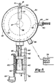
- A method of removing a protruding edge area (20) of an elastomeric-plastic sheet (18) in an automotive window safety panel (10), comprising the steps of:a) orienting the panel (10) normal to the plane of a grinding wheel (22), with the edge of the panel (10) in pressure contact with the edge of the wheel (22);b) rotating the grinding wheel (22); and,c) passing the panel (10) transversely across the edge surface of the wheel (22) so the entire peripheral edge of the panel (10) is contacted by the wheel (22).
- The method of claim 1, and further comprising:d) resiliently biasing the grinding wheel (22) toward the panel (10) during step (c), whereby the wheel (22) has continuous pressure contact with the protruding edge (20) of the plastic sheet (18).
- The method of claim 2, wherein step (d) is carried out with a fluid cylinder (40).
- The method of claim 2, wherein step (d) is carried out by varying the air pressure supplied to an air cylinder (40) operatively connected to the grinding wheel (22).
- The method of claim 4, wherein step (d) further comprises the step of sensing (46) the pressure of the grinding wheel (22) on the edge (20) of the elastomeric-plastic sheet (18), and using the sensed contact pressure (46) to control the air pressure supplied to the fluid cylinder (40).
- The method of claim 2, wherein step (d) is carried out so that there is a substantially constant pressure between the grinding wheel (22) and the edge (20) of the elastomeric-plastic sheet (18) during step (c).
- The method of claim 1, and further comprising (d) disposing said grinding wheel (22) in a vacuum chamber (30,38,39), whereby plastic fragments generated by the grinding wheel (22) are captured in the vacuum chamber.
- The method of claim 1, and further comprising (d) resiliently biasing the grinding wheel (22) toward the panel (10) along a pathline containing the panel plane, whereby the wheel (22) has continuous pressure contact with the protruding edge (20) of the plastic sheet (18) during step (c).
- The method of claim 8, whereby step (d) is carried out with a pressure-applying device (40) and pressure sensor (46) oriented parallel to the aforementioned pathline; said step (d) comprising the substeps of sensing the grinding wheel contact pressure with the pressure sensor, and using the sensed pressure to control the pressure-applying device (40).
- The method of claim 1, and further comprising the step of (d) varying the rotational velocity of the grinding wheel (22) so as to maintain a relatively constant edge surface (24) speed in spite of variations in grinding wheel (22) diameter due to wear.
- The method of claim 1, and further comprising the steps of (d) sensing (45) the variations in the diameter of the grinding wheel (22) due to wear, and (e) using the sensed wheel diameter variations to regulate the rotational velocity of the grinding wheel (22) so as to maintain a relatively constant wheel edge speed in spite of variations in the grinding wheel (22) diameter.
- The method of claim 1, wherein step (c) is carried out with a robotic manipulator.
- The method of claim 1, wherein step (c) is carried out with a programmable robotic manipulator.
- The method of claim 1, wherein step (c) is carried out with a programmable robotic manipulator, step (c) being accomplished with a computer program that causes the robotic manipulator to maintain the peripheral edge of the panel in continuous contact with the grinding wheel during step (c).
Applications Claiming Priority (2)
| Application Number | Priority Date | Filing Date | Title |
|---|---|---|---|
| US09/275,157 US6099385A (en) | 1999-03-24 | 1999-03-24 | Method for removing edge areas of a laminated panel |
| US275157 | 1999-03-24 |
Publications (2)
| Publication Number | Publication Date |
|---|---|
| EP1038634A2 true EP1038634A2 (en) | 2000-09-27 |
| EP1038634A3 EP1038634A3 (en) | 2003-05-07 |
Family
ID=23051103
Family Applications (1)
| Application Number | Title | Priority Date | Filing Date |
|---|---|---|---|
| EP00302101A Withdrawn EP1038634A3 (en) | 1999-03-24 | 2000-03-15 | Method for removing edge areas of a laminated panel |
Country Status (2)
| Country | Link |
|---|---|
| US (1) | US6099385A (en) |
| EP (1) | EP1038634A3 (en) |
Cited By (5)
| Publication number | Priority date | Publication date | Assignee | Title |
|---|---|---|---|---|
| EP1733843A1 (en) * | 2005-06-16 | 2006-12-20 | Peter Lisec | Method and device for the removal of the protruding edge of a plastic sheet of laminated glass panels |
| CN107553255A (en) * | 2017-09-27 | 2018-01-09 | 如皋市祥强机械设备有限公司 | A kind of device for deburring being used in rubber and plastic process |
| CN108162270A (en) * | 2018-01-28 | 2018-06-15 | 东莞市皓奇企业管理服务有限公司 | Using method of robot edge trimmer |
| CN108724008A (en) * | 2018-05-04 | 2018-11-02 | 芜湖良匠机械制造有限公司 | A kind of spray equipment rinsed for glass substrate rack edge |
| CN108723931A (en) * | 2018-05-28 | 2018-11-02 | 重庆雷钜电子科技有限公司 | Moulding deburring apparatus |
Families Citing this family (17)
| Publication number | Priority date | Publication date | Assignee | Title |
|---|---|---|---|---|
| US6565145B2 (en) * | 2000-12-01 | 2003-05-20 | Btr Robotic Limited | Adjustable automotive airfoil |
| US20030181145A1 (en) * | 2002-03-21 | 2003-09-25 | Collins Mark E. | Automotive safety glass edge polishing |
| US7018272B2 (en) * | 2003-07-29 | 2006-03-28 | Corning Incorporated | Pressure feed grinding of AMLCD substrate edges |
| US7125319B2 (en) | 2003-10-27 | 2006-10-24 | Corning Incorporated | Apparatus and method for grinding and/or polishing an edge of a glass sheet |
| US20050229763A1 (en) * | 2004-04-20 | 2005-10-20 | Xiao Alan | Pre-biasing device for urging movable member relative to fixed base |
| US7316604B1 (en) * | 2005-12-16 | 2008-01-08 | Global Aero Services, Inc. | Aircraft transparency polisher and/or surface refinisher |
| DE102008027050A1 (en) * | 2008-06-06 | 2009-12-10 | Grenzebach Maschinenbau Gmbh | Method and device for automatic edge grinding of glass plates under clean room conditions |
| US8585467B2 (en) | 2008-10-31 | 2013-11-19 | Corning Incorporated | Linear pressure feed grinding with voice coil |
| US8721392B2 (en) | 2011-06-28 | 2014-05-13 | Corning Incorporated | Glass edge finishing method |
| CN102990496B (en) * | 2012-12-04 | 2015-03-25 | 福耀玻璃工业集团股份有限公司 | Trimming method for automobile laminated glass |
| DE102014006225A1 (en) | 2014-04-30 | 2015-11-05 | Waldemar Knittel Glasbearbeitungs Gmbh | Method for processing a glass pane and glass pane processing device |
| KR102245175B1 (en) | 2016-10-12 | 2021-04-28 | 코닝 인코포레이티드 | Methods and Apparatus for Glass Laminate Edge Finishing and glass laminates formed thereby |
| CN110814897A (en) * | 2019-10-15 | 2020-02-21 | 广东博智林机器人有限公司 | Polishing robot |
| CN112338687A (en) * | 2020-11-09 | 2021-02-09 | 昆山同日机器人智能科技有限公司 | Metal ring burr polishing device and using method |
| CN113263388B (en) * | 2021-06-21 | 2022-06-21 | 安徽易全新材料有限公司 | High accuracy plastic products deburring device |
| CN117863023B (en) * | 2024-02-27 | 2024-08-06 | 唐山市汉沽管理区东方弘叶家具制造有限公司 | Wood polishing device and application method thereof |
| CN118219108B (en) * | 2024-05-27 | 2024-07-16 | 烟台大洋电子有限公司 | A plastic product surface finishing treatment equipment |
Family Cites Families (19)
| Publication number | Priority date | Publication date | Assignee | Title |
|---|---|---|---|---|
| GB847834A (en) * | 1957-03-01 | 1960-09-14 | Norvent Ltd | Improvements in or connected with ventilating apparatus |
| US4115956A (en) * | 1977-06-28 | 1978-09-26 | S. E. Huffman Corporation | Programmably controlled machine for grinding end cutting tools and the like |
| JPS5843227B2 (en) * | 1980-02-13 | 1983-09-26 | 孝正 田窪 | automatic beading machine |
| DE3035660C2 (en) * | 1980-09-20 | 1982-10-21 | Flachglas AG, 8510 Fürth | Loading trolley for a system for edge grinding of glass panes |
| US4423569A (en) * | 1981-10-02 | 1984-01-03 | Ait Industries, Inc. | Automatic lens edger |
| US4485594A (en) * | 1982-09-07 | 1984-12-04 | Brown & Sharpe Manufacturing Company | Surface grinding machine |
| DE3301170C2 (en) * | 1983-01-15 | 1985-02-14 | Vereinigte Glaswerke Gmbh, 5100 Aachen | Program-controlled edge grinding machine for glass panes |
| IT1197649B (en) * | 1983-05-11 | 1988-12-06 | Siv Soc Italiana Vetro | GRINDING MACHINE OF THE EDGES OF A GLASS SHEET |
| JPS6062464A (en) * | 1983-09-10 | 1985-04-10 | Kawasaki Steel Corp | Side end grinding attachment for metallic belt by rotary grinding wheel |
| FR2562829B1 (en) * | 1984-04-12 | 1986-06-13 | Briot Int | CONTROL DEVICE FOR LIFTING AND TRANSLATING THE TROLLEY OF AN OVERFLOWING AND BEVELING GLASSES OF GLASSES |
| JPS6165762A (en) * | 1984-09-06 | 1986-04-04 | Nippon Sheet Glass Co Ltd | Grinding device for end face of a plate |
| US4604835A (en) * | 1984-09-12 | 1986-08-12 | Charles Borin | Apparatus for automatic maintenance of surface speed and work-bearing force for rotary tool apparatus |
| US4739590A (en) * | 1985-06-11 | 1988-04-26 | Acc Automation, Inc. | Method for seaming glass |
| JPH0675818B2 (en) * | 1986-03-28 | 1994-09-28 | 豊田工機株式会社 | Anguilura grinder |
| JPS6384861A (en) * | 1986-09-26 | 1988-04-15 | Asahi Glass Co Ltd | Numerically controlled chamfering device for glass plate |
| JPH0698563B2 (en) * | 1989-11-30 | 1994-12-07 | 坂東機工株式会社 | Glass plate grinding machine |
| GB9101762D0 (en) * | 1991-01-26 | 1991-03-13 | Pilkington Glass Ltd | Manufacture of laminated windows |
| SE9500116L (en) * | 1995-01-16 | 1996-07-17 | Danieli Centro Maskin Spa | Method of grinding preferably substances and apparatus for practicing the method |
| US5713784A (en) * | 1996-05-17 | 1998-02-03 | Mark A. Miller | Apparatus for grinding edges of a glass sheet |
-
1999
- 1999-03-24 US US09/275,157 patent/US6099385A/en not_active Expired - Lifetime
-
2000
- 2000-03-15 EP EP00302101A patent/EP1038634A3/en not_active Withdrawn
Cited By (5)
| Publication number | Priority date | Publication date | Assignee | Title |
|---|---|---|---|---|
| EP1733843A1 (en) * | 2005-06-16 | 2006-12-20 | Peter Lisec | Method and device for the removal of the protruding edge of a plastic sheet of laminated glass panels |
| CN107553255A (en) * | 2017-09-27 | 2018-01-09 | 如皋市祥强机械设备有限公司 | A kind of device for deburring being used in rubber and plastic process |
| CN108162270A (en) * | 2018-01-28 | 2018-06-15 | 东莞市皓奇企业管理服务有限公司 | Using method of robot edge trimmer |
| CN108724008A (en) * | 2018-05-04 | 2018-11-02 | 芜湖良匠机械制造有限公司 | A kind of spray equipment rinsed for glass substrate rack edge |
| CN108723931A (en) * | 2018-05-28 | 2018-11-02 | 重庆雷钜电子科技有限公司 | Moulding deburring apparatus |
Also Published As
| Publication number | Publication date |
|---|---|
| US6099385A (en) | 2000-08-08 |
| EP1038634A3 (en) | 2003-05-07 |
Similar Documents
| Publication | Publication Date | Title |
|---|---|---|
| US6099385A (en) | Method for removing edge areas of a laminated panel | |
| KR101240205B1 (en) | Method and apparatus for the automatic edge grinding of glass sheets under clean room conditions | |
| US7147542B2 (en) | Centerless grinder | |
| CN102303321B (en) | Numerically-controlled foam block cutting all-in-one machine | |
| US5934982A (en) | Device for removing coatings applied to the surface of a glass plate | |
| JPS61179362A (en) | Method and apparatus for cutting carpet | |
| KR100363440B1 (en) | Glass processing equipment | |
| JP2503832B2 (en) | Glass plate numerical control processing equipment | |
| JP4554227B2 (en) | Continuous sheet cutting method | |
| CN113560968A (en) | Manufacturing process and production line for automatic cutting edge of cutter by using robot technology | |
| EP0499371B1 (en) | Manufacture of laminated windows | |
| CN102573528B (en) | Cutting and Grinding Devices | |
| EP0233159B1 (en) | An improved machine for grinding the edges of a sheet of glass, particularly for automobile windows | |
| CN217966187U (en) | Cutter edging machine | |
| JP3842737B2 (en) | Edge bonding machine apparatus for cutting edge material of passing workpieces | |
| JPH0760626A (en) | Glass plate processing equipment | |
| CN220994105U (en) | Grinding wheel coping device | |
| CN108858308B (en) | Disc cutting device | |
| JP3699351B2 (en) | Plate material edge grinding machine | |
| CN213258493U (en) | Filament cutter blade grinding device | |
| CN211840382U (en) | Circular saw numerical control chamfering equipment | |
| JP3007816B2 (en) | Cutting device with deburring tool | |
| CN219855606U (en) | Trimming equipment and automated production lines | |
| EP0673715B1 (en) | Machine for processing glass plate | |
| JPH04122574A (en) | Dressing reference position detecting device for duplex head plane grinding machine |
Legal Events
| Date | Code | Title | Description |
|---|---|---|---|
| PUAI | Public reference made under article 153(3) epc to a published international application that has entered the european phase |
Free format text: ORIGINAL CODE: 0009012 |
|
| AK | Designated contracting states |
Kind code of ref document: A2 Designated state(s): AT BE CH CY DE DK ES FI FR GB GR IE IT LI LU MC NL PT SE |
|
| AX | Request for extension of the european patent |
Free format text: AL;LT;LV;MK;RO;SI |
|
| PUAL | Search report despatched |
Free format text: ORIGINAL CODE: 0009013 |
|
| AK | Designated contracting states |
Designated state(s): AT BE CH CY DE DK ES FI FR GB GR IE IT LI LU MC NL PT SE |
|
| AX | Request for extension of the european patent |
Extension state: AL LT LV MK RO SI |
|
| 17P | Request for examination filed |
Effective date: 20031106 |
|
| AKX | Designation fees paid |
Designated state(s): DE FR GB |
|
| 17Q | First examination report despatched |
Effective date: 20040220 |
|
| STAA | Information on the status of an ep patent application or granted ep patent |
Free format text: STATUS: THE APPLICATION IS DEEMED TO BE WITHDRAWN |
|
| 18D | Application deemed to be withdrawn |
Effective date: 20050121 |