EP1038546B1 - In mehrere Richtungen lenkbarer Katheter mit Steuergriff - Google Patents
In mehrere Richtungen lenkbarer Katheter mit Steuergriff Download PDFInfo
- Publication number
- EP1038546B1 EP1038546B1 EP00302299A EP00302299A EP1038546B1 EP 1038546 B1 EP1038546 B1 EP 1038546B1 EP 00302299 A EP00302299 A EP 00302299A EP 00302299 A EP00302299 A EP 00302299A EP 1038546 B1 EP1038546 B1 EP 1038546B1
- Authority
- EP
- European Patent Office
- Prior art keywords
- proximal
- distal
- piston
- puller wire
- section
- Prior art date
- Legal status (The legal status is an assumption and is not a legal conclusion. Google has not performed a legal analysis and makes no representation as to the accuracy of the status listed.)
- Expired - Lifetime
Links
Images


Classifications
-
- A—HUMAN NECESSITIES
- A61—MEDICAL OR VETERINARY SCIENCE; HYGIENE
- A61M—DEVICES FOR INTRODUCING MEDIA INTO, OR ONTO, THE BODY; DEVICES FOR TRANSDUCING BODY MEDIA OR FOR TAKING MEDIA FROM THE BODY; DEVICES FOR PRODUCING OR ENDING SLEEP OR STUPOR
- A61M25/00—Catheters; Hollow probes
- A61M25/01—Introducing, guiding, advancing, emplacing or holding catheters
- A61M25/0105—Steering means as part of the catheter or advancing means; Markers for positioning
- A61M25/0133—Tip steering devices
- A61M25/0147—Tip steering devices with movable mechanical means, e.g. pull wires
-
- A—HUMAN NECESSITIES
- A61—MEDICAL OR VETERINARY SCIENCE; HYGIENE
- A61M—DEVICES FOR INTRODUCING MEDIA INTO, OR ONTO, THE BODY; DEVICES FOR TRANSDUCING BODY MEDIA OR FOR TAKING MEDIA FROM THE BODY; DEVICES FOR PRODUCING OR ENDING SLEEP OR STUPOR
- A61M25/00—Catheters; Hollow probes
- A61M25/01—Introducing, guiding, advancing, emplacing or holding catheters
- A61M25/0105—Steering means as part of the catheter or advancing means; Markers for positioning
- A61M25/0133—Tip steering devices
- A61M25/0136—Handles therefor
-
- A—HUMAN NECESSITIES
- A61—MEDICAL OR VETERINARY SCIENCE; HYGIENE
- A61M—DEVICES FOR INTRODUCING MEDIA INTO, OR ONTO, THE BODY; DEVICES FOR TRANSDUCING BODY MEDIA OR FOR TAKING MEDIA FROM THE BODY; DEVICES FOR PRODUCING OR ENDING SLEEP OR STUPOR
- A61M25/00—Catheters; Hollow probes
- A61M25/01—Introducing, guiding, advancing, emplacing or holding catheters
- A61M25/0105—Steering means as part of the catheter or advancing means; Markers for positioning
- A61M25/0133—Tip steering devices
- A61M25/0147—Tip steering devices with movable mechanical means, e.g. pull wires
- A61M2025/015—Details of the distal fixation of the movable mechanical means
Definitions
- the present invention is directed to multidirectional steerable catheters and to multidirectional control handles for use with the multidirectional steerable catheters.
- Electrode catheters have been in common use in medical practice for many years. They are used to stimulate and map electrical activity in the heart and to ablate sites of aberrant electrical activity.
- the electrode catheter In use, the electrode catheter is inserted into a major vein or artery, e.g., femoral artery, and then guided into the chamber of the heart which is of concern. Within the heart, the ability to control the exact position and orientation of the catheter tip is critical and largely determines how useful the catheter is.
- a major vein or artery e.g., femoral artery
- U.S. Patent No. RE 34,502 describes a catheter having a control handle comprising a housing having a piston chamber at its distal end.
- a piston is mounted in the piston chamber and is afforded lengthwise movement.
- the proximal end of the elongated catheter body is attached to the piston.
- a puller wire is attached to the housing and extends through the piston, through the catheter body, and into a tip section at the distal end of the catheter body.
- the distal end of the puller wire is anchored in the tip section of the catheter.
- the design described in RE 34,502 is generally limited to a catheter having a single puller wire. If a bidirectional catheter is desired, i.e., a catheter that can be deflected to form two different curves (e.g., deflect in more than one direction), more than one puller wire becomes necessary. When two puller wires are used, however, it is undesirable for both wires to be moved simultaneously.
- the handle design disclosed in RE 34,502 is not suitable for a two puller wire system. Accordingly, a need exists for a control handle capable of independently moving each of two puller wires but preventing simultaneous movement of the puller wires.
- the present invention is directed to steerable catheters and novel control handles for use therewith.
- the catheter comprises a catheter body, a tip section and a control handle.
- the catheter body has a tubular wall, proximal and distal ends, and at least one lumen extending therethrough.
- the tip section comprises a flexible tubing having proximal and distal ends and at least one lumen extending therethrough. The proximal end of the tip section is fixedly attached to the distal end of the catheter body.
- the control handle has proximal and distal ends and is mounted at its distal end to the proximal end of the catheter body.
- the control handle comprises a housing and a piston assembly.
- the housing has proximal and distal ends and a piston chamber extending therethrough, the piston chamber having proximal and distal ends.
- the piston assembly has proximal and distal portions and is slidably mounted in the piston chamber of the housing and longitudinally movable between proximal and distal positions.
- the distal portion of the piston assembly is fixedly attached to the proximal end of the catheter body.
- the proximal portion of the piston assembly comprises a distal section, a proximal section and a circumferential recess between the proximal section and distal section.
- the distal section has proximal and distal ends and comprises a plurality of notches at its proximal end.
- the proximal section comprises a plurality of longitudinal grooves about its entire circumference
- the piston assembly further comprises a ring having proximal and distal ends rotatably mounted on the piston assembly.
- the ring comprises a plurality of projections that extend radially inwardly into the circumferential recess and that are capable of being received by the longitudinal grooves.
- the number of projections is less than the number of longitudinal grooves.
- the ring further comprises a plurality of teeth at its distal end capable of being received by the notches.
- First and second puller wire anchors are slidably disposed within a corresponding longitudinal groove.
- First and second puller wires having proximal and distal ends extend from the control handle, through a lumen in the catheter body and into a lumen in the tip section. The proximal end of each puller wire is fixedly attached to a separate puller wire anchor in the control handle.
- First means is provided for causing deflection of the tip section to form a first curve in response to proximal movement of the first puller wire relative to the catheter body.
- Second means is provided for causing deflection of the tip section to form a second curve different from the first curve in response to proximal movement of the second puller wire relative to the catheter body.
- the deflecting means comprise off-axis lumens through which the puller wires extends and anchors that anchor the puller wires to the sides or distal end of the tip section or means for anchoring the puller wires to a tip electrode mounted at the distal end of the tip section. Another deflecting means is described in U.S. Patent Nos. 5,336,182 and 5,364,351.
- Distal movement of the piston relative to the handle housing results in a projection on the ring extending in one of the longitudinal grooves to thereby prevent longitudinal movement of the puller wire anchor in the groove relative to the handle housing.
- This causes deflection of the tip section in the direction of the lumen into which the puller wire connected to that anchor extends.
- Proximal movement of the piston relative to the handle housing causes rotation of the ring, thereby aligning that same projection with a different longitudinal groove to thereby prevent longitudinal movement of the puller wire anchor in the groove relative to the handle housing.
- This movement causes deflection of the tip section in the direction of the lumen into which the puller wire connected to that anchor extends.
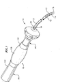
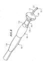
- the catheter comprises an elongated catheter body 12 having proximal and distal ends, a tip section 14 at the distal end of the catheter body, and a control handle 16 at the proximal end of the catheter body.
- the catheter body 12 comprises an elongated tubular construction having a single, axial or central lumen 18 .
- the catheter body 12 can have additional lumens if desired, although a single central lumen 18 is presently preferred.
- the catheter body is flexible, i.e., bendable, but substantially non-compressible along its length.
- the catheter body 12 can be of any suitable construction and made of any suitable material.
- a presently preferred construction comprises an outer wall 20 made of polyurethane or PEBAXTM.
- the outer wall 20 comprises an imbedded braided mesh of stainless steel or the like to increase torsional stiffness of the catheter body 12 so that, when the control handle 16 is rotated, the tip section 14 will rotate in a corresponding manner.
- the outer diameter of the catheter body 12 is not critical, but is preferably no more than about 8 french, more preferably about 7 french.
- the thickness of the outer wall 20 is not critical, but is thin enough so that the central lumen 18 can accommodate at least two puller wires and one or more electrode lead wires.
- the inner surface of the outer wall 20 is lined with a stiffening tube 22, which can be made of any suitable material, such as polyimide or nylon.
- the stiffening tube 22, along with the braided outer wall 20, provides improved torsional stability while at the same time minimizing the wall thickness of the catheter, thus maximizing the diameter of the central lumen 18.
- the outer diameter of the stiffening tube 22 is about the same as or slightly smaller than the inner diameter of the outer wall 20.
- the tip section 14 comprises a short section of tubing 24 having an axial lumen 26 and first and second off-axis lumens 28 and 30.
- the tubing 24 is made of a suitable non-toxic material that is preferably more flexible than the catheter body 12.
- a presently preferred material for the tubing 24 is braided polyurethane, i.e., polyurethane with an embedded mesh of braided stainless steel or the like.
- the outer diameter of the tip section 14, like that of the catheter body 12, is preferably no greater than about 8 french, more preferably about 7 french.
- the tip section 14 can have only two lumens, both off-axis lumens. A description of such a design is provided in U.S. Patent No. 6,210,407, entitled "Bidirectional Electrode Catheter”.
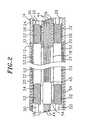
- FIG. 2 A preferred means for attaching the catheter body 12 to the tip section 14 is illustrated in FIG. 2.
- the proximal end of the tip section 14 comprises an outer circumferential notch 32 that receives the inner surface of the outer wall 20 of the catheter body 12.
- the tip section 14 and catheter body 12 are attached by glue or the like.
- the stiffening tube 22 is inserted into the catheter body.
- the distal end of the stiffening tube 22 is fixedly attached near the distal end of the catheter body 12 by forming a glue joint (not shown) with polyurethane glue or the like.
- a small distance e.g., about 3 mm, is provided between the distal end of the catheter body 12 and the distal end of the stiffening tube 22 to permit room for the catheter body 12 to receive the notch 32 of the tip section 14 .
- a force is applied to the proximal end of the stiffening tube 22 , and, when the stiffening tube is under compression, a first glue joint (not shown) is made between the stiffening tube 22 and the outer wall 20 by a fast drying glue joint, e.g., Super GlueTM. Thereafter a second glue joint (not shown) is formed between the proximal ends of the stiffening tube 22 and outer wall 20 using a slower drying but stronger glue, e.g., polyurethane.
- a fast drying glue joint e.g., Super GlueTM
- a spacer 23 can be located within the catheter body between the distal end of the stiffening tube and the proximal end of the tip section.
- the spacer 23 provides a transition in flexibility at the junction of the catheter body and tip section, which allows this junction to bend smoothly without folding or kinking.
- a catheter having such a spacer is described in U.S. Patent No. US-A-5 964 757 entitled "Steerable Direct Myocardial Revascularization Catheter".
- a tip electrode 38 At the distal end of the tip section 14 is a tip electrode 38 .
- the tip electrode 38 has a diameter about the same as the outer diameter of the tubing 24 .
- the tip electrode 38 is attached to the tubing 24 by creating a notch 40 in the proximal end of the tip electrode, placing the proximal end of the tip electrode on the distal end of the tubing, and filling the notch with glue.
- ring electrodes 42 are mounted on the tubing 24 proximal to the tip electrode 38 .
- Each ring electrode 42 is slid over the tubing 24 and fixed in place by glue or the like. It is understood that the presence, number and position of ring electrodes may vary as desired. Similarly, a tip electrode may be excluded if desired.
- the tip electrode 38 and ring electrodes 42 Can be made of any suitable material, and are preferably machined from platinum-iridium bar (90% platinum/10% iridium).
- the tip electrode 38 and ring electrodes 42 are each connected to a separate electrode lead wire 44 .
- the lead wires 44 extend through the axial lumen 26 of the tip section 14 , the central lumen 18 of the catheter body 12 , and the control handle 16 , and terminate at their proximal end in an input jack (not shown) that may be plugged into an appropriate monitor (not shown).
- an input jack not shown
- the portion of the lead wires 44 extending through the central lumen 18 of the catheter body 12 , control handle 16 and proximal end of the tip section 14 can be enclosed within a protective sheath (not shown), which can be made of any suitable material, preferably polyimide.
- the lead wires 44 are attached to the tip electrode 38 and ring electrodes 42 by any suitable conventional technique. Connection of a lead wire 44 to the tip electrode 38 is accomplished, for example, by welding the lead wire 44 into a hole 46 in the tip electrode.
- Connection of a lead wire 44 to a ring electrode 42 is preferably accomplished by first making a small hole through the tubing 24 .
- a hole can be created, for example, by inserting a needle through the tubing 24 and heating the needle sufficiently to form a permanent hole (not shown).
- a lead wire 44 is then drawn through the hole by using a microhook or the like.
- the ends of the lead wires 44 are then stripped of any coating and soldered or welded to the underside of the ring electrode 42 , which is then slid into position over the hole and fixed in place with polyurethane glue or the like.
- Two puller wires 50 extend through the catheter body 12 .
- the puller wires 50 are anchored at their proximal ends to the control handle 16 and at their distal ends to the tip section 14 .
- the puller wires 50 are made of any suitable metal, such as stainless steel or Nitinol, and are preferably coated with TeflonTM or the like. The coating imparts lubricity to the puller wires 50 .
- the puller wires 50 preferably each have a diameter ranging from about 152 ⁇ m (0.006 inch) to about 254 ⁇ m (0.010) inch.
- Two compression coils 52 are provided in the catheter body 12 , each in surrounding relation to a corresponding puller wire 50 .
- the compression coils 52 extend from the proximal end of the catheter body 12 to the proximal end of the tip section 14 .
- the compression coils 52 are made of any suitable metal, preferably stainless steel.
- the compression coils 52 are tightly wound on themselves to provide flexibility, i.e., bending, but to resist compression.
- the inner diameter of each compression coil 52 is preferably slightly larger than the diameter of the corresponding puller wire 50 .
- the TeflonTM coating on the puller wires 50 allows them to slide freely within the compression coils 52 .
- the outer surface of each compression coil 52 is covered by a flexible, non-conductive sheath 53 , e.g., made of polyimide tubing, to prevent contact between the compression coils 52 and the lead wires 44 .
- Each compression coil 52 is anchored at its proximal end to the proximal end of the stiffening tube 22 in the catheter body 12 by glue joint 54 and at its distal end to the tip section 14 by glue joint 56 .
- Both glue joints 54 and 56 preferably comprise polyurethane glue or the like.
- the glue may be applied through a hole (not shown) made between the outer surface of the catheter body 12 and the central lumen 18 . Such a hole may be formed, for example, by a needle or the like that punctures the outer wall 20 of the catheter body 12 and the stiffening tube 22 , which is heated sufficiently to form a permanent hole.
- the glue is then introduced through the hole to the outer surface of the compression coil 52 and wicks around the outer circumference to form a glue joint about the entire circumference of the compress coil.
- a short section of plastic tubing 45 is provided around the lead wires 44 near the glue joint 54 to provide the lead wires with flexibility within the glue joint.
- the distal ends of the compression coils 52 can be anchored in the distal end of the catheter body 12 .
- the puller wires 50 extend into the first off-axis lumen 28 and second off-axis lumen 30 of the tip section 14 .
- Each puller wire 50 extends through a plastic, preferably TeflonTM, sheath 55 , which prevents that puller wire from cutting into the wall of the tip section 14 when the tip section is deflected.
- Each puller wire 50 is anchored at its distal end to the tip electrode 38 within a blind hole 58 .
- the puller wires 50 are anchored in opposite sides of the tip electrode 38 so that the tip section can deflect in two opposing directions, as described in more detail below.
- a preferred method for anchoring each puller wire 50 in the tip electrode 38 is by crimping metal tubing (not shown) to the distal end of each puller wire 50 and soldering the metal tubing inside the blind hole 58 .
- Other means known to those skilled in the art for anchoring the puller wires 50 in the tip electrode 38 could also be used.
- one or both of the puller wires 50 can be anchored to the sides of the tip section 14 .
- the distal ends of the puller wires 50 comprise T-bar anchors 61 as described above and are preferably anchored by glue 62 in notches 63 in the side wall of the flexible tubing 24 as shown in FIG. 4 and as described in U.S. Patent No. 6,064,905 (entitled “Multi-Element Tip Electrode Mapping Catheter”).
- the puller wires 50 can both be anchored to the same side of the tip section with one puller wire anchored proximal the other puller wire.
- the tip section could form a U-shaped curve.
- Other puller wire anchoring arrangements could also be provided to permit the tip section to deflect to form two different curves.
- the control handle 16 illustrated in FIGs. 5 to 7, comprises a handle housing 64 and a piston 66, both having proximal and distal ends.
- This piston 66 moves both longitudinally and rotatably with respect to the handle housing 64 .
- the housing 64 and piston 66 preferably both comprise a rigid plastic, such as Delrin®, an acetal homopolymer commercially available from DuPont.
- the proximal end of the piston 66 is slidably and rotatably mounted within a piston chamber in the distal end of the handle housing 64 .
- the distal end of the piston 66 is fixedly attached to the proximal end of the catheter body 12 .
- the piston 66 has a thumb control 68 at its distal end.
- the handle housing 64 comprises a proximal section 130 and a distal section 132 .
- the distal end of the proximal section 130 of the housing 64 comprises a circumferential notch 134 into which the proximal end of the distal section 132 fits.
- the proximal section 130 and the distal section 132 can be press-fit together.
- the handle housing 64 can be formed of a single piece of plastic instead of proximal and distal sections.
- a grip piece 136 made of rubber or the like to provide comfort to the user.
- the piston has first and second longitudinal grooves 70 and 72 , each of the grooves having a proximal and distal end.
- the distal ends of the longitudinal grooves 70 and 72 are connected by a circumferential groove 74 .
- the longitudinal grooves 70 and 72 are deeper than the circumferential groove 74 , creating a step 78 at the distal ends of the longitudinal grooves under the circumferential groove.
- a puller wire anchor 76 is slidably mounted within each longitudinal groove 70 and 72 .
- the two puller wire anchors 76 each comprise a short metal rod, preferably made of aluminum or stainless steel.
- the step 78 at the distal ends of the longitudinal grooves 70 and 72 prevents the puller wire anchors 76 from sliding into the circumferential groove 74 .
- each puller wire 50 is fixedly attached to a corresponding puller wire anchor 76 by any suitable means, for example, by soldering the puller wire into a hole in the metal rod.
- the rod can have a small hole at its distal end and a larger hole at its proximal end.
- a piece of hypodermic stock or the like is crimped on the proximal end of the puller wire. The hypodermic stock fits into the larger hole in the rod, but not the smaller hole, preventing the puller wire from being pulled distally out of the rod.
- An internal passage 77 extends within the piston 66 through which the puller wires 50 and lead wires (not shown) extend.
- Two generally diagonally small holes 80 are provided in the step 78 , each in general alignment with one of the longitudinal grooves 70 and 72 and in communication with the internal passage 77 .
- the puller wires 50 extend through the holes 80 for connection to the puller wire anchors 76 .
- a set screw 82 extends radially inwardly from the handle housing 64 into the circumferential groove 74 .
- the piston can be rotated between first and second positions relative to the housing. Rotation of the piston 66 relative to the housing 64 results in movement of the circumferential groove 74 relative to the set screw 82 .
- the set screw 82 is aligned with the first longitudinal groove 70 , as shown in FIG. 7.
- the set screw 82 is aligned with the second longitudinal groove 72 .
- the set screw 82 could be replaced by a pin, ring or the like (for example, as described below) that is held stationary relative to the piston 66 , whether or not fixedly attached to the handle housing 64 .
- Distal movement of the piston 66 relative to the handle housing 64 results in longitudinal movement of the piston relative to the stationary set screw 82 .
- the set screw 82 is in its first position (i.e., aligned with the first longitudinal groove 70 ) and the piston 66 is moved distally relative to the handle housing 64 , the first longitudinal groove 70 (along with the piston) slides distally relative to the set screw, which extends radially inwardly into the first longitudinal groove.
- distal movement of the puller wire anchor 76a in the first longitudinal groove 70 is blocked by the stationary set screw 82 .
- the puller wire 50 connected to the blocked puller wire anchor 76a is also held stationary relative to the distally moving piston 66 and catheter body 12 , which is fixedly attached to the piston. This results in deflection of the tip section 14 in the direction of the off-axis lumen 28 or 30 into which that puller wire 50 extends.
- the set screw 82 blocks movement of the puller wire anchor 76b , which remains stationary relative to the distally-moving piston.
- the puller wire 50 connected to the puller wire anchor 76b is held stationary relative to the distally moving piston 66 and catheter body 12 , thus deflecting the tip section 14 in the direction of the off-axis lumen 28 or 30 into which that puller wire extends.
- This design permits deflection of the tip section 14 to form two different curves, and preferably to deflect in two different directions, while preventing simultaneous movement of the puller wires 50 .
- the above-described design could be used with a unidirectional catheter, i.e., having only a single puller wire. If only a single puller wire is included in the catheter, only a single longitudinal groove is provided in the piston. A circumferential groove is not necessary, but the set screw (or other pin) must extend into the longitudinal groove distal the puller wire anchor.
- the handle 16 comprises a handle housing 64 and a piston assembly 65 , both having proximal and distal ends.
- the piston assembly 65 comprises a piston 66 at its proximal end and a thumb control 68 at its distal end, as well as additional components described in more detail below.
- the proximal end of the piston assembly 65 is slidably mounted within a piston chamber in the distal end of the handle housing 64 .
- the distal end of the piston assembly 65 is fixedly attached to the proximal end of the catheter body 12 .
- the piston 66 comprises an internal passage 77 extending therethrough through which the puller wires 50 and lead wires (not shown) extend.
- the handle housing 64 comprises a proximal section 130 and a distal section 132 .
- the distal end of the proximal section 130 of the housing 64 comprises a circumferential notch 134 into which the proximal end of the distal section 132 fits.
- the proximal section 130 and the distal section 132 can be press-fit together.
- a grip piece 136 made of rubber or the like to provide comfort to the user.
- the piston chamber has a first inner diameter 138 , a second inner diameter 140 , and a third inner diameter 142 .
- the first inner diameter 138 is proximal the second inner diameter 140 , both of which are distal the third inner diameter 142 .
- the second inner diameter 140 is smaller than the first inner diameter 138 , but is only slightly larger than the outer diameter of the piston 66 .
- the third inner diameter 142 is smaller than the first inner diameter 138 and preferably similar in size to the second inner diameter 140 .
- FIG. 11 shows the proximal portion of the piston assembly 65 , which comprises a proximal section 84 , a distal section 86 , and a circumferential recess 85 between the proximal section and distal section.
- the proximal section 84 comprises a series of longitudinal grooves, including deep longitudinal grooves 88 and shallow longitudinal grooves 90 , about its entire circumference.
- the depicted embodiment has two deep longitudinal grooves 88 and four shallow longitudinal grooves 90 , as shown best in FIG. 13.
- the two deep longitudinal grooves 88 are adjacent to each other.
- the longitudinal grooves 88 and 90 are separated from one another by dividing walls 92 .
- Each dividing wall 92 has an angled distal end 94 .
- a puller wire anchor 76 is slidably disposed within each deep longitudinal groove 88 .
- the distal ends of the deep longitudinal grooves 88 terminate in a vertical wall 79 .
- Each vertical wall 79 contains a small hole (not shown).
- Two puller wires 50 extend through the internal passage 77 and through one of the small holes so that the puller wires can be attached to the puller wire anchors 76 as described above.
- the distal section 86 which has proximal and distal ends, is spaced apart from the proximal section 84 by the circumferential recess 85 .
- the proximal end of the distal section 86 comprises a plurality of tooth-shaped notches 96 .
- the number of tooth-shaped notches 96 is the same as the number of dividing walls 92 , which in the depicted embodiment is six.
- the piston assembly 65 further comprises a ring 98 rotatably mounted on the piston 66 .
- the ring 98 is preferably made of a generally rigid plastic, such as Delrin®, acrylonitrile-butadiene-styrene resin, polyester, polyethylene or the like.
- the ring 98 has a proximal end 104 and a distal end 106 .
- the outer diameter of the ring 98 is slightly greater than the outer diameter of the distal portion of the piston 66 .
- the inner diameter of the ring 98 is slightly greater than the outer diameter of the circumferential recess 85 .
- the ring 98 has a plurality of projections 110 that extend radially inwardly into the circumferential recess 85 and that are sized to be received by the longitudinal grooves 88 and 90 .
- FIG. 12 depicts the ring 98 slid proximally so that it is positioned over the longitudinal grooves 88 and 90 with the projections 110 extending inwardly into the grooves.
- the projections 110 are spaced apart so that they can be aligned with every other longitudinal groove 88 and 90 .
- three projections 110 are provided on the ring 98 .
- the distal end 106 of the ring 98 comprises a plurality of teeth 108 spaced apart to be aligned with every other notch 96 . Accordingly, the number of teeth 108 is equal to half the number of notches 96 . In the depicted embodiment the ring 98 contains three teeth 108 .
- the teeth 108 have a thickness so they project inward, preferably to about the same depth as the projections 110 .
- the piston assembly 65 further comprises a cylindrical sleeve 114 disposed about the distal section 86 of the piston 66 .
- the sleeve 114 which has proximal and distal ends, is preferably made of a generally rigid plastic, such as Delrin®, polycarbonate or the like.
- the proximal end of the sleeve 114 contains three tooth-shaped notches 116 around its circumference that generally correspond in size, shape and position to the three teeth 108 on the distal end 106 of the ring 98 .
- the proximal end of the sleeve 114 fits against the top or outer portion of the ring 98 , and the projections 110 on the ring fit against the notches 96 on the proximal end of the distal section 86 of the piston. If the number of teeth 108 on the ring 98 is increased or decreased, the number of tooth-shaped notches 116 on the sleeve 114 is correspondingly increased or decreased.
- the ring 98 and sleeve 114 rotate together about the piston 66 due to the interlocking between the tooth-shaped notches 116 on the sleeve and the teeth 108 on the ring.
- the piston 66 comprises a circumferential groove 57 into which an o-ring (not shown) fits to seal the space between the piston and the sleeve.
- the ring 98 and sleeve 114 have approximately the same outer diameter, which is smaller than the first inner diameter 138 of the piston chamber but larger than the second and third diameters 140 and 142 of the piston chamber. Due to the difference between the first inner diameter 138 and the second inner diameter 140 , the handle housing 64 comprises a distal cylindrical flange 139 at the distal end of the piston chamber to prevent distal movement of the sleeve 114 (and thus the ring 98 ) relative to the housing, which also prevents distal movement of the sleeve out of the piston chamber.
- the handle housing 64 comprises a proximal cylindrical flange 141 midway through the piston chamber to prevent proximal movement of the ring 98 (and thus the sleeve 114 ) relative to the housing.
- Movement of the piston 66 distally relative to the handle housing 64 e.g., by pushing on the thumb rest 68 , results in the piston sliding distally relative to the sleeve 114 and ring 98 so that the ring is positioned over the longitudinal grooves 88 and 90 rather than the circumferential recess 85 , as shown in FIG. 12.
- the projections 110 on the ring 98 are received by every other of the longitudinal grooves 88 and 90 . In the arrangement described, one projection 110 will be received by one of the deep longitudinal grooves 88 , but not the other.
- the projection 110 extending into the deep longitudinal groove 88 engages and blocks the puller wire anchor 76 in that groove, holding it and its associated puller wire 50 stationary relative to the distally-moving piston 66 .
- Such movement results in deflection of the tip section 14 in the direction of the off-axis lumen into which the distal end of the puller wire 50 extends.
- the ring 98 can be engaged by the handle housing 64 in any other manner such that the distal or proximal movement of the piston 66 relative to the housing causes the ring to remain longitudinally stationary relative to the distally or proximally moving piston, but still rotatable on the piston.
- the projections 110 To engage the puller wire anchor 76b in the adjacent deep longitudinal groove 88 , and thus enable deflection of the tip section in the direction of the off-axis lumen of the other puller wire 50 , the projections 110 must be moved into alignment with the adjacent longitudinal grooves. To accomplish this, the piston 66 is moved proximally relative to the handle housing 64 until the teeth 108 on the ring 98 engage the tooth shaped notches 96 on the proximal end of the distal section of the piston 86 . Because of the shapes of the teeth 108 and the notches 96 , the ring 98 rotates as the teeth 108 engage the notches 96 . The amount of rotation results in the projections 110 on the ring 98 being aligned with the adjacent longitudinal grooves 88 .
- the projections 110 are received by the adjacent longitudinal grooves 88 and 90 .
- the projection 110 received by the deep longitudinal groove 88 engages and blocks distal movement of the puller wire anchor 76b in that groove, holding it stationary relative to the distally-moving piston 66 in a manner similar to that described above.
- This also holds the puller wire 50 anchored to that puller wire anchor 76b stationary relative to the distally-moving piston 66 and catheter body 12 , resulting in deflection of the tip section 14 in the direction of the off-axis lumen into which that puller wire extends.
- the piston 66 When it is desired to again deflect the tip section 14 in the direction of the puller wire 50 in the first deep longitudinal groove 88 , the piston 66 is again moved proximally until the teeth 108 on the ring 98 engage the tooth shaped notches 96 . The ring 98 again rotates relative to the piston 66 as the teeth 108 of the ring engage the notches 96 . A different projection 110 then comes into alignment with the first deep longitudinal groove 88.
- an identification mechanism is provided so that the physician can readily ascertain which puller wire 50 is engaged.
- a preferred mechanism comprises three holes 118 spaced 120° apart around the circumference of the sleeve 114 near its distal end, as shown in FIG. 10.
- the sleeve 114 is a different color than the piston 66 .
- the distal section 132 of the handle housing 64 has a hole 120 generally positioned in line with the holes 118 so that one of the holes 118 can be aligned with the hole 120 .
- the sleeve 114 rotates relative to the piston 66 and housing 64 , it is positioned in one of six positions relative to the piston and housing.
- one of the holes 118 is aligned with the hole 120 so that the user can see the piston 66 through the hole 120 .
- These three positions correspond to one of the puller wires being blocked.
- the user sees the sleeve 114 through the hole 120 .
- a set screw (not shown) can be provided to assure that the piston 66 is not separated from the handle housing 64 .
- the set screw could extend through the handle housing 64 and into one of the shallow longitudinal grooves 90 of the piston 66 .
- Other means for assuring that the piston is not separated from the handle housing can also be used.
- the ring 98 and sleeve 114 could be replaced with a single piece that performs all of the functions of the ring and sleeve described above.
- the sleeve 114 could be removed altogether. With such a design, the length of the distal section 130 of the handle housing 64 having the first inner diameter 138 would be decreased so that the second inner diameter 140 is much closer to the ring 98 .
- the above-described handle designs can be used with a multidirectional catheter having more than two puller wires.
- the number of longitudinal grooves (and puller wire anchors) would be increased to correspond to the number of puller wires.
- the number of deep longitudinal grooves (and puller wire anchors) would be increased to correspond to the number of puller wires.
- the number of protrusions on the ring would be modified so that only one protrusion extends into one of the deep longitudinal grooves.
- the protrusions on the ring would be aligned with every third longitudinal groove.
- the piston would be modified to have four deep longitudinal grooves and four shallow longitudinal grooves, and the protrusions on the ring would be aligned with every fourth longitudinal groove.
- the deep longitudinal grooves need not be adjacent each other.
- all of the longitudinal grooves can be of the same depth, similar to the deep longitudinal grooves.
- the ring can contain more or less teeth as desired, but preferably a number equal to the number of protrusions on the ring for simplicity in manufacturing the ring.
Landscapes
- Health & Medical Sciences (AREA)
- Life Sciences & Earth Sciences (AREA)
- Engineering & Computer Science (AREA)
- Heart & Thoracic Surgery (AREA)
- Animal Behavior & Ethology (AREA)
- Pulmonology (AREA)
- Anesthesiology (AREA)
- Biomedical Technology (AREA)
- Veterinary Medicine (AREA)
- Hematology (AREA)
- Biophysics (AREA)
- General Health & Medical Sciences (AREA)
- Public Health (AREA)
- Mechanical Engineering (AREA)
- Media Introduction/Drainage Providing Device (AREA)
- Electrotherapy Devices (AREA)
- Surgical Instruments (AREA)
- Endoscopes (AREA)
Claims (10)
- In mehrere Richtungen steuerbarer Katheter (10) umfassend:wobei eine distale Bewegung des Kolbens (66) relativ zu dem Griffgehäuse (64) dazu führt, dass sich ein Fortsatz (110) auf dem Ring (98) in eine der Längsrillen (88, 90) erstreckt, um dadurch eine Längsbewegung des Zugdrahtankers (76) in der Rille (88, 90) relativ zum Griffgehäuse (64) zu verhindern, wodurch eine Ablenkung des Spitzenbereiches (14) in die Richtung des Hohlraumes (28, 30) bedingt wird, in den sich der Zugdraht (50), der mit dem Anker (76) verbunden ist, erstreckt, und wobei weiter eine proximale Bewegung des Kolbens (66) relativ zu dem Griffgehäuse (64) eine Drehung des Ringes (98) bedingt, wodurch der gleiche Fortsatz (110) mit einer anderen Längsrille (88, 90) ausgerichtet wird, um dadurch eine Längsbewegung des Zugdrahtankers (76) in der Rille (88, 90) relativ zu dem Griffgehäuse (64) zu verhindern, wodurch eine Ablenkung des Spitzenbereiches (14) in die Richtung des Hohlraumes (28, 30) bedingt wird, in den sich der mit dem Anker (76) verbundene Zugdraht (50) erstreckt.einen Katheterkörper (12) mit einer röhrenförmigen Wand (20), einem proximalen und einem distalen Ende und wenigstens einem Hohlraum (18), der sich dadurch hindurch erstreckt;einen Spitzenabschnitt (14), der eine flexible Röhre (24) umfasst mit einem proximalen und einem distalen Ende und wenigstens einem Hohlraum (26, 28, 30), der sich dadurch hindurch erstreckt, wobei das proximale Ende des Spitzenabschnittes (14) fest an dem distalen Ende des Katheterkörpers (12) angebracht ist;einen Steuergriff (16) mit einem proximalen und einem distalen Ende, der an seinem distalen Ende an dem proximalen Ende des Katheterkörpers (12) befestigt ist, umfassend:erste und zweite Zugdrähte (50) mit proximalen und distalen Enden, wobei sich ein jeder Zugdraht (50) von dem Steuergriff (16) durch einen Hohlraum (77) in den Katheterkörper und in einen Hohlraum (28, 30) in dem Spitzenbereich (14) erstreckt, wobei das proximale Ende eines jeden Zugdrahtes (50) fest an einem getrennten Zugdrahtanker (76) in dem Steuergriff angebracht ist;ein erstes Mittel zum Ablenken des Spitzenbereiches (14), um eine erste Kurve in Reaktion auf eine proximale Bewegung des ersten Zugdrahtes (50) relativ zum Katheterkörper (12) auszubilden; undein zweites Mittel zum Ablenken des Spitzenbereiches, um eine zweite Kurve in Reaktion auf eine proximale Bewegung des zweiten Zugdrahtes (50) relativ zu dem Katheterkörper (12) auszubilden, die von der ersten Kurve verschieden ist;ein Gehäuse (64) mit einem proximalen Ende und einem distalen Ende und einer Kolbenkammer, die sich dadurch hindurch erstreckt, wobei die Kolbenkammer ein proximales und ein distales Ende aufweist; undeine Kolbenanordnung (65) mit einem proximalen und distalen Bereich (84, 86), die in der Kolbenkammer des Gehäuses (64) verschiebbar befestigt und in Längsrichtung zwischen proximalen und distalen Positionen beweglich ist, wobei der distale Abschnitt (86) der Kolbenanordnung (65) fest an dem proximalen Ende des Katheterkörpers (12) angebracht ist, und dadurch gekennzeichnet ist, dass der distale Bereich (86) ein proximales und ein distales Ende aufweist und eine Vielzahl von Schlitzen (96) an seinem proximalen Ende umfasst;der proximale Bereich (84) eine Vielzahl von Längsrillen (88, 90) um seinen gesamten Umfang herum aufweist, die durch Trennwände (92) mit winkligen distalen Enden (94) getrennt sind;eine Umfangsaussparung (85) zwischen dem proximalen Bereich (84) und dem distalen Bereich (86);einen Ring (98) mit einem proximalen und einem distalen Ende (104, 106) und drehbar an der Kolbenanordnung (65) befestigt, wobei der Ring (98) eine Vielzahl von Fortsätzen (110) aufweist, die sich radial nach innen in die Umfangsaussparung (85) erstrecken und die in der Lage sind, von den Längsrillen (88, 90) aufgenommen zu werden, wobei die Anzahl der Fortsätze (110) geringer ist als die Anzahl der Längsrillen (88, 90), und weiter eine Vielzahl von Zähnen (108) an seinem distalen Ende (106) aufweist, die in der Lage sind, durch die Schlitze (96) aufgenommen zu werden; underste und zweite Zugdrahtanker (76), wobei ein jeder Zugdrahtanker (76) verschiebbar innerhalb einer entsprechenden Längsrille (88) angeordnet ist;
- Katheter nach Anspruch 1 mit mehr als zwei Zugdrahtankern und mehr als zwei Zugdrähten.
- Katheter nach Anspruch 1, wobei die Anzahl der Fortsätze auf dem Ring gleich der Hälfte der Anzahl der Längsrillen ist.
- Katheter nach Anspruch 1, wobei der Ring drei Fortsätze und der distale Bereich der Kolbenanordnung sechs Längsrillen aufweist.
- Katheter nach Anspruch 1, wobei das erste und zweite Mittel zum Bedingen einer Ablenkung des Spitzenbereiches Anker umfassen, die die Zugdrähte an der Seite des Spitzenbereiches verankern.
- Katheter nach Anspruch 1, weiter umfassend eine Spitzenelektrode (38).
- Katheter nach Anspruch 6, wobei das Mittel zum Bedingen der Ablenkung des Spitzenbereiches Lötzinn umfasst, der den Zugdraht an der Spitzenelektrode verankert.
- Katheter nach Anspruch 1, weiter umfassend Mittel zum Halten des Rings in der Kolbenkammer.
- Katheter nach Anspruch 8, wobei das Haltemittel einen zylindrischen Flansch (139) nahe dem distalen Ende der Kolbenkammer umfasst.
- Katheter nach Anspruch 1 umfassend zwei Zugdrähte, die sich in gegenüberliegende, außerhalb der Achse gelegene Hohlräume in dem Spitzenbereich erstrecken.
Applications Claiming Priority (2)
| Application Number | Priority Date | Filing Date | Title |
|---|---|---|---|
| US273679 | 1999-03-22 | ||
| US09/273,679 US6183435B1 (en) | 1999-03-22 | 1999-03-22 | Multi-directional steerable catheters and control handles |
Publications (2)
| Publication Number | Publication Date |
|---|---|
| EP1038546A1 EP1038546A1 (de) | 2000-09-27 |
| EP1038546B1 true EP1038546B1 (de) | 2005-09-28 |
Family
ID=23044959
Family Applications (1)
| Application Number | Title | Priority Date | Filing Date |
|---|---|---|---|
| EP00302299A Expired - Lifetime EP1038546B1 (de) | 1999-03-22 | 2000-03-21 | In mehrere Richtungen lenkbarer Katheter mit Steuergriff |
Country Status (5)
| Country | Link |
|---|---|
| US (1) | US6183435B1 (de) |
| EP (1) | EP1038546B1 (de) |
| JP (1) | JP2000312720A (de) |
| AT (1) | ATE305323T1 (de) |
| DE (1) | DE60022808T2 (de) |
Cited By (1)
| Publication number | Priority date | Publication date | Assignee | Title |
|---|---|---|---|---|
| CN102258823A (zh) * | 2010-04-21 | 2011-11-30 | 日本来富恩株式会社 | 导管 |
Families Citing this family (152)
| Publication number | Priority date | Publication date | Assignee | Title |
|---|---|---|---|---|
| US6482221B1 (en) | 2000-08-21 | 2002-11-19 | Counter Clockwise, Inc. | Manipulatable delivery catheter for occlusive devices (II) |
| US6726700B1 (en) | 2000-08-21 | 2004-04-27 | Counter Clockwise, Inc. | Manipulatable delivery catheter for occlusive devices |
| US6979312B2 (en) * | 2001-04-12 | 2005-12-27 | Biotran Corporation, Inc. | Steerable sheath catheters |
| US6913594B2 (en) | 2001-12-31 | 2005-07-05 | Biosense Webster, Inc. | Dual-function catheter handle |
| US6733499B2 (en) | 2002-02-28 | 2004-05-11 | Biosense Webster, Inc. | Catheter having circular ablation assembly |
| US7192415B2 (en) * | 2002-03-22 | 2007-03-20 | Scimed Life Systems, Inc. | Drainage catheter with visual indicator and/or lock system |
| US7588568B2 (en) * | 2002-07-19 | 2009-09-15 | Biosense Webster, Inc. | Atrial ablation catheter and method for treating atrial fibrillation |
| US7004937B2 (en) * | 2002-07-31 | 2006-02-28 | Cryocor, Inc. | Wire reinforced articulation segment |
| US20040034365A1 (en) * | 2002-08-16 | 2004-02-19 | Lentz David J. | Catheter having articulation system |
| US7819866B2 (en) | 2003-01-21 | 2010-10-26 | St. Jude Medical, Atrial Fibrillation Division, Inc. | Ablation catheter and electrode |
| US7163537B2 (en) * | 2003-06-02 | 2007-01-16 | Biosense Webster, Inc. | Enhanced ablation and mapping catheter and method for treating atrial fibrillation |
| US7101362B2 (en) * | 2003-07-02 | 2006-09-05 | St. Jude Medical, Atrial Fibrillation Division, Inc. | Steerable and shapable catheter employing fluid force |
| US7235070B2 (en) * | 2003-07-02 | 2007-06-26 | St. Jude Medical, Atrial Fibrillation Division, Inc. | Ablation fluid manifold for ablation catheter |
| US7678104B2 (en) * | 2003-07-17 | 2010-03-16 | Biosense Webster, Inc. | Ultrasound ablation catheter and method for its use |
| US10182734B2 (en) * | 2003-07-18 | 2019-01-22 | Biosense Webster, Inc. | Enhanced ablation and mapping catheter and method for treating atrial fibrillation |
| US6926711B2 (en) * | 2003-07-30 | 2005-08-09 | Cryocor, Inc. | Articulating catheter for cryoablation with reduced diameter section |
| DE10337580B4 (de) * | 2003-08-16 | 2009-07-02 | Dr. Osypka Gmbh | Katheter mit elastisch biegbarem oder lenkbarem Ende |
| US20050119644A1 (en) * | 2003-12-01 | 2005-06-02 | Koerner Richard J. | Articulating catheter tip with wedge-cuts |
| US7637903B2 (en) * | 2004-02-09 | 2009-12-29 | Cryocor, Inc. | Catheter articulation segment with alternating cuts |
| US20050177131A1 (en) * | 2004-02-09 | 2005-08-11 | Lentz David J. | Catheter articulation segment with alternating cuts |
| US8007495B2 (en) * | 2004-03-31 | 2011-08-30 | Biosense Webster, Inc. | Catheter for circumferential ablation at or near a pulmonary vein |
| US20050283179A1 (en) * | 2004-06-17 | 2005-12-22 | Lentz David J | Introducer sheath |
| US7285108B2 (en) * | 2004-06-24 | 2007-10-23 | Cryocor, Inc. | Active system for deflecting a distal portion of a catheter into a hoop configuration |
| US7374553B2 (en) * | 2004-06-24 | 2008-05-20 | Cryocor, Inc. | System for bi-directionally controlling the cryo-tip of a cryoablation catheter |
| US7357797B2 (en) * | 2004-06-30 | 2008-04-15 | Cryocor, Inc. | System and method for varying return pressure to control tip temperature of a cryoablation catheter |
| US7717875B2 (en) | 2004-07-20 | 2010-05-18 | St. Jude Medical, Atrial Fibrillation Division, Inc. | Steerable catheter with hydraulic or pneumatic actuator |
| US20060047245A1 (en) * | 2004-08-24 | 2006-03-02 | Ruchir Sehra | Catheter control unit |
| US8583260B2 (en) | 2004-12-28 | 2013-11-12 | St. Jude Medical, Atrial Fibrillation Division, Inc. | Long travel steerable catheter actuator |
| US7691095B2 (en) | 2004-12-28 | 2010-04-06 | St. Jude Medical, Atrial Fibrillation Division, Inc. | Bi-directional steerable catheter control handle |
| US8858495B2 (en) | 2004-12-28 | 2014-10-14 | St. Jude Medical, Atrial Fibrillation Division, Inc. | Five degree of freedom ultrasound catheter and catheter control handle |
| US7591784B2 (en) | 2005-04-26 | 2009-09-22 | St. Jude Medical, Atrial Fibrillation Division, Inc. | Bi-directional handle for a catheter |
| US7819868B2 (en) * | 2005-06-21 | 2010-10-26 | St. Jude Medical, Atrial Fibrilation Division, Inc. | Ablation catheter with fluid distribution structures |
| US8777929B2 (en) | 2005-06-28 | 2014-07-15 | St. Jude Medical, Atrial Fibrillation Division, Inc. | Auto lock for catheter handle |
| US7465288B2 (en) * | 2005-06-28 | 2008-12-16 | St. Jude Medical, Atrial Fibrillation Division, Inc. | Actuation handle for a catheter |
| JP2007018615A (ja) * | 2005-07-08 | 2007-01-25 | Sony Corp | 記憶装置及び半導体装置 |
| US20070060997A1 (en) * | 2005-09-15 | 2007-03-15 | Jan De Boer | Multi-lumen steerable catheter |
| US9445784B2 (en) | 2005-09-22 | 2016-09-20 | Boston Scientific Scimed, Inc | Intravascular ultrasound catheter |
| JP4905647B2 (ja) * | 2006-02-14 | 2012-03-28 | 朝日インテック株式会社 | 医療用具 |
| EP2604309A1 (de) | 2006-05-19 | 2013-06-19 | Boston Scientific Limited | Steuermechanismus für lenkbare medizinische Geräte |
| WO2008031103A2 (en) * | 2006-09-08 | 2008-03-13 | Edwards Lifesciences Corporation | Integrated heart valve delivery system |
| EP2099386A4 (de) * | 2006-10-16 | 2012-11-14 | Scottsdale Medical Devices Inc | Schneidvorrichtung und verfahren zur entnahme von gefässen |
| JP4706008B2 (ja) * | 2006-10-26 | 2011-06-22 | 有限会社リバー精工 | 心臓カテーテル |
| US20220096112A1 (en) | 2007-01-02 | 2022-03-31 | Aquabeam, Llc | Tissue resection with pressure sensing |
| US9232959B2 (en) | 2007-01-02 | 2016-01-12 | Aquabeam, Llc | Multi fluid tissue resection methods and devices |
| US9370640B2 (en) | 2007-09-12 | 2016-06-21 | Novasentis, Inc. | Steerable medical guide wire device |
| US20090131867A1 (en) | 2007-11-16 | 2009-05-21 | Liu Y King | Steerable vertebroplasty system with cavity creation element |
| WO2011066465A1 (en) * | 2009-11-25 | 2011-06-03 | Osseon Therapeutics, Inc. | Steerable and curvable vertebroplasty system with clog-resistant exit ports |
| US20090131950A1 (en) * | 2007-11-16 | 2009-05-21 | Liu Y King | Vertebroplasty method with enhanced control |
| US20090299282A1 (en) * | 2007-11-16 | 2009-12-03 | Osseon Therapeutics, Inc. | Steerable vertebroplasty system with a plurality of cavity creation elements |
| US20090131886A1 (en) | 2007-11-16 | 2009-05-21 | Liu Y King | Steerable vertebroplasty system |
| US9510885B2 (en) | 2007-11-16 | 2016-12-06 | Osseon Llc | Steerable and curvable cavity creation system |
| WO2009073209A1 (en) * | 2007-12-06 | 2009-06-11 | Osseon Therapeutics, Inc. | Vertebroplasty implant with enhanced interfacial shear strength |
| US8137336B2 (en) * | 2008-06-27 | 2012-03-20 | Boston Scientific Scimed, Inc. | Steerable medical device |
| US20090299352A1 (en) * | 2007-12-21 | 2009-12-03 | Boston Scientific Scimed, Inc. | Steerable laser-energy delivery device |
| US7780648B2 (en) | 2007-12-28 | 2010-08-24 | Boston Scientific Scimed, Inc. | Controlling movement of distal portion of medical device |
| EP2676701B1 (de) | 2008-01-07 | 2016-03-30 | Salutaris Medical Devices, Inc. | Vorrichtungen zur minimalinvasiven extraokularen Abgabe von Strahlung an den hintenliegenden Abschnitt des Auges |
| US9873001B2 (en) | 2008-01-07 | 2018-01-23 | Salutaris Medical Devices, Inc. | Methods and devices for minimally-invasive delivery of radiation to the eye |
| US9056201B1 (en) | 2008-01-07 | 2015-06-16 | Salutaris Medical Devices, Inc. | Methods and devices for minimally-invasive delivery of radiation to the eye |
| US8608632B1 (en) | 2009-07-03 | 2013-12-17 | Salutaris Medical Devices, Inc. | Methods and devices for minimally-invasive extraocular delivery of radiation and/or pharmaceutics to the posterior portion of the eye |
| US8602959B1 (en) | 2010-05-21 | 2013-12-10 | Robert Park | Methods and devices for delivery of radiation to the posterior portion of the eye |
| US10022558B1 (en) | 2008-01-07 | 2018-07-17 | Salutaris Medical Devices, Inc. | Methods and devices for minimally-invasive delivery of radiation to the eye |
| JP5506702B2 (ja) | 2008-03-06 | 2014-05-28 | アクアビーム エルエルシー | 流体流れ内を伝達される光学エネルギーによる組織切除および焼灼 |
| US8048024B2 (en) | 2008-03-17 | 2011-11-01 | Boston Scientific Scimed, Inc. | Steering mechanism |
| US8048025B2 (en) * | 2008-07-07 | 2011-11-01 | Boston Scientific Scimed, Inc. | Multi-plane motion control mechanism |
| US8834357B2 (en) | 2008-11-12 | 2014-09-16 | Boston Scientific Scimed, Inc. | Steering mechanism |
| US8372033B2 (en) | 2008-12-31 | 2013-02-12 | St. Jude Medical, Atrial Fibrillation Division, Inc. | Catheter having proximal heat sensitive deflection mechanism and related methods of use and manufacturing |
| USD691269S1 (en) | 2009-01-07 | 2013-10-08 | Salutaris Medical Devices, Inc. | Fixed-shape cannula for posterior delivery of radiation to an eye |
| USD691270S1 (en) | 2009-01-07 | 2013-10-08 | Salutaris Medical Devices, Inc. | Fixed-shape cannula for posterior delivery of radiation to an eye |
| USD691268S1 (en) | 2009-01-07 | 2013-10-08 | Salutaris Medical Devices, Inc. | Fixed-shape cannula for posterior delivery of radiation to eye |
| USD691267S1 (en) | 2009-01-07 | 2013-10-08 | Salutaris Medical Devices, Inc. | Fixed-shape cannula for posterior delivery of radiation to eye |
| US20100298832A1 (en) | 2009-05-20 | 2010-11-25 | Osseon Therapeutics, Inc. | Steerable curvable vertebroplasty drill |
| US8024042B2 (en) | 2009-10-23 | 2011-09-20 | Medtronic, Inc. | Minimum ventricular pacing to break the repetitive AR-VS pattern |
| WO2011053908A1 (en) * | 2009-11-02 | 2011-05-05 | Salutaris Medical Devices, Inc. | Methods and devices for delivering appropriate minimally-invasive extraocular radiation |
| US8906013B2 (en) | 2010-04-09 | 2014-12-09 | Endosense Sa | Control handle for a contact force ablation catheter |
| US9795765B2 (en) | 2010-04-09 | 2017-10-24 | St. Jude Medical International Holding S.À R.L. | Variable stiffness steering mechanism for catheters |
| BR112012027708B1 (pt) | 2010-04-29 | 2021-03-09 | Dfine, Inc | dispositivo médico para ablação de tecido dentro de um osso de um paciente |
| WO2012100211A2 (en) | 2011-01-20 | 2012-07-26 | Hansen Medical, Inc. | System and method for endoluminal and transluminal therapy |
| US9592091B2 (en) | 2011-08-30 | 2017-03-14 | Biosense Webster (Israel) Ltd. | Ablation catheter for vein anatomies |
| US20140135745A1 (en) | 2011-12-15 | 2014-05-15 | Imricor Medical Systems, Inc. | Mri compatible handle and steerable sheath |
| US9821143B2 (en) | 2011-12-15 | 2017-11-21 | Imricor Medical Systems, Inc. | Steerable sheath including elastomeric member |
| US9757538B2 (en) | 2011-12-15 | 2017-09-12 | Imricor Medical Systems, Inc. | MRI compatible control handle for steerable sheath with audible, tactile and/or visual means |
| USD737966S1 (en) | 2012-01-20 | 2015-09-01 | Olympus Corporation | Endoscope |
| ES2687817T3 (es) | 2012-02-29 | 2018-10-29 | Procept Biorobotics Corporation | Resección y tratamiento de tejido guiado por imagen automatizada |
| US9010320B2 (en) | 2012-03-12 | 2015-04-21 | Furman Medical Llc | Manually articulated intubation stylet, intubation device and intubation method |
| JP2015130898A (ja) | 2012-04-27 | 2015-07-23 | テルモ株式会社 | 操作部材 |
| USD749725S1 (en) * | 2012-09-21 | 2016-02-16 | Lsi Solutions, Inc. | Handheld uterine manipulator with cervical cup |
| US9694161B2 (en) * | 2012-11-14 | 2017-07-04 | Biosense Webster (Israel), Ltd. | Catheter with flat beam providing nonsymmetrical curve bi-directional deflection |
| USD749211S1 (en) * | 2012-12-14 | 2016-02-09 | Conmed Corporation | Keyway portion |
| US9050010B2 (en) | 2012-12-31 | 2015-06-09 | Biosense Webster (Israel) Ltd. | Double loop lasso with single puller wire for bi-directional actuation |
| US10231867B2 (en) | 2013-01-18 | 2019-03-19 | Auris Health, Inc. | Method, apparatus and system for a water jet |
| US9855404B2 (en) | 2013-05-03 | 2018-01-02 | St. Jude Medical International Holding S.À R.L. | Dual bend radii steering catheter |
| WO2014201165A1 (en) | 2013-06-11 | 2014-12-18 | Auris Surgical Robotics, Inc. | System for robotic assisted cataract surgery |
| US10426661B2 (en) | 2013-08-13 | 2019-10-01 | Auris Health, Inc. | Method and apparatus for laser assisted cataract surgery |
| US9833596B2 (en) | 2013-08-30 | 2017-12-05 | Novasentis, Inc. | Catheter having a steerable tip |
| USD755383S1 (en) * | 2013-09-23 | 2016-05-03 | Aesculap Ag | Handpiece |
| KR101374320B1 (ko) * | 2013-10-15 | 2014-03-17 | 홍문기 | 방향 조절 전극 카테터 조립체 |
| US9468407B2 (en) | 2014-05-30 | 2016-10-18 | Biosense Webster (Israel) Ltd. | Catheter with distal section having side-by-side loops |
| US9820664B2 (en) | 2014-11-20 | 2017-11-21 | Biosense Webster (Israel) Ltd. | Catheter with high density electrode spine array |
| WO2016114981A1 (en) * | 2015-01-12 | 2016-07-21 | Intuitive Surgical Operations, Inc. | Devices, systems, and methods for anchoring actuation wires to a steerable instrument |
| US20160287279A1 (en) | 2015-04-01 | 2016-10-06 | Auris Surgical Robotics, Inc. | Microsurgical tool for robotic applications |
| US9949656B2 (en) | 2015-06-29 | 2018-04-24 | Biosense Webster (Israel) Ltd. | Catheter with stacked spine electrode assembly |
| US10537259B2 (en) | 2015-06-29 | 2020-01-21 | Biosense Webster (Israel) Ltd. | Catheter having closed loop array with in-plane linear electrode portion |
| US10575742B2 (en) | 2015-06-30 | 2020-03-03 | Biosense Webster (Israel) Ltd. | Catheter having closed electrode assembly with spines of uniform length |
| US9949749B2 (en) | 2015-10-30 | 2018-04-24 | Auris Surgical Robotics, Inc. | Object capture with a basket |
| US10231793B2 (en) | 2015-10-30 | 2019-03-19 | Auris Health, Inc. | Object removal through a percutaneous suction tube |
| US9955986B2 (en) | 2015-10-30 | 2018-05-01 | Auris Surgical Robotics, Inc. | Basket apparatus |
| US9907480B2 (en) | 2016-02-08 | 2018-03-06 | Biosense Webster (Israel) Ltd. | Catheter spine assembly with closely-spaced bipole microelectrodes |
| US10675443B2 (en) | 2016-03-07 | 2020-06-09 | St. Jude Medical, Cardiology Division, Inc. | Medical device including an actuator restraining assembly |
| USD814638S1 (en) | 2016-05-11 | 2018-04-03 | Salutaris Medical Devices, Inc. | Brachytherapy device |
| USD815285S1 (en) | 2016-05-11 | 2018-04-10 | Salutaris Medical Devices, Inc. | Brachytherapy device |
| USD814637S1 (en) | 2016-05-11 | 2018-04-03 | Salutaris Medical Devices, Inc. | Brachytherapy device |
| USD808528S1 (en) | 2016-08-31 | 2018-01-23 | Salutaris Medical Devices, Inc. | Holder for a brachytherapy device |
| USD808529S1 (en) | 2016-08-31 | 2018-01-23 | Salutaris Medical Devices, Inc. | Holder for a brachytherapy device |
| WO2018081279A1 (en) | 2016-10-27 | 2018-05-03 | Dfine, Inc. | Articulating osteotome with cement delivery channel |
| EP3544535A4 (de) | 2016-11-28 | 2020-07-01 | Dfine, Inc. | Tumorablationsvorrichtungen und zugehörige verfahren |
| EP3551100B1 (de) | 2016-12-09 | 2021-11-10 | Dfine, Inc. | Medizinische vorrichtungen zur behandlung von hartgeweben |
| WO2018129180A1 (en) | 2017-01-06 | 2018-07-12 | Dfine, Inc. | Osteotome with a distal portion for simultaneous advancement and articulation |
| US10786651B2 (en) | 2017-03-07 | 2020-09-29 | Talon Medical, LLC | Steerable guide catheter |
| JP7159192B2 (ja) | 2017-03-28 | 2022-10-24 | オーリス ヘルス インコーポレイテッド | シャフト作動ハンドル |
| JP7314052B2 (ja) | 2017-04-07 | 2023-07-25 | オーリス ヘルス インコーポレイテッド | 患者イントロデューサのアライメント |
| US10285574B2 (en) | 2017-04-07 | 2019-05-14 | Auris Health, Inc. | Superelastic medical instrument |
| US11517715B2 (en) * | 2018-01-02 | 2022-12-06 | Biosense Webster (Israel) Ltd. | Deflectable medical probe |
| WO2019236450A1 (en) | 2018-06-07 | 2019-12-12 | Auris Health, Inc. | Robotic medical systems with high force instruments |
| US11399905B2 (en) | 2018-06-28 | 2022-08-02 | Auris Health, Inc. | Medical systems incorporating pulley sharing |
| US10828118B2 (en) | 2018-08-15 | 2020-11-10 | Auris Health, Inc. | Medical instruments for tissue cauterization |
| US10639114B2 (en) | 2018-08-17 | 2020-05-05 | Auris Health, Inc. | Bipolar medical instrument |
| WO2020068303A1 (en) | 2018-09-26 | 2020-04-02 | Auris Health, Inc. | Systems and instruments for suction and irrigation |
| US11576738B2 (en) | 2018-10-08 | 2023-02-14 | Auris Health, Inc. | Systems and instruments for tissue sealing |
| US11510723B2 (en) | 2018-11-08 | 2022-11-29 | Dfine, Inc. | Tumor ablation device and related systems and methods |
| WO2020131529A1 (en) | 2018-12-20 | 2020-06-25 | Auris Health, Inc. | Shielding for wristed instruments |
| CN109498151A (zh) * | 2019-01-04 | 2019-03-22 | 科塞尔医疗科技(苏州)有限公司 | 一种多级调弯电生理导管 |
| CN113347938A (zh) | 2019-01-25 | 2021-09-03 | 奥瑞斯健康公司 | 具有加热和冷却能力的血管密封器 |
| US11986320B2 (en) | 2019-03-18 | 2024-05-21 | Biosense Webster (Israel) Ltd. | Electrode configurations for diagnosis of arrhythmias |
| US11534248B2 (en) | 2019-03-25 | 2022-12-27 | Auris Health, Inc. | Systems and methods for medical stapling |
| US11850051B2 (en) | 2019-04-30 | 2023-12-26 | Biosense Webster (Israel) Ltd. | Mapping grid with high density electrode array |
| CN110037829B (zh) * | 2019-05-30 | 2022-08-16 | 北京华脉泰科医疗器械股份有限公司 | 医用固定器输送器及固定系统 |
| WO2020263629A1 (en) | 2019-06-27 | 2020-12-30 | Auris Health, Inc. | Systems and methods for a medical clip applier |
| WO2020263949A1 (en) | 2019-06-28 | 2020-12-30 | Auris Health, Inc. | Medical instruments including wrists with hybrid redirect surfaces |
| US11896330B2 (en) | 2019-08-15 | 2024-02-13 | Auris Health, Inc. | Robotic medical system having multiple medical instruments |
| WO2021055617A1 (en) | 2019-09-18 | 2021-03-25 | Merit Medical Systems, Inc. | Osteotome with inflatable portion and multiwire articulation |
| US11471650B2 (en) | 2019-09-20 | 2022-10-18 | Biosense Webster (Israel) Ltd. | Mechanism for manipulating a puller wire |
| WO2021059099A1 (en) | 2019-09-26 | 2021-04-01 | Auris Health, Inc. | Systems and methods for collision detection and avoidance |
| WO2021064536A1 (en) | 2019-09-30 | 2021-04-08 | Auris Health, Inc. | Medical instrument with capstan |
| US11737835B2 (en) | 2019-10-29 | 2023-08-29 | Auris Health, Inc. | Braid-reinforced insulation sheath |
| US11950872B2 (en) | 2019-12-31 | 2024-04-09 | Auris Health, Inc. | Dynamic pulley system |
| CN114901200A (zh) | 2019-12-31 | 2022-08-12 | 奥瑞斯健康公司 | 高级篮式驱动模式 |
| EP3915477A1 (de) | 2020-05-29 | 2021-12-01 | Biosense Webster (Israel) Ltd | Elektrodenvorrichtung zur diagnose von arrhythmien |
| US11839969B2 (en) | 2020-06-29 | 2023-12-12 | Auris Health, Inc. | Systems and methods for detecting contact between a link and an external object |
| US11931901B2 (en) | 2020-06-30 | 2024-03-19 | Auris Health, Inc. | Robotic medical system with collision proximity indicators |
| US11357586B2 (en) | 2020-06-30 | 2022-06-14 | Auris Health, Inc. | Systems and methods for saturated robotic movement |
| US20230210433A1 (en) | 2021-12-31 | 2023-07-06 | Biosense Webster (Israel) Ltd. | Reconfigurable electrode apparatus for diagnosis of arrhythmias |
| US20240215920A1 (en) | 2022-12-30 | 2024-07-04 | Biosense Webster (Israel) Ltd. | Arrhythmia diagnosis electrode apparatus having reduced directional stiffness |
Family Cites Families (5)
| Publication number | Priority date | Publication date | Assignee | Title |
|---|---|---|---|---|
| US4960134A (en) * | 1988-11-18 | 1990-10-02 | Webster Wilton W Jr | Steerable catheter |
| US5462527A (en) | 1993-06-29 | 1995-10-31 | C.R. Bard, Inc. | Actuator for use with steerable catheter |
| US5562619A (en) * | 1993-08-19 | 1996-10-08 | Boston Scientific Corporation | Deflectable catheter |
| US5465716A (en) | 1993-11-22 | 1995-11-14 | Avitall; Boaz | Catheter control handle |
| US5656030A (en) * | 1995-05-22 | 1997-08-12 | Boston Scientific Corporation | Bidirectional steerable catheter with deflectable distal tip |
-
1999
- 1999-03-22 US US09/273,679 patent/US6183435B1/en not_active Expired - Lifetime
-
2000
- 2000-03-21 DE DE60022808T patent/DE60022808T2/de not_active Expired - Fee Related
- 2000-03-21 JP JP2000078877A patent/JP2000312720A/ja active Pending
- 2000-03-21 AT AT00302299T patent/ATE305323T1/de not_active IP Right Cessation
- 2000-03-21 EP EP00302299A patent/EP1038546B1/de not_active Expired - Lifetime
Cited By (2)
| Publication number | Priority date | Publication date | Assignee | Title |
|---|---|---|---|---|
| CN102258823A (zh) * | 2010-04-21 | 2011-11-30 | 日本来富恩株式会社 | 导管 |
| CN104739375A (zh) * | 2010-04-21 | 2015-07-01 | 日本来富恩株式会社 | 导管 |
Also Published As
| Publication number | Publication date |
|---|---|
| DE60022808D1 (de) | 2005-11-03 |
| US6183435B1 (en) | 2001-02-06 |
| JP2000312720A (ja) | 2000-11-14 |
| EP1038546A1 (de) | 2000-09-27 |
| ATE305323T1 (de) | 2005-10-15 |
| DE60022808T2 (de) | 2006-07-13 |
Similar Documents
| Publication | Publication Date | Title |
|---|---|---|
| EP1038546B1 (de) | In mehrere Richtungen lenkbarer Katheter mit Steuergriff | |
| EP1038545B1 (de) | Multidirektionaler Lenkbarer Katheter und Bedienungshandgriff | |
| EP1050316B1 (de) | Steuerbarer Katheter mit einem Zweirichtungsbedienungshebel mit Einzelantrieb | |
| EP1033144B1 (de) | Lenkbarer Katheter | |
| US6210407B1 (en) | Bi-directional electrode catheter | |
| EP1245245B1 (de) | Steuerbarer Katheter mit Bedienungshebel mit Riemengetriebe | |
| US6123699A (en) | Omni-directional steerable catheter | |
| EP1205208B1 (de) | Lenkbarer Katheter mit veränderbarem Handgriff | |
| EP0985423B1 (de) | Bidirektionaler Bedienungshandgriff für einen Lenkkatheter | |
| EP1033107B1 (de) | Ablenkbarer Katheter mit ergonomischem Handgriff | |
| US5857997A (en) | Catheter for electrophysiological procedures | |
| US6183463B1 (en) | Bidirectional steerable cathether with bidirectional control handle | |
| EP0616794A1 (de) | Katheter für elektrophysiologische Anwendungen | |
| EP0980693A1 (de) | In zwei Richtungen steuerbarer Katheter | |
| EP1323448A2 (de) | Doppelfunktions-Handgriff für Katheter |
Legal Events
| Date | Code | Title | Description |
|---|---|---|---|
| PUAI | Public reference made under article 153(3) epc to a published international application that has entered the european phase |
Free format text: ORIGINAL CODE: 0009012 |
|
| AK | Designated contracting states |
Kind code of ref document: A1 Designated state(s): AT BE CH CY DE DK ES FI FR GB GR IE IT LI LU MC NL PT SE |
|
| AX | Request for extension of the european patent |
Free format text: AL;LT;LV;MK;RO;SI |
|
| 17P | Request for examination filed |
Effective date: 20010308 |
|
| AKX | Designation fees paid |
Free format text: AT BE CH CY DE DK ES FI FR GB GR IE IT LI LU MC NL PT SE |
|
| 17Q | First examination report despatched |
Effective date: 20040512 |
|
| GRAP | Despatch of communication of intention to grant a patent |
Free format text: ORIGINAL CODE: EPIDOSNIGR1 |
|
| RTI1 | Title (correction) |
Free format text: MULTI-DIRECTIONAL STEERABLE CATHETERS WITH CONTROL HANDLE |
|
| GRAS | Grant fee paid |
Free format text: ORIGINAL CODE: EPIDOSNIGR3 |
|
| GRAA | (expected) grant |
Free format text: ORIGINAL CODE: 0009210 |
|
| RAP1 | Party data changed (applicant data changed or rights of an application transferred) |
Owner name: BIOSENSE WEBSTER, INC. |
|
| AK | Designated contracting states |
Kind code of ref document: B1 Designated state(s): AT BE CH CY DE DK ES FI FR GB GR IE IT LI LU MC NL PT SE |
|
| PG25 | Lapsed in a contracting state [announced via postgrant information from national office to epo] |
Ref country code: IT Free format text: LAPSE BECAUSE OF FAILURE TO SUBMIT A TRANSLATION OF THE DESCRIPTION OR TO PAY THE FEE WITHIN THE PRESCRIBED TIME-LIMIT;WARNING: LAPSES OF ITALIAN PATENTS WITH EFFECTIVE DATE BEFORE 2007 MAY HAVE OCCURRED AT ANY TIME BEFORE 2007. THE CORRECT EFFECTIVE DATE MAY BE DIFFERENT FROM THE ONE RECORDED. Effective date: 20050928 Ref country code: BE Free format text: LAPSE BECAUSE OF FAILURE TO SUBMIT A TRANSLATION OF THE DESCRIPTION OR TO PAY THE FEE WITHIN THE PRESCRIBED TIME-LIMIT Effective date: 20050928 Ref country code: LI Free format text: LAPSE BECAUSE OF FAILURE TO SUBMIT A TRANSLATION OF THE DESCRIPTION OR TO PAY THE FEE WITHIN THE PRESCRIBED TIME-LIMIT Effective date: 20050928 Ref country code: AT Free format text: LAPSE BECAUSE OF FAILURE TO SUBMIT A TRANSLATION OF THE DESCRIPTION OR TO PAY THE FEE WITHIN THE PRESCRIBED TIME-LIMIT Effective date: 20050928 Ref country code: FI Free format text: LAPSE BECAUSE OF FAILURE TO SUBMIT A TRANSLATION OF THE DESCRIPTION OR TO PAY THE FEE WITHIN THE PRESCRIBED TIME-LIMIT Effective date: 20050928 Ref country code: CH Free format text: LAPSE BECAUSE OF FAILURE TO SUBMIT A TRANSLATION OF THE DESCRIPTION OR TO PAY THE FEE WITHIN THE PRESCRIBED TIME-LIMIT Effective date: 20050928 |
|
| REG | Reference to a national code |
Ref country code: GB Ref legal event code: FG4D |
|
| REG | Reference to a national code |
Ref country code: CH Ref legal event code: EP |
|
| REG | Reference to a national code |
Ref country code: IE Ref legal event code: FG4D |
|
| REF | Corresponds to: |
Ref document number: 60022808 Country of ref document: DE Date of ref document: 20051103 Kind code of ref document: P |
|
| PG25 | Lapsed in a contracting state [announced via postgrant information from national office to epo] |
Ref country code: SE Free format text: LAPSE BECAUSE OF FAILURE TO SUBMIT A TRANSLATION OF THE DESCRIPTION OR TO PAY THE FEE WITHIN THE PRESCRIBED TIME-LIMIT Effective date: 20051228 Ref country code: DK Free format text: LAPSE BECAUSE OF FAILURE TO SUBMIT A TRANSLATION OF THE DESCRIPTION OR TO PAY THE FEE WITHIN THE PRESCRIBED TIME-LIMIT Effective date: 20051228 Ref country code: GR Free format text: LAPSE BECAUSE OF FAILURE TO SUBMIT A TRANSLATION OF THE DESCRIPTION OR TO PAY THE FEE WITHIN THE PRESCRIBED TIME-LIMIT Effective date: 20051228 |
|
| PG25 | Lapsed in a contracting state [announced via postgrant information from national office to epo] |
Ref country code: ES Free format text: LAPSE BECAUSE OF FAILURE TO SUBMIT A TRANSLATION OF THE DESCRIPTION OR TO PAY THE FEE WITHIN THE PRESCRIBED TIME-LIMIT Effective date: 20060108 |
|
| PG25 | Lapsed in a contracting state [announced via postgrant information from national office to epo] |
Ref country code: PT Free format text: LAPSE BECAUSE OF FAILURE TO SUBMIT A TRANSLATION OF THE DESCRIPTION OR TO PAY THE FEE WITHIN THE PRESCRIBED TIME-LIMIT Effective date: 20060228 |
|
| PG25 | Lapsed in a contracting state [announced via postgrant information from national office to epo] |
Ref country code: IE Free format text: LAPSE BECAUSE OF NON-PAYMENT OF DUE FEES Effective date: 20060321 |
|
| PG25 | Lapsed in a contracting state [announced via postgrant information from national office to epo] |
Ref country code: MC Free format text: LAPSE BECAUSE OF NON-PAYMENT OF DUE FEES Effective date: 20060331 Ref country code: LU Free format text: LAPSE BECAUSE OF NON-PAYMENT OF DUE FEES Effective date: 20060331 |
|
| REG | Reference to a national code |
Ref country code: CH Ref legal event code: PL |
|
| PLBE | No opposition filed within time limit |
Free format text: ORIGINAL CODE: 0009261 |
|
| STAA | Information on the status of an ep patent application or granted ep patent |
Free format text: STATUS: NO OPPOSITION FILED WITHIN TIME LIMIT |
|
| 26N | No opposition filed |
Effective date: 20060629 |
|
| EN | Fr: translation not filed | ||
| PG25 | Lapsed in a contracting state [announced via postgrant information from national office to epo] |
Ref country code: FR Free format text: LAPSE BECAUSE OF FAILURE TO SUBMIT A TRANSLATION OF THE DESCRIPTION OR TO PAY THE FEE WITHIN THE PRESCRIBED TIME-LIMIT Effective date: 20061124 |
|
| REG | Reference to a national code |
Ref country code: IE Ref legal event code: MM4A |
|
| PG25 | Lapsed in a contracting state [announced via postgrant information from national office to epo] |
Ref country code: FR Free format text: LAPSE BECAUSE OF FAILURE TO SUBMIT A TRANSLATION OF THE DESCRIPTION OR TO PAY THE FEE WITHIN THE PRESCRIBED TIME-LIMIT Effective date: 20050928 Ref country code: CY Free format text: LAPSE BECAUSE OF FAILURE TO SUBMIT A TRANSLATION OF THE DESCRIPTION OR TO PAY THE FEE WITHIN THE PRESCRIBED TIME-LIMIT Effective date: 20050928 |
|
| PGFP | Annual fee paid to national office [announced via postgrant information from national office to epo] |
Ref country code: NL Payment date: 20090303 Year of fee payment: 10 |
|
| PGFP | Annual fee paid to national office [announced via postgrant information from national office to epo] |
Ref country code: GB Payment date: 20090318 Year of fee payment: 10 |
|
| PGFP | Annual fee paid to national office [announced via postgrant information from national office to epo] |
Ref country code: DE Payment date: 20090319 Year of fee payment: 10 |
|
| REG | Reference to a national code |
Ref country code: NL Ref legal event code: V1 Effective date: 20101001 |
|
| GBPC | Gb: european patent ceased through non-payment of renewal fee |
Effective date: 20100321 |
|
| PG25 | Lapsed in a contracting state [announced via postgrant information from national office to epo] |
Ref country code: NL Free format text: LAPSE BECAUSE OF NON-PAYMENT OF DUE FEES Effective date: 20101001 |
|
| PG25 | Lapsed in a contracting state [announced via postgrant information from national office to epo] |
Ref country code: DE Free format text: LAPSE BECAUSE OF NON-PAYMENT OF DUE FEES Effective date: 20101001 |
|
| PG25 | Lapsed in a contracting state [announced via postgrant information from national office to epo] |
Ref country code: GB Free format text: LAPSE BECAUSE OF NON-PAYMENT OF DUE FEES Effective date: 20100321 |