EP1037754B1 - Pressure sensor for a tire and method therefor - Google Patents
Pressure sensor for a tire and method therefor Download PDFInfo
- Publication number
- EP1037754B1 EP1037754B1 EP97951607A EP97951607A EP1037754B1 EP 1037754 B1 EP1037754 B1 EP 1037754B1 EP 97951607 A EP97951607 A EP 97951607A EP 97951607 A EP97951607 A EP 97951607A EP 1037754 B1 EP1037754 B1 EP 1037754B1
- Authority
- EP
- European Patent Office
- Prior art keywords
- tire
- pressure sensor
- inflation chamber
- wicking means
- inner liner
- Prior art date
- Legal status (The legal status is an assumption and is not a legal conclusion. Google has not performed a legal analysis and makes no representation as to the accuracy of the status listed.)
- Expired - Lifetime
Links
Images

Classifications
-
- B—PERFORMING OPERATIONS; TRANSPORTING
- B60—VEHICLES IN GENERAL
- B60C—VEHICLE TYRES; TYRE INFLATION; TYRE CHANGING; CONNECTING VALVES TO INFLATABLE ELASTIC BODIES IN GENERAL; DEVICES OR ARRANGEMENTS RELATED TO TYRES
- B60C23/00—Devices for measuring, signalling, controlling, or distributing tyre pressure or temperature, specially adapted for mounting on vehicles; Arrangement of tyre inflating devices on vehicles, e.g. of pumps or of tanks; Tyre cooling arrangements
- B60C23/02—Signalling devices actuated by tyre pressure
- B60C23/04—Signalling devices actuated by tyre pressure mounted on the wheel or tyre
- B60C23/0491—Constructional details of means for attaching the control device
- B60C23/0493—Constructional details of means for attaching the control device for attachment on the tyre
-
- G—PHYSICS
- G06—COMPUTING; CALCULATING OR COUNTING
- G06K—GRAPHICAL DATA READING; PRESENTATION OF DATA; RECORD CARRIERS; HANDLING RECORD CARRIERS
- G06K19/00—Record carriers for use with machines and with at least a part designed to carry digital markings
- G06K19/06—Record carriers for use with machines and with at least a part designed to carry digital markings characterised by the kind of the digital marking, e.g. shape, nature, code
- G06K19/067—Record carriers with conductive marks, printed circuits or semiconductor circuit elements, e.g. credit or identity cards also with resonating or responding marks without active components
- G06K19/07—Record carriers with conductive marks, printed circuits or semiconductor circuit elements, e.g. credit or identity cards also with resonating or responding marks without active components with integrated circuit chips
- G06K19/077—Constructional details, e.g. mounting of circuits in the carrier
- G06K19/07749—Constructional details, e.g. mounting of circuits in the carrier the record carrier being capable of non-contact communication, e.g. constructional details of the antenna of a non-contact smart card
- G06K19/07758—Constructional details, e.g. mounting of circuits in the carrier the record carrier being capable of non-contact communication, e.g. constructional details of the antenna of a non-contact smart card arrangements for adhering the record carrier to further objects or living beings, functioning as an identification tag
- G06K19/07764—Constructional details, e.g. mounting of circuits in the carrier the record carrier being capable of non-contact communication, e.g. constructional details of the antenna of a non-contact smart card arrangements for adhering the record carrier to further objects or living beings, functioning as an identification tag the adhering arrangement making the record carrier attachable to a tire
-
- B—PERFORMING OPERATIONS; TRANSPORTING
- B29—WORKING OF PLASTICS; WORKING OF SUBSTANCES IN A PLASTIC STATE IN GENERAL
- B29D—PRODUCING PARTICULAR ARTICLES FROM PLASTICS OR FROM SUBSTANCES IN A PLASTIC STATE
- B29D30/00—Producing pneumatic or solid tyres or parts thereof
- B29D30/0061—Accessories, details or auxiliary operations not otherwise provided for
- B29D2030/0072—Attaching fasteners to tyres, e.g. patches, in order to connect devices to tyres
-
- B—PERFORMING OPERATIONS; TRANSPORTING
- B29—WORKING OF PLASTICS; WORKING OF SUBSTANCES IN A PLASTIC STATE IN GENERAL
- B29D—PRODUCING PARTICULAR ARTICLES FROM PLASTICS OR FROM SUBSTANCES IN A PLASTIC STATE
- B29D30/00—Producing pneumatic or solid tyres or parts thereof
- B29D30/0061—Accessories, details or auxiliary operations not otherwise provided for
- B29D2030/0077—Directly attaching monitoring devices to tyres before or after vulcanization, e.g. microchips
Definitions
- This invention relates to a pneumatic tire comprising a pressure sensor and to a method of attaching a pressure sensor to an inflation chamber of a pneumatic tire.
- a sensor which is to be embedded in a tire to record and transmit tire data must be robust enough to survive tire stresses, light enough so as not to affect the balance of the tire, and sized or placed so as not to interfere with the integrity of the tire. Also, the cost of the apparatus should not be more than a small percentage of the total cost of the tire.
- Tire safety indicator means have been provided in the prior art to indicate when the tread of a tire is worn to the point where the tread or the tire must be replaced. See for example De Cicco in U.S. Patent 3,770,040.
- Milheiser in U.S. Patent 4,730,188, teaches the use of a passive integrated transponder which is attached to or imbedded in an item to be identified, and is excited by an inductive coupling from an interrogator.
- Fiorletta in U.S. Patent 5,289,160, teaches a wireless tire pressure monitoring system which warns a driver of low pressure in one or more tires.
- Fiorletta teaches that a pressure transducer, transmitter and antenna are integrally housed and mounted to the tire stem of a tire.
- the transmitter broadcasts a radio frequency signal that, upon detection by a receiver mounted on the vehicle, warns the driver.
- the transmitter is a device that is periodically interrogated by an RF signal from a transmitter on the vehicle.
- Hettich et al. in U.S. Patent 5,140,851, teach a circuit arrangement for monitoring air volume in vehicle tires which provides correction for the temperature of the tire.
- the patent states that the temperature and pressure measurement value of the tire is measured by a rotating sensor on the wheel, which is monitored, and the data fed to a correction circuit which also receives a plurality of correction parameters.
- a corrected value for the temperature or for the air pressure in the tire is transmitted at output of the correction circuit as a function of the correction parameters.
- PCT Application WO92/20539 provides an abnormal tire condition warning system which comprises a housing, a band for mounting the housing on the tire rim, a sensor for monitoring the condition within the tire, circuitry operatively connected to the sensor for generating radio signals indicative of the tire condition, a power supply operatively connected to the circuitry, a centrifugal switch and a receiver for receiving the radio signals.
- Pollack et al. in U.S. Patent 5,181,975, teach a tire having an integrated circuit transponder which comprises a coil antenna of small enclosed area, as compared to the area enclosed by the bead of the tire, which acts as a primary winding of a transformer.
- the coil is planar in shape, and when positioned between the inner liner and the carcass ply of the tire, may include a pressure sensor.
- U.S. Patent 4,067,235 corresponding to the feature of the preambles of claims 1 and 7, discloses a remote tire pressure sensor encapsulated by a suitable elastomeric compound which is bonded to a radially inner surface of the tire.
- Another object of the present invention is the provision of a method for attaching a pressure sensor to the inflation chamber of a pneumatic tire.
- Transmitter refers to a radio frequency emitter.
- Receiver refers to a radio frequency receptor.
- Interrogator refers to a transmitter-receiver decoder combination.
- Transponder refers to a receiver of RF energy capable of transmitting coded information to an interrogator (scanner).
- Equatorial plane (EP) refers to the plane intersected at the tire centerline.
- RV adially refers to a radius line from a tire axis to a tire circumference, and lines parallel thereto.
- a pneumatic tire comprises an outer surface including a ground contacting surface and an inner inflation chamber, and a pressure sensor encapsulated by encapsulating means associated with a radially inner surface of the inflation chamber, and a wicking means associated with the pressure sensor whereby the wicking means provides a path for pressure equilibrium between the pressure sensor and the inflation chamber.
- the wicking means is selected from the group consisting of gas absorbing textile cords, hollow filaments, and woven textile cords or filaments.
- the encapsulating means comprises a patch of rubber surrounding the pressure sensor, the patch of rubber being attached to a radially inward surface of the inflation chamber.
- the pneumatic tire comprises at least two parallel annular beads, at least one carcass ply wrapped around the beads, tread disposed over the at least one carcass ply in a crown area of the tire, sidewalk disposed between the tread and the beads, and an inflation chamber radially inward of the tread and axially between the sidewalls, and an encapsulated sensing system associated with the inflation chamber.
- the sensing system comprises an apparatus for transmitting tire pressure data comprising a transponder, with a chip having capacity at least sufficient to handle pressure sensor data, for responding to predetermined signals which trigger a responsive signal for transmitting pressure data from the tire, and a pressure sensor associated with the transponder, an encapsulating means for encapsulating the pressure sensor, and a wicking means for providing pressure equilibrium between the encapsulated pressure sensor and the inflation chamber.
- the pneumatic tire has an inner liner which is disposed radially inward of the carcass ply and the pressure sensor is next to the inner liner and the encapsulating means is attached to the inner liner.
- the pressure sensor is further coated or surrounded by insulating rubber.
- the wicking means may be selected from the group consisting of gas absorbing textile cords, hollow filaments, and woven textile cords or filaments.
- Also provided is a method of attaching a pressure sensor to an inflation chamber of a pneumatic tire comprising the steps of, (a) placing a pressure sensor in a tire construction in a low flexing, substantially flat location corresponding to a surface of an inflation chamber in a tire, (b) placing a wicking means over the pressure sensor, (c) attaching a rubber patch material to the surface of an inflation chamber over the pressure sensor and the wicking means wherein the wicking means has at least one end outside the dimensions of the rubber patch.
- the method further comprises the steps of (a) building the tire with an inner liner comprising a radially inward surface of the inflation chamber, (b) placing the pressure sensor next to the inner liner, (c) placing the wicking means over the pressure sensor, and (d) adhesively attaching a rubber patch to the inner liner covering the pressure sensor and partially covering the wicking means.
- the transponder is designed to receive a signal from a transmitting device for electronically activating the electronic circuit of the chip and for transmitting data from the electronic circuit to a receiving device.
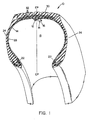
- a tire 10 which incorporates apparatus 12, which can be used to provide tire data such as the inflation pressure within the tire.
- the tire is made using at least one pair of annular beads 22 over which is wrapped at least one carcass ply 28.
- Belts 32 are disposed over carcass ply 28 in a crown area of the tire, and tread 30 is disposed over belts 32.
- Sidewalls 24 are disposed between tread 30 and beads 22.
- the tire also has an inner liner 14 which is disposed radially below carcass ply 28.
- Inflation chamber 15 contains the fluids used to inflate the tire when the tire is mounted on a rim.
- the tire illustrated is an RMT (radial medium truck) tire, but those skilled in the art will recognize that the invention may have utility in passenger tires, or any tire for which data on the pressure within the tire is needed.
- RMT radial medium truck
- a tire depending on the kind, may have up to 4 pairs of beads, up to 12 carcass plies, and up to 12 belts.
- Apparatus 12 is a transponder with a chip 12a having at least capacity to collect and transmit pressure data, and a pressure sensor 12b associated with said transponder.
- Apparatus 12 is located in the tire in a position where flexing is minimal and where a substantially flat surface can be used to assure attachment of the apparatus to the inflation chamber 15.
- the lower sidewall near the bead and the center of the crown area of the tire are examples of possible locations for attachment of apparatus 12 to the tire 10.
- apparatus 12 is disposed under the center of the tread, i.e. at the equatorial plane (EP) of the tire, and radially below carcass ply 28 and inner liner 14.
- Apparatus 12 comprises one or more integrated circuit chips 12a, an antenna 12c and any ancillary components needed for making pressure data on the tire readable.
- the transponder component of the apparatus 12 is similar to those illustrated in US-A- 5,181,975, US-A- 5,218,861, and WO99/29523, WO99/29522 and WO99/29525, which may be used to monitor tire pressure, all assigned to The Goodyear Tire and Rubber Company.
- the pressure sensor component used in the illustrated embodiment is a Case Western Reserve University device described in US-A- 5,528,452.
- the apparatus 12 may stand alone in the tire 10 to provide pressure data only.
- the pressure sensor used in the invention can be used with other sensing devices and may be associated with annular antennae to provide a 360° read around the tire as illustrated in the prior art discussed above and more specifically in WO99/29522.
- apparatus 12 When apparatus 12 is incorporated into a tire, it is placed on the surface of inflation chamber 15, said surface being inner liner 14, if the tire contains an inner liner, or the radially inner surface of carcass ply 28, if no inner liner is used, with or without an adhesive.
- apparatus 12 is surrounded by insulating rubber (not shown) to protect the electronics therein from stray electrical charges and from potentials applied by test equipment used to inspect the casings in retread operations. Insulating rubbers disclosed in the Goodyear application referred to above are suitable for this purpose.
- Rubber patch 16 is the primary means by which apparatus 12 is held in place.
- apparatus 12 be isolated from inflation chamber 15, so that dirt and foreign matter do not foul the pressure sensor, all of the surface area of patch 16 which can be placed in contact with the surface of the inflation chamber 15 is securely attached thereto, i.e. it is preferred that apparatus 12 be completely encased in rubber patch 16.
- the attachment of patch 16 to inflation chamber 15 can be made adhesively and/or by vulcanization when the tire is being built, or may be incorporated into a completed tire adhesively, for example when a tire is being submitted for retreading.
- Patch 16 is an elastomeric material, preferably natural rubber.
- apparatus 12 is not attached to or vulcanized into the tire, but is held in place by the surrounding relationship of patch 16.
- path means 18 is provided between the pressure sensor and inflation chamber 15 which permits gas molecules to migrate to and from the pressure sensor and inflation chamber 15.
- path means 18 may be provided as a pin hole in elastomeric patch 16, in reality, a pin hole has a tendency to be plugged by adhesives, the flow of rubber during vulcanization, and grime, and some means must be provided to assure that the path remains open.
- path means 18 is provided as string or cord, preferably in the form of a bleeder cord, a strip of fabric woven with bleeder cords, or a hollow filament. Such bleeder cords are described by Pepe et al in U.S. Patent 4,363,346, and by Sid-Ahmed in U.S. Patent 5,221,382 and references cited therein.
- Path means 18 may be longer than patch 16, or may be placed so that one end thereof extends beyond an edge of patch 16 or is exposed above the surface of patch 16.
- Path means 18 is placed over apparatus 12, and patch 16 is then placed over path means 18, taking care that at least one end of path means 18 remains outside the dimensions or the surface of patch 16. In the illustrated embodiment, both ends of path means 18 extend outside the dimensions of patch 16.
- path means 18 when bleeder cords or filaments are used, provides a path that makes the pressure sensor quickly responsive to pressure changes in the tire. Since bleeder cords permit flow of simple molecules, but prevent the flow of macro molecules such as grime, adhesive, and rubber, the pressure sensor is kept free of debris and grime.
- inner liner 14 When inner liner 14 is used in a tire, apparatus 12 is placed next to inner liner 14, path means 18 is placed over apparatus 12, and patch 16 is placed over path means 18 and apparatus 12 and is attached to inner liner 14.
Applications Claiming Priority (1)
| Application Number | Priority Date | Filing Date | Title |
|---|---|---|---|
| PCT/US1997/022570 WO1999029524A1 (en) | 1997-12-09 | 1997-12-09 | Pressure sensor for a tire and method therefor |
Publications (2)
| Publication Number | Publication Date |
|---|---|
| EP1037754A1 EP1037754A1 (en) | 2000-09-27 |
| EP1037754B1 true EP1037754B1 (en) | 2002-08-14 |
Family
ID=22262240
Family Applications (1)
| Application Number | Title | Priority Date | Filing Date |
|---|---|---|---|
| EP97951607A Expired - Lifetime EP1037754B1 (en) | 1997-12-09 | 1997-12-09 | Pressure sensor for a tire and method therefor |
Country Status (7)
| Country | Link |
|---|---|
| EP (1) | EP1037754B1 (ja) |
| JP (1) | JP2001525283A (ja) |
| AU (1) | AU5520698A (ja) |
| CA (1) | CA2310735A1 (ja) |
| DE (1) | DE69714794T2 (ja) |
| WO (1) | WO1999029524A1 (ja) |
| ZA (1) | ZA9810795B (ja) |
Families Citing this family (20)
| Publication number | Priority date | Publication date | Assignee | Title |
|---|---|---|---|---|
| US5971046A (en) | 1997-09-17 | 1999-10-26 | Bridgestone/Firestone, Inc. | Method and apparatus for bonding an active tag to a patch and a tire |
| US6030478A (en) | 1998-02-10 | 2000-02-29 | Bridgestone/Firestone, Inc. | Method and apparatus for removably inserting an electric tire tag into a tire |
| US6309494B1 (en) | 1998-12-04 | 2001-10-30 | Bridgestone/Firestone Research, Inc. | Method of attaching sensitive electronic equipment to the inner surface of a tire |
| US6244104B1 (en) | 1998-12-04 | 2001-06-12 | Bridgestone/Firestone Research, Inc. | Method for preparing an innerliner of a pneumatic tire for the quick bonding of an electronic monitoring device |
| US6208244B1 (en) | 1999-04-29 | 2001-03-27 | Bridgestone/Firestone Research, Inc. | Combination monitoring device and patch for a pneumatic tire and method of installing the same with a coupled antenna |
| US6474380B1 (en) | 1999-04-29 | 2002-11-05 | Bridgestone/Firestone North American Tire, Llc | Pneumatic tire and monitoring device including dipole antenna |
| US6919799B2 (en) | 1999-04-29 | 2005-07-19 | Bridgestone/Firestone North American Tire, Llc | Monitoring device and tire combination |
| JP4072802B2 (ja) * | 1999-08-27 | 2008-04-09 | 横浜ゴム株式会社 | トランスポンダを埋め込んだ空気入りタイヤ及びその製造方法 |
| US6885291B1 (en) | 1999-11-15 | 2005-04-26 | The Goodyear Tire & Rubber Company | Mouting transponders and antennas in pneumatic tires |
| CA2676102C (en) | 2000-07-26 | 2012-01-10 | Bridgestone/Firestone, Inc. | Electronic tire management system |
| BR0215784B1 (pt) | 2002-06-28 | 2013-06-04 | sistema e unidade màvel para detectar pelo menos um parÂmetro caracterÍstico de um pneumÁtico montado em um veÍculo, e, roda de veÍculo. | |
| BR0215783B1 (pt) | 2002-06-28 | 2013-11-12 | Sistema, unidade móvel para detectar pelo menos um parâmetro característico de um pneumático montado em um veículo, e, roda de veículo | |
| JP4052290B2 (ja) * | 2003-08-29 | 2008-02-27 | オムロン株式会社 | 無線icタグ接合方法、無線icタグ付き物品、及び車両 |
| US7202777B2 (en) * | 2004-01-09 | 2007-04-10 | Denso Corporation | Tire condition monitoring system |
| CN101194296B (zh) | 2005-06-10 | 2011-07-27 | 米其林研究和技术股份有限公司 | 压电器件脉冲的电感耦合 |
| FR2900098B1 (fr) * | 2006-04-25 | 2009-12-04 | Michelin Soc Tech | Support pour organe de controle d'un pneumatique, ensemble d'un support et d'un organe de controle, pneumatique et roue |
| CA2660428C (en) * | 2006-08-11 | 2012-05-29 | Bridgestone Corporation | Tire internal pressure alarm device |
| JP2009298329A (ja) * | 2008-06-13 | 2009-12-24 | Bridgestone Corp | 部品取付体及び空気入りタイヤ |
| JP7004559B2 (ja) * | 2017-12-08 | 2022-02-10 | Toyo Tire株式会社 | タイヤへの電子部品の固定構造、及び空気入りタイヤ |
| US11951782B2 (en) * | 2018-06-22 | 2024-04-09 | The Yokohama Rubber Co., Ltd. | Pneumatic tire and assembly sheet |
Family Cites Families (19)
| Publication number | Priority date | Publication date | Assignee | Title |
|---|---|---|---|---|
| US3770040A (en) | 1971-09-15 | 1973-11-06 | De Cicco M Augusta | Tire with safety indicator means |
| US4067235A (en) * | 1974-11-27 | 1978-01-10 | Consolidated Freightways, Inc. | Method and apparatus for measuring air pressure in pneumatic tires |
| JPS569637U (ja) * | 1979-07-03 | 1981-01-27 | ||
| US4363346A (en) | 1981-09-23 | 1982-12-14 | The Goodyear Tire & Rubber Company | Pneumatic tire including gas absorbing cords |
| US4578992A (en) | 1982-11-05 | 1986-04-01 | Philip E. Galasko | Detection of a low pressure condition of a vehicle tire |
| JPS60171475A (ja) | 1984-02-15 | 1985-09-04 | アイデンティフィケ−ション・デバイセス・インコ−ポレ−テッド | 識別システム |
| US4588978A (en) | 1984-06-21 | 1986-05-13 | Transensory Devices, Inc. | Remote switch-sensing system |
| US5119066A (en) * | 1988-06-06 | 1992-06-02 | Jan Ballyns | Pressure sensor system |
| DE68927374T2 (de) | 1988-08-10 | 1997-03-27 | Coin Acceptors Inc | Verkaufsautomat |
| DE3835236A1 (de) | 1988-10-15 | 1990-04-19 | Bosch Gmbh Robert | Schaltungsanordnung zur reifendruck- und temperatur-ueberwachung |
| US4911217A (en) | 1989-03-24 | 1990-03-27 | The Goodyear Tire & Rubber Company | Integrated circuit transponder in a pneumatic tire for tire identification |
| EP0417267B1 (en) | 1989-03-31 | 1995-09-20 | Hughes Aircraft Company | Vehicle tire identification system |
| US5289169A (en) | 1991-01-31 | 1994-02-22 | Frame Technology Corporation | Composite underlining functions for text processors |
| US5218861A (en) | 1991-03-27 | 1993-06-15 | The Goodyear Tire & Rubber Company | Pneumatic tire having an integrated circuit transponder and pressure transducer |
| US5181975A (en) | 1991-03-27 | 1993-01-26 | The Goodyear Tire & Rubber Company | Integrated circuit transponder with coil antenna in a pneumatic tire for use in tire identification |
| US5221382A (en) | 1991-05-10 | 1993-06-22 | The Goodyear Tire & Rubber Company | Pneumatic tire including gas absorbing cords |
| US5285189A (en) | 1991-05-14 | 1994-02-08 | Epic Technologies, Inc. | Abnormal tire condition warning system |
| US5500065A (en) | 1994-06-03 | 1996-03-19 | Bridgestone/Firestone, Inc. | Method for embedding a monitoring device within a tire during manufacture |
| US5528452A (en) | 1994-11-22 | 1996-06-18 | Case Western Reserve University | Capacitive absolute pressure sensor |
-
1997
- 1997-12-09 JP JP2000524148A patent/JP2001525283A/ja active Pending
- 1997-12-09 DE DE69714794T patent/DE69714794T2/de not_active Expired - Fee Related
- 1997-12-09 CA CA002310735A patent/CA2310735A1/en not_active Abandoned
- 1997-12-09 EP EP97951607A patent/EP1037754B1/en not_active Expired - Lifetime
- 1997-12-09 AU AU55206/98A patent/AU5520698A/en not_active Abandoned
- 1997-12-09 WO PCT/US1997/022570 patent/WO1999029524A1/en active IP Right Grant
-
1998
- 1998-11-25 ZA ZA9810795A patent/ZA9810795B/xx unknown
Also Published As
| Publication number | Publication date |
|---|---|
| JP2001525283A (ja) | 2001-12-11 |
| EP1037754A1 (en) | 2000-09-27 |
| AU5520698A (en) | 1999-06-28 |
| DE69714794T2 (de) | 2003-04-03 |
| WO1999029524A1 (en) | 1999-06-17 |
| ZA9810795B (en) | 1999-05-31 |
| DE69714794D1 (de) | 2002-09-19 |
| CA2310735A1 (en) | 1999-06-17 |
Similar Documents
| Publication | Publication Date | Title |
|---|---|---|
| EP1037754B1 (en) | Pressure sensor for a tire and method therefor | |
| EP1037755B1 (en) | Antenna for radio transponder | |
| CA2256878C (en) | Method and apparatus for monitoring conditions of a vehicle tire using a monitoring device capable of transmitting data relating to an engineering condition of the tire | |
| CA2646758C (en) | Method and apparatus for transmitting stored data and engineering conditions of a tire to a remote location | |
| US5562787A (en) | Method of monitoring conditions of vehicle tires | |
| EP1037753B1 (en) | Annular apparatus for tire data transmission, apparatus for measuring tire data having a transponder, an antenna and a pneumatic tire comprising a transponder with an antenna | |
| KR102655148B1 (ko) | 개선된 타이어 모니터링 시스템 | |
| US7021132B2 (en) | Measuring system for wheel parameters and measuring detector for such a system | |
| US4334428A (en) | Apparatus for indicating parameters sensed on a rotatable wheel | |
| EP1037752B1 (en) | Pneumatic tyre having a transponder and an annular antenna and method of manufacturing such a tyre | |
| JP4585183B2 (ja) | 環状のアンテナおよびトランスポンダ装置と、それらを空気入りタイヤ内に配置する方法 | |
| JP2532294Y2 (ja) | 集積回路応答器と圧力信号変換器付き空気タイヤ | |
| CA2482242A1 (en) | Method of integrating tire identification into a vehicle information system | |
| US20040172180A1 (en) | Wireless communications device for use in tires | |
| US20210016614A1 (en) | Tire with an integrated rfid and tpms sensor | |
| MXPA00005599A (en) | Pressure sensor for a tire and method therefor | |
| US20230161993A1 (en) | Antenna connection for integrated rfid tag and tpms sensor | |
| MXPA98010816A (en) | Method and apparatus for verifying conditions of a vehicle tire | |
| MXPA00005596A (en) | Antenna for radio transponder | |
| MXPA98010815A (en) | Method and apparatus for transmitting stored data and engineering conditions from a pneumatic to a rem site | |
| NZ330236A (en) | Tire includes monitoring transducer transmitting tire data by data band switching |
Legal Events
| Date | Code | Title | Description |
|---|---|---|---|
| PUAI | Public reference made under article 153(3) epc to a published international application that has entered the european phase |
Free format text: ORIGINAL CODE: 0009012 |
|
| 17P | Request for examination filed |
Effective date: 20000710 |
|
| AK | Designated contracting states |
Kind code of ref document: A1 Designated state(s): DE FR GB IT |
|
| GRAG | Despatch of communication of intention to grant |
Free format text: ORIGINAL CODE: EPIDOS AGRA |
|
| 17Q | First examination report despatched |
Effective date: 20011017 |
|
| GRAG | Despatch of communication of intention to grant |
Free format text: ORIGINAL CODE: EPIDOS AGRA |
|
| GRAH | Despatch of communication of intention to grant a patent |
Free format text: ORIGINAL CODE: EPIDOS IGRA |
|
| GRAH | Despatch of communication of intention to grant a patent |
Free format text: ORIGINAL CODE: EPIDOS IGRA |
|
| GRAA | (expected) grant |
Free format text: ORIGINAL CODE: 0009210 |
|
| AK | Designated contracting states |
Kind code of ref document: B1 Designated state(s): DE FR GB IT |
|
| REG | Reference to a national code |
Ref country code: GB Ref legal event code: FG4D |
|
| REF | Corresponds to: |
Ref document number: 69714794 Country of ref document: DE Date of ref document: 20020919 |
|
| ET | Fr: translation filed | ||
| PLBE | No opposition filed within time limit |
Free format text: ORIGINAL CODE: 0009261 |
|
| STAA | Information on the status of an ep patent application or granted ep patent |
Free format text: STATUS: NO OPPOSITION FILED WITHIN TIME LIMIT |
|
| 26N | No opposition filed |
Effective date: 20030515 |
|
| PGFP | Annual fee paid to national office [announced via postgrant information from national office to epo] |
Ref country code: GB Payment date: 20061106 Year of fee payment: 10 |
|
| PGFP | Annual fee paid to national office [announced via postgrant information from national office to epo] |
Ref country code: FR Payment date: 20061201 Year of fee payment: 10 |
|
| PGFP | Annual fee paid to national office [announced via postgrant information from national office to epo] |
Ref country code: DE Payment date: 20061229 Year of fee payment: 10 |
|
| PGFP | Annual fee paid to national office [announced via postgrant information from national office to epo] |
Ref country code: IT Payment date: 20071215 Year of fee payment: 11 |
|
| GBPC | Gb: european patent ceased through non-payment of renewal fee |
Effective date: 20071209 |
|
| PG25 | Lapsed in a contracting state [announced via postgrant information from national office to epo] |
Ref country code: DE Free format text: LAPSE BECAUSE OF NON-PAYMENT OF DUE FEES Effective date: 20080701 |
|
| REG | Reference to a national code |
Ref country code: FR Ref legal event code: ST Effective date: 20081020 |
|
| PG25 | Lapsed in a contracting state [announced via postgrant information from national office to epo] |
Ref country code: GB Free format text: LAPSE BECAUSE OF NON-PAYMENT OF DUE FEES Effective date: 20071209 |
|
| PG25 | Lapsed in a contracting state [announced via postgrant information from national office to epo] |
Ref country code: FR Free format text: LAPSE BECAUSE OF NON-PAYMENT OF DUE FEES Effective date: 20071231 |
|
| PG25 | Lapsed in a contracting state [announced via postgrant information from national office to epo] |
Ref country code: IT Free format text: LAPSE BECAUSE OF NON-PAYMENT OF DUE FEES Effective date: 20081209 |