EP1037699B1 - Filter element and method and adhesive application device for the production thereof - Google Patents
Filter element and method and adhesive application device for the production thereof Download PDFInfo
- Publication number
- EP1037699B1 EP1037699B1 EP98966205A EP98966205A EP1037699B1 EP 1037699 B1 EP1037699 B1 EP 1037699B1 EP 98966205 A EP98966205 A EP 98966205A EP 98966205 A EP98966205 A EP 98966205A EP 1037699 B1 EP1037699 B1 EP 1037699B1
- Authority
- EP
- European Patent Office
- Prior art keywords
- adhesive
- pleat
- filter material
- spacers
- application device
- Prior art date
- Legal status (The legal status is an assumption and is not a legal conclusion. Google has not performed a legal analysis and makes no representation as to the accuracy of the status listed.)
- Expired - Lifetime
Links
- 239000000853 adhesive Substances 0.000 title claims description 138
- 230000001070 adhesive effect Effects 0.000 title claims description 134
- 238000000034 method Methods 0.000 title claims description 15
- 238000004519 manufacturing process Methods 0.000 title claims description 12
- 239000000463 material Substances 0.000 claims abstract description 79
- 125000006850 spacer group Chemical group 0.000 claims abstract description 53
- 239000012530 fluid Substances 0.000 claims description 11
- 238000012545 processing Methods 0.000 claims description 5
- 230000003247 decreasing effect Effects 0.000 claims description 2
- 230000009347 mechanical transmission Effects 0.000 claims description 2
- 230000008569 process Effects 0.000 claims description 2
- 230000008602 contraction Effects 0.000 claims 1
- 230000003014 reinforcing effect Effects 0.000 claims 1
- 230000001360 synchronised effect Effects 0.000 claims 1
- 239000007788 liquid Substances 0.000 abstract description 2
- 238000005192 partition Methods 0.000 abstract 5
- 238000004049 embossing Methods 0.000 description 22
- 239000011324 bead Substances 0.000 description 13
- 239000003292 glue Substances 0.000 description 10
- 230000015572 biosynthetic process Effects 0.000 description 5
- 238000012986 modification Methods 0.000 description 5
- 230000004048 modification Effects 0.000 description 5
- 239000004831 Hot glue Substances 0.000 description 4
- 230000037303 wrinkles Effects 0.000 description 4
- 239000010410 layer Substances 0.000 description 3
- 239000001913 cellulose Substances 0.000 description 2
- 230000006835 compression Effects 0.000 description 2
- 238000007906 compression Methods 0.000 description 2
- 238000001816 cooling Methods 0.000 description 2
- 238000005520 cutting process Methods 0.000 description 2
- 238000013461 design Methods 0.000 description 2
- 238000010586 diagram Methods 0.000 description 2
- 230000000694 effects Effects 0.000 description 2
- 238000005516 engineering process Methods 0.000 description 2
- 239000007789 gas Substances 0.000 description 2
- 239000011521 glass Substances 0.000 description 2
- VNWKTOKETHGBQD-UHFFFAOYSA-N methane Chemical compound C VNWKTOKETHGBQD-UHFFFAOYSA-N 0.000 description 2
- 239000004745 nonwoven fabric Substances 0.000 description 2
- 239000002245 particle Substances 0.000 description 2
- 235000011837 pasties Nutrition 0.000 description 2
- 230000009467 reduction Effects 0.000 description 2
- 230000000087 stabilizing effect Effects 0.000 description 2
- 229920003043 Cellulose fiber Polymers 0.000 description 1
- 239000004819 Drying adhesive Substances 0.000 description 1
- JOYRKODLDBILNP-UHFFFAOYSA-N Ethyl urethane Chemical compound CCOC(N)=O JOYRKODLDBILNP-UHFFFAOYSA-N 0.000 description 1
- 238000004026 adhesive bonding Methods 0.000 description 1
- 239000012790 adhesive layer Substances 0.000 description 1
- 238000004378 air conditioning Methods 0.000 description 1
- 238000007605 air drying Methods 0.000 description 1
- 230000006399 behavior Effects 0.000 description 1
- 210000000988 bone and bone Anatomy 0.000 description 1
- 238000004364 calculation method Methods 0.000 description 1
- 229920002678 cellulose Polymers 0.000 description 1
- 239000000919 ceramic Substances 0.000 description 1
- 239000000356 contaminant Substances 0.000 description 1
- 230000008021 deposition Effects 0.000 description 1
- 230000000881 depressing effect Effects 0.000 description 1
- 238000001514 detection method Methods 0.000 description 1
- 238000011161 development Methods 0.000 description 1
- 230000018109 developmental process Effects 0.000 description 1
- 238000002474 experimental method Methods 0.000 description 1
- 239000004744 fabric Substances 0.000 description 1
- 239000000835 fiber Substances 0.000 description 1
- 238000001914 filtration Methods 0.000 description 1
- 239000006260 foam Substances 0.000 description 1
- 239000006261 foam material Substances 0.000 description 1
- 238000005187 foaming Methods 0.000 description 1
- 239000012943 hotmelt Substances 0.000 description 1
- 238000005470 impregnation Methods 0.000 description 1
- 229910052500 inorganic mineral Inorganic materials 0.000 description 1
- 239000011707 mineral Substances 0.000 description 1
- 239000000203 mixture Substances 0.000 description 1
- 239000003345 natural gas Substances 0.000 description 1
- 230000035515 penetration Effects 0.000 description 1
- 239000004033 plastic Substances 0.000 description 1
- 230000036316 preload Effects 0.000 description 1
- 238000007639 printing Methods 0.000 description 1
- 239000011541 reaction mixture Substances 0.000 description 1
- 238000004064 recycling Methods 0.000 description 1
- 230000003252 repetitive effect Effects 0.000 description 1
- 230000004044 response Effects 0.000 description 1
- 238000007493 shaping process Methods 0.000 description 1
- 238000004088 simulation Methods 0.000 description 1
- 238000003892 spreading Methods 0.000 description 1
- 230000007480 spreading Effects 0.000 description 1
- 230000006641 stabilisation Effects 0.000 description 1
- 238000011105 stabilization Methods 0.000 description 1
- 238000003860 storage Methods 0.000 description 1
- 239000000126 substance Substances 0.000 description 1
- 239000012209 synthetic fiber Substances 0.000 description 1
- 229920002994 synthetic fiber Polymers 0.000 description 1
- 229920001169 thermoplastic Polymers 0.000 description 1
- 239000004416 thermosoftening plastic Substances 0.000 description 1
- 238000011144 upstream manufacturing Methods 0.000 description 1
- 238000009423 ventilation Methods 0.000 description 1
Images


Classifications
-
- B—PERFORMING OPERATIONS; TRANSPORTING
- B01—PHYSICAL OR CHEMICAL PROCESSES OR APPARATUS IN GENERAL
- B01D—SEPARATION
- B01D46/00—Filters or filtering processes specially modified for separating dispersed particles from gases or vapours
- B01D46/52—Particle separators, e.g. dust precipitators, using filters embodying folded corrugated or wound sheet material
- B01D46/521—Particle separators, e.g. dust precipitators, using filters embodying folded corrugated or wound sheet material using folded, pleated material
- B01D46/523—Particle separators, e.g. dust precipitators, using filters embodying folded corrugated or wound sheet material using folded, pleated material with means for maintaining spacing between the pleats or folds
-
- B—PERFORMING OPERATIONS; TRANSPORTING
- B01—PHYSICAL OR CHEMICAL PROCESSES OR APPARATUS IN GENERAL
- B01D—SEPARATION
- B01D29/00—Filters with filtering elements stationary during filtration, e.g. pressure or suction filters, not covered by groups B01D24/00 - B01D27/00; Filtering elements therefor
- B01D29/01—Filters with filtering elements stationary during filtration, e.g. pressure or suction filters, not covered by groups B01D24/00 - B01D27/00; Filtering elements therefor with flat filtering elements
- B01D29/012—Making filtering elements
-
- B—PERFORMING OPERATIONS; TRANSPORTING
- B01—PHYSICAL OR CHEMICAL PROCESSES OR APPARATUS IN GENERAL
- B01D—SEPARATION
- B01D29/00—Filters with filtering elements stationary during filtration, e.g. pressure or suction filters, not covered by groups B01D24/00 - B01D27/00; Filtering elements therefor
- B01D29/01—Filters with filtering elements stationary during filtration, e.g. pressure or suction filters, not covered by groups B01D24/00 - B01D27/00; Filtering elements therefor with flat filtering elements
- B01D29/016—Filters with filtering elements stationary during filtration, e.g. pressure or suction filters, not covered by groups B01D24/00 - B01D27/00; Filtering elements therefor with flat filtering elements with corrugated, folded or wound filtering elements
-
- B—PERFORMING OPERATIONS; TRANSPORTING
- B01—PHYSICAL OR CHEMICAL PROCESSES OR APPARATUS IN GENERAL
- B01D—SEPARATION
- B01D46/00—Filters or filtering processes specially modified for separating dispersed particles from gases or vapours
- B01D46/0001—Making filtering elements
-
- B—PERFORMING OPERATIONS; TRANSPORTING
- B01—PHYSICAL OR CHEMICAL PROCESSES OR APPARATUS IN GENERAL
- B01D—SEPARATION
- B01D46/00—Filters or filtering processes specially modified for separating dispersed particles from gases or vapours
- B01D46/10—Particle separators, e.g. dust precipitators, using filter plates, sheets or pads having plane surfaces
-
- B—PERFORMING OPERATIONS; TRANSPORTING
- B01—PHYSICAL OR CHEMICAL PROCESSES OR APPARATUS IN GENERAL
- B01D—SEPARATION
- B01D46/00—Filters or filtering processes specially modified for separating dispersed particles from gases or vapours
- B01D46/24—Particle separators, e.g. dust precipitators, using rigid hollow filter bodies
- B01D46/2403—Particle separators, e.g. dust precipitators, using rigid hollow filter bodies characterised by the physical shape or structure of the filtering element
- B01D46/2411—Filter cartridges
-
- B—PERFORMING OPERATIONS; TRANSPORTING
- B05—SPRAYING OR ATOMISING IN GENERAL; APPLYING FLUENT MATERIALS TO SURFACES, IN GENERAL
- B05C—APPARATUS FOR APPLYING FLUENT MATERIALS TO SURFACES, IN GENERAL
- B05C5/00—Apparatus in which liquid or other fluent material is projected, poured or allowed to flow on to the surface of the work
- B05C5/02—Apparatus in which liquid or other fluent material is projected, poured or allowed to flow on to the surface of the work the liquid or other fluent material being discharged through an outlet orifice by pressure, e.g. from an outlet device in contact or almost in contact, with the work
- B05C5/0225—Apparatus in which liquid or other fluent material is projected, poured or allowed to flow on to the surface of the work the liquid or other fluent material being discharged through an outlet orifice by pressure, e.g. from an outlet device in contact or almost in contact, with the work characterised by flow controlling means, e.g. valves, located proximate the outlet
-
- B—PERFORMING OPERATIONS; TRANSPORTING
- B01—PHYSICAL OR CHEMICAL PROCESSES OR APPARATUS IN GENERAL
- B01D—SEPARATION
- B01D2265/00—Casings, housings or mounting for filters specially adapted for separating dispersed particles from gases or vapours
- B01D2265/04—Permanent measures for connecting different parts of the filter, e.g. welding, glueing or moulding
Definitions
- the invention relates to a filter element according to the preamble of claim 1 and a method of manufacture such as well as an adhesive application device and an arrangement for producing a fluid filter insert with such an adhesive application device.
- Fluid filter elements serve to remove contaminants from a flowing fluid (especially air or technical Gases, but possibly also liquids). Filter elements are currently predominantly used in air filters used which is a nonwoven fabric, in particular made of glass, cellulose or synthetic fibers.
- the filter medium is conventional Filtering the type in question (so-called Minipleats) meandering to essentially parallel Folded walls folded so that a number of over Fold edges adjoining each other, somewhat in the surface curved folds. These are in the inflow area in a small one and not because of the curvature exactly defined angle to the walls of the folding and thereby transversely to the direction of the fold edges of the one to be cleaned Flow against medium.
- Minipleats meandering to essentially parallel Folded walls folded so that a number of over Fold edges adjoining each other, somewhat in the surface curved folds.
- DE 43 45 122 A1 describes a filter insert and a method known for its manufacture, in which on an embossed Filter material of the type mentioned above is not just a thin layer of adhesive to glue the embossed surveys is applied, but an increasing Glue shop that itself at least in sections has a certain height and thus as an additional spacer (in addition to the embossed surveys). With this procedure can be used to filter particles with advantageous properties and create very large fold heights However, the procedure is because of the demanding combination of filter material stamping and controlled adhesive application consuming.
- the invention is based, a simple and Filter element of the generic type which can be produced inexpensively Kind with good fluidic properties and high mechanical stability and a method for To specify the manufacture of this filter element. Farther is to provide an improved adhesive application device be, in particular the production of novel Fluid filter inserts enabled.
- the task is carried out according to its various aspects a filter element with the features of claim 1 or a method with the features of claim 7 and further through an adhesive application device with the Features of claim 11 and an arrangement according to claim 25 solved.
- the invention includes the idea of waiving on depressions embossed in the filter material zigzag, stiffened filter material configuration alone with spacers attached to the filter material with along the web in a predetermined manner variable height to realize.
- the spacers become in particular in the same direction with the narrowing of the cross-section the fold in question towards the sole of the fold or the fold base continuously flatter, or there are between two fold walls two or more separate spacers provided, and a spacer adjacent to the fold base is in each case thinner or flatter than one of these more distant.
- the spacers can be in an advantageous embodiment of the inventive idea with which one particularly high rigidity of the structure is achieved over the larger Part of the length of the fold walls should be formed.
- this is exclusive in the areas where the fold walls have a large distance, an applied adhesive spacer provided while in the fields of Wrinkle bases or soles no spacer available or the adhesive has no appreciable thickness by the amount applied is such that it is in the essentially penetrates into the filter material. If in no adhesive was applied to these areas at all is, the filterable increases in an advantageous manner Area of the filter element.
- the spacers can be dimensioned in this way in their height profile be that a spacer for the desired Total distance between the fold walls ensures by touches an area of the fold wall facing him, in where no other spacer is placed. Execution and arrangement of the individual spacers can also be chosen so that when folding - at least in the fold peak areas - two mutually facing spacers touch and their heights (in connected Condition) add to the local fold spacing to be set.
- Folded walls preferably with both sides or Provide spacers facing surfaces, see above that the fold walls are firmly against adjacent on both sides Support fold walls.
- this is not absolutely necessary; in principle, each can also be glued second pair of adjacent fold walls may be sufficient.
- the spacers are created by applying an adhesive, so the perpendicular to the fold edges, i.e. when applying in the direction of the filter material web or decreasing height advantageous by controlling the pro Time unit or per unit length of the filter material web amount of adhesive emerging from an application nozzle become.
- the amount of adhesive per unit of time can control the cross section accordingly the outlet opening of the applicator become, i.e. specifically when approaching the future Folded lines marking fold lines whose cross section be reduced and enlarged when removed from them.
- variation is possible a corresponding amount of adhesive per unit of time Control of the outlet pressure from the application device be made.
- the applied per unit length of the filter material web Amount of adhesive by varying the relative speed between the material web and the outlet opening Application device can be changed, e.g. additionally during the passage of the filter material web is moved.
- the order quantity can also be controlled by temperature to be influenced.
- Viscosity and thixotropy of the adhesive when applied must be coordinated with the surface properties of the filter material so that a Spreading of the adhesive prevented with a larger order quantity becomes.
- the spacer the glue
- Alternatively or in combination with a quantity-controlled Application can be the adhesive application in the direction the longitudinal extent of the filter material web at least interrupted once and the plotted per unit length Amount of adhesive beyond the break in Direction towards the embossing marking the sole of a fold be chosen lower than on this side of the interruption, i.e. in the wide open part of the fold where the spacer must be higher.
- each application unit has its own metering device has and the dosing devices a common Control device is assigned.
- the dosing device preferably to implement a dosing cycle time of less than 1 s, especially less than 0.2 s.
- the period is the dosing cycle time Repetitive job profile sections understood.
- Dosing cones are formed and in which mechanical, pneumatic, hydraulic, electromagnetic or electromotive actuators with high Response speed for shifting the dosing cone are provided.
- actuators in a essential execution based on mechanical components a cam device and one of the cam devices counteracting bias spring device provided.
- Another preferred embodiment comprises a motor-gear unit, the one in particular with a preprogrammed one Job profile of finely controllable stepper motor may include.
- the order units together a fast-acting pressure control device for Assign control of the adhesive supply pressure.
- the control device is at least one Transducer for a location feature and, if necessary, the Throughput speed of the surface material or a a processing feature creating the same position feature assigned.
- a transducer is in particular by a transport or embossing shaft of a transport and / or Embossing device formed for the sheet material or one those assigned to the angle of rotation detection.
- Control expediently includes the control device a the cam device with the transport or Embossing shaft connecting and synchronizing mechanical Transmission equipment.
- an electronic control has a programmable one Processing unit on the input side with the transducer (or in practice also several transducers) and on the output side with the dosing device and / or the pressure control device is connected.
- a preferred system especially for the production of fluid filter inserts additionally comprises at least one embossing device for the formation of fold edge embossing and if necessary, additional stiffening depressions in an as Filter material trained surface material and means to synchronize the embossing device with the control the adhesive application device so that the local Cross-section of the adhesive traces in a predetermined spatial Assignment to the fold edge embossing and / or Wells stands.
- groups are quasi-less Glue threads without a break on a quasi-endless Filter material web can be applied, it can also be abr separated adhesive aggregates with predetermined in the sequence Height profile are formed.
- the processing unit should be in the interest of a flexible Use of the system for different filter configurations with a short changeover time a profile memory for storing predetermined adhesive trace profiles in assignment on the position of the fold edge embossing and / or the depressions.
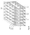
- Fig. 1a shows a schematic, not to scale one cuboid in shape
- Filter insert 1 made of a filter fleece 2 the embossing lines or fold edges 2a is folded in a zigzag shape, so that each point between two fold edges 2a Wrinkle walls 2b enclosing angles result.
- Adhesive beads 3 applied.
- the adhesive beads 3 on the two surfaces of the filter fleece 2 laterally offset from one another, in practice, however, an arrangement is preferred the adhesive beads in a lateral alignment with each other ( “Above each other").
- the adhesive aggregates 3 opposite fold walls 2b are (what in the drawing not shown) fused together, whereby in cured state of the adhesive the appropriate Folded walls firmly connected and essentially are rigidly supported against each other and thereby the filter element 1 is mechanically stiff.
- Fig. 1b shows a compared to the embodiment of Fig. 1a modified filter insert 11 with a smaller pleat angle, i.e. with the same fold height, smaller maximum fold spacing.
- the fold walls 12b are each short here Adhesive aggregates 13a, 13b in the opening area of the fold walls (below the fold peaks 12a) and 13c near the Folded sole connected together.
- 1c shows a detail as a further modification from a filter element 21 with a further reduced pleat angle and distance.
- the distance is also in the opening or fold peak area so small that it as well as in the area of the folds by means of the adhesive points 23a, bridged with individual adhesive points 23b that can be directly on the opposite fold wall 22b cling.
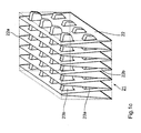
- FIG. 2a shows a cross-sectional illustration of the fold arrangement a further filter element 31 in a sectional plane parallel to the longitudinal extent of the filter fleece 32.
- the formation of the adhesive spacer 33 corresponds basically Fig. 1a, but these are different from Version shown there only in every second through fold walls 32b fold formed between fold edges 32a intended.
- the filter material only needs one What surface to be provided with adhesive beads technology simplified and a cost reduction in Manufacturing allowed.
- FIG. 2b shows an alternative embodiment of a filter element 41, in an arrangement similar to FIG. 2a of the filter material 42 - namely with only one-sided fixation that extending between fold edges 42a Folded walls 42b - only the smaller part of the length or height the fold walls with adhesive aggregates 43a and 43b and 43c is provided.
- adhesive aggregates 43a and 43b form a real spacer by adding their heights, while that arranged directly in the pleated sole 42a
- Adhesive point 43c only additionally stabilizing and has a vibration-dampening effect.
- the adhesive aggregate is also on both surfaces of the fold walls possible, then one of Fig. 1b Similar version with fixation of the fold walls on both sides arises.
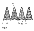
- Fig. 2c shows a similar to the arrangement of Fig. 2a Filter element 51 made of a filter fleece 52, in which the Folded edges 52a of one (in the figure of the lower) fold edge region by flat extensions 53a of the adhesive aggregates 53 are bridged as to the position of the Fold walls 52b additionally stabilized.
- FIG. 3 is a schematic cross-sectional illustration of a in the outer shape of hollow cylindrical filter insert 61 according to a further embodiment of the invention.
- the hollow cylindrical outer shape causes the alternating Sequence of further folds 61a and narrow folds 61b of the filter fleece 62.
- the arrangement of the in the wide folds 61a placed spacer 63a is similar to that in the cuboid filter insert according to FIG. 2b.
- the difference to this is here in the pleated soles 62a.1 the wide one Wrinkles 61a no glue applied and the fold walls 62b are glued on both sides, being in the tight folds 61b only a thin adhesive layer 63b is provided that extends into the fold sole 62a.2 there.
- the spacers can, as in the above versions, by applying an adhesive with a controlled thickness (Height) with subsequent curing of the (preferably one-component) Be generated adhesive.
- the spacers with that shown in the figures Cross-sectional shape by foaming a corresponding Reaction mixture - for example a quickly processable Two-component mixture based on urethane - too form.
- Prefabricated spacers - for example made of organic or plastic recycling material - on the filter material web to stick on or also during or immediately after folding into the fold package.
- FIG. 4a to 4c show the essential diagrams Steps of forming a zigzag folded minipleat filter element of the structure shown in Fig. 2a and the associated device components in three variants.
- a quasi-endless web of filter material 100 is created via a roller section 101, first of all to an embossing device 102 for embossing the fold lines 103 for the later Convolution fed.
- the embossing device 102 also has a die 102a, an embossing roller 102b with an embossing roller rotation angle sensor 102c.
- the embossed filter material web 100 After there the fold lines 103 - while registering their Relative position on the way of capturing the embossing bar over the angle of rotation sensor 102c - have been impressed, the embossed filter material web 100 'passes through an adhesive application device 104.
- This has a plurality of adjacent application units 104a controllable adhesive discharge per unit of time (of which in only one is shown in the figure) and a control unit 104b and an interface 104c to the embossing device 102 on.
- a hot glue is applied by means of the application units 104a ("hot melt") or foam adhesive or an ordinary one air-drying adhesive under precise control the control unit 104b to predetermined sections of the material web 100 with predetermined cross-sectional and in particular Height profile for the formation of different adhesive beads 105.1 to 105.3 plotted.
- application units 104a hot melt
- foam adhesive or an ordinary one air-drying adhesive under precise control the control unit 104b to predetermined sections of the material web 100 with predetermined cross-sectional and in particular Height profile for the formation of different adhesive beads 105.1 to 105.3 plotted.
- side by side arranged order units will be one Plurality of at the same height and with the same height profile adjacent adhesive beads formed what cannot be seen in the side view.
- the control unit 104b is used to specify the correct position and the predetermined height profile of the adhesive beads relative to the position of the fold lines 103 above the interface 104c the signal of the embossing roller rotation angle sensor 102c fed.
- Control signals for setting the outlet cross-section of the application units The control unit directs 104a for the order quantity control from the predetermined (possibly by not shown here conventional sensors monitored online) throughput speed the filter material web 100 'or rotational speed of the embossing rollers and in a characteristic curve memory 104d programmed data on the adhesive and Filter material properties and the desired filter geometry from.
- every second fold line 103 adhesive points 105.1 and on the neighboring ones Folded wall sections adhesive beads 105.2 and 105.3 plotted with a predetermined height increase.
- the corresponding stored control characteristic for a dosing cycle that for a fold unit of the filter material predetermined and for all fold units in the same way repeated use therefore includes for this execution of the glue traces sections where the glue dispensing is zero per unit of time (Closing times of all order units 104a), sections, in which this has a fixed value ("constant opening times") and sections in which it rises steadily or drops (“variable opening times"). But there are also Execution of the adhesive traces without any interruption possible, where of course no closing times are provided are.
- the characteristic curve is not complete corresponds to the height profile of the adhesive traces to be generated, but the dynamic behavior of the adhesive invoice after leaving the order opening represents, in particular through its physicochemical parameters and to some extent through the filter material surface is determined. So with one stands for certain Preferred embodiments of the invention - gel-like Consistency and relatively high surface tension the filter material the first derivative of the amount of adhesive according to the time in an almost linear relationship to the given one Height increase of the adhesive traces, while with soft pasty Consistency and / or lower surface tension there is a rather quadratic dependency.
- the setting the characteristic curve for the specific application is usually based on a series of experiments or simulation calculations the specialist has no need to go out further possible.
- a filter geometry of the type shown in Fig. 1 would be the opening sections of the characteristic curve mentioned above in at least two areas with different, but within the ranges of constant first derivative of the Glue amount divided by time.
- the embossed and with the adhesive aggregates 105.1 to 105.3 provided filter material web 100 "to a folding station 106, where they are on a transport device 106a the fold lines 103 is folded such that the adhesive beads 105.2 and 105.3 load-bearing fold walls 100.1 " and 100.2 "face each other and the adhesive beads be brought into contact with each other. In this condition the adhesive is cured.
- This is in the figure - in case of using a hot glue - by one Cooling fan 106b symbolizes, but can - depending on the type of used adhesive - also through a two-component reaction or by air humidity or by simple Cool the hot glue.
- Fig. 4b is a modification of the method and System shown in Fig. 4a. Those corresponding to Fig. 4a Components and process steps are not described again.
- the design of the folding station 106 'differs which here has two transport devices 106a.1' and 106a.2 'running at different speeds v 1 , v 2 .
- Folding at a lower speed v 1 initially causes the filter material 100 "to be tightly folded, in which the adhesive aggregates 105.2 and 105.3 are fused together with a certain amount of pressure and the adhesive point 105.1 is pressed into the fold sole at the fold line 103 a primary fold package 107 with a small fold distance, which has not yet been fixed due to the fact that the adhesive has not yet cured.
- FIG. 4c shows a system modified compared to FIG. 4a with a purely mechanical controller 104 'that essentially one engaged with the embossing shaft 102b Timing belt drive 104c 'and one driven by this Camshaft 104b ', which on the application units 104a acts mechanically.
- a separate transducer for the angular position of the embossing shaft can be found here omitted because the position synchronization of the adhesive tracks with the fold edges through the initial adjustment of the toothed belt drive and the cam control shaft he follows.
- the other system components correspond the system shown in Fig. 4a and are not here described again.
- a compression spring 46 which is supported against a plate 44b on the metering rod 44 and thus upwards - i.e. into the application nozzle 42 fully releasing position - preloaded.
- a cam device presses against the upper end of the metering rod 47, the metering rod against the biasing force the compression spring 46 presses down and in cooperation the position of the dosing cone with the pressure spring 44a relative to the application nozzle 41a and thus the effective one Cross section of the latter controls. This will ultimately the amount of adhesive dispensed per unit of time and in particular the local height of the adhesive track 105 on the Filter material 100 controlled.
- the application unit 40 ' differs from the one described above by a pneumatic drive by means of pressure-controlled compressed air supply via a Compressed air supply line 47 'in a pressure chamber 45'.
- This will - in addition to the wall of the application unit - by a Plate 44b from Fig. 4a similar, but against the inner wall sealed pressure plate 44b ', which here upper end of the (so far modified) metering rod 44 ' forms.
- the position of the dosing cone 44a 'relative to Application nozzle 41a and the effective cross section of the latter - and thus the amount of adhesive discharged per unit of time - are determined by the ratio of the spring preload determined for the momentary pressure in the pressure chamber 45 '.
- Pressure fluid can be used, especially a hydraulic one Drive.
- the execution of an application unit is basically similar 40 "according to FIG. 5c, in which the Place the compressed air control according to Fig. 4b an electromagnetic Position control of the metering rod 44 "via a Magnetic coil 47 “occurs, which is a permanent magnetic engages upper section 44b "of the metering rod 44".
- the application unit 40 '"according to FIG. 5d is - similar to 5a - mechanically controlled, and by a stepper motor 47 “', the metering rod 44 "'over a fine thread 44b'" at the upper end accordingly drives a pre-stored step sequence program.
- a stepper motor 47 "' the metering rod 44 "'over a fine thread 44b'" at the upper end accordingly drives a pre-stored step sequence program.
- an optional intermediate gear not shown
- a back pressure spring arrangement is not necessary in this version.
- the adhesive is fed to the application units preferably in a constant pressure system with a Limit pressure controlled feed pump, its delivery capacity is significantly larger than the maximum current order quantity all order units together.
- the application units according to FIGS. 5a to 5c enable appropriate shaping of the dosing cone and the nozzle inner wall a temporary increase in order printing at the outlet opening opposite the supply pressure or the average adhesive chamber internal pressure through the dosing element, i.e. a forced ejection of adhesive, in the sections of the dosing cycle in which a high altitude the trace of adhesive is required. This can be due to the possible reduction of the supply pressure energy savings and possibly a higher accuracy of the adhesive application can be achieved in the middle height range.
- FIG. 6a and 6b is in two different positions
- a schematic version of a modified version an application unit 50 shown, which is advantageous Include the formation of adhesive traces 105a and 105b approximately constant width, but variable height on the Filter material 100 allows.
- the application unit 50 has a nozzle 51 with a rectangular cross section and instead of Dosing cone a correspondingly prismatic shaped dosing element 52 on that the cross section of the nozzle 51 of one edge of the rectangle is narrowed asymmetrically.
- the metering element 52 is also at a constant distance from continuous filter material 100 - in particular this sliding touching and if necessary defined depressing - kept while changing the order cross section by moving the nozzle shell relative to the dosing element and to the filter material surface.
Abstract
Description
Die Erfindung betrifft ein Filterelement nach dem Oberbegriff des Anspruchs 1 und ein Verfahren zur Herstellung eines solchen sowie eine Klebstoff-Auftragvorrichtung und eine Anordnung zur Herstellung eines Fluidfiltereinsatzes mit einer solchen Klebstoff-Auftragvorrichtung.The invention relates to a filter element according to the preamble of claim 1 and a method of manufacture such as well as an adhesive application device and an arrangement for producing a fluid filter insert with such an adhesive application device.
Fluidfilterelemente dienen dazu, Verunreinigungen aus einem hindurchströmenden Fluid (insbesondere Luft oder technischen Gasen, ggfs. aber auch Flüssigkeiten) abzuscheiden. In Luftfiltern werden gegenwärtig überwiegend Filterelemente verwendet, welche ein Faservlies, insbesondere aus Glas-, Cellulose- oder synthetischen Fasern, aufweisen.Fluid filter elements serve to remove contaminants from a flowing fluid (especially air or technical Gases, but possibly also liquids). Filter elements are currently predominantly used in air filters used which is a nonwoven fabric, in particular made of glass, cellulose or synthetic fibers.
Um die effektive Filterfläche gegenüber der Anströmfläche des Filters zu vergrößern, ist das Filtermedium bei herkömmlichen Filtern der in Rede stehenden Art (sogenannten Minipleats) mäanderförmig zu im wesentlichen parallelen Faltenwänden zusammengelegt, so daß eine Anzahl von über Faltenkanten aneinander anschließenden, in der Fläche etwas gekrümmten Falten entsteht. Diese werden im Einströmbereich in einem kleinen und aufgrund der Krümmung nicht exakt definierten Winkel zu den Wandungen der Faltung und dabei quer zur Richtung der Faltenkanten von dem zu reinigenden Medium angeströmt.The effective filter area compared to the inflow area of the filter, the filter medium is conventional Filtering the type in question (so-called Minipleats) meandering to essentially parallel Folded walls folded so that a number of over Fold edges adjoining each other, somewhat in the surface curved folds. These are in the inflow area in a small one and not because of the curvature exactly defined angle to the walls of the folding and thereby transversely to the direction of the fold edges of the one to be cleaned Flow against medium.
Durch die Ungleichmäßigkeit der Faltenstruktur, Materialablagerung - insbesondere auch die Ablagerung größerer Partikel - an der Anströmseite des Filters und Wirbelbildungen im anströmenden Fluid usw. kommt es beim Durchströmen des Filters zu Inhomogenitäten der Fluidströmung, die die Faltenanordnung einer erheblichenen mechanischen Wechselbelastung aussetzen und letztlich Deformationen bewirken können. Zudem ist eine im wesentlichen parallele Faltung des Filtermaterials strömungstechnisch nicht optimal.Due to the irregularity of the fold structure, material deposition - In particular, the larger deposit Particles - on the upstream side of the filter and vortex formation in the inflowing fluid etc. it occurs when flowing through of the filter to inhomogeneities in the fluid flow, the the fold arrangement of a considerable mechanical alternating load suspend and ultimately cause deformations can. There is also an essentially parallel fold the flow of the filter material is not optimal.
Bei Filtern mit größerer Faltenhöhe ist es seit längerem üblich, in das Filtermaterial Vertiefungen mit alternierender Orientierung und derart vorgegebener Gestalt einzuprägen, daß sich beim Falten des Materials die Vertiefungen benachbarter Faltenwände aneinanderlegen und gegeneinander abstützen, so daß eine Stabilisierung der Konfiguration erreicht wird. Die Gestalt der Einprägungen kann so vorbestimmt sein, daß sich eine präzise Zickzack-Faltung mit ebenen Faltenwänden ergibt; vgl. US 3 531 920. Auf die Einprägungen kann zusätzlich ein Kleber aufgetragen werden, der beim Falten ein bereichsweise festes Aneinanderhaften der Faltenwände und damit eine weitere Versteifung bewirkt; vgl. etwa DE 41 26 126 A1.It has been with filters with a larger pleat height for a long time usual, in the filter material wells with alternating To memorize orientation and such a given shape, that when you fold the material, the depressions Put adjacent fold walls together and against each other support so that a stabilization of the configuration is achieved. The shape of the imprints can be so be predetermined to have a precise zigzag fold with flat fold walls results; see. US 3,531,920 An adhesive can also be applied which adheres firmly to one another when folded the fold walls and thus a further stiffening causes; see. about DE 41 26 126 A1.
Aus DE 40 38 966 A1 ist es auch bekannt, halbkugelförmige Abstandshalter auf die Faltenwände aufzusetzen bzw. in diese einzufügen. Die Abstandshalter können - wie in der vorgenannten Druckschrift als eine Möglichkeit erwähnt oder auch in DE 30 37 019 A1 ausgeführt - Klebstoffaggregate, insbesondere in Fadenform, sein. Diese haben neben der abstandshaltenden zusätzlich eine die Faltenwände verbindende Wirkung und erhöhen somit die Steifigkeit des Filtereinsatzes zusätzlich.From DE 40 38 966 A1 it is also known to be hemispherical Place spacers on the fold walls or in insert these. The spacers can - as in the mentioned above as a possibility or also in DE 30 37 019 A1 - adhesive aggregates, especially in thread form. These have besides the spacer additionally connects the fold walls Effect and thus increase the stiffness of the Additional filter insert.
In DE 39 03 730 A1 ist beschrieben, daß ein die Faltenlagen miteinander verbindender und stabilisierender Klebstoffaden, der nach der Faltung auf den Kantenbereich aufgetragen werden kann, mit Prägungen in den Faltenwänden kombiniert ist. Auch diese Lösung ergibt mechanisch relativ stabile Filtereinsätze, ist jedoch technologisch aufwendig.DE 39 03 730 A1 describes that the fold layers interconnecting and stabilizing adhesive thread, which is applied to the edge area after folding can be embossed in the fold walls is combined. This solution also gives a mechanically relative solution stable filter inserts, however, is technologically complex.
Aus EP 0 377 419 A1 ist eine Anordnung bekannt, bei der durch im Scheitel- sowie im Sohlenbereich einer zu bildenden Faltenwandanordnung lokalisierte Klebstoffaggregate, die im Scheitelbereich doppelt aufeinandergelegt werden, dagegen im Sohlenbereich nur einfach vorliegen, die Verklebung von Faltenwänden in einer Weise realisiert werden kann, daß ein angenähert dreieckiger Faltenquerschnitt entsteht. Der Klebstoffauftrag erfolgt beidseitig auf das Material, was ebenfalls einen hohen technischen Aufwand erfordert.From EP 0 377 419 A1 an arrangement is known in which through one to be formed in the crown as well as in the sole area Folded wall arrangement of localized adhesive aggregates, which are placed on top of each other in the crown area on the other hand, only simple in the sole area, the gluing of fold walls can be realized in a way can have an approximately triangular fold cross section arises. The adhesive is applied to both sides of the Material, which is also a high technical effort requires.
Für Filter mit sehr großen Faltenhöhen wird in WO/95 17943 eine - technologisch ebenfalls anspruchsvolle - Kombination aus Einprägungen und zusätzlich abstandserweiternden Klebstoffaggregaten vorgeschlagen.For filters with very large pleat heights, WO / 95 17943 a combination that is also technologically demanding from impressions and additional distance widening Adhesive aggregates proposed.
Die ältere Anmeldung EP 0 867 216 A1 (Priorität:29.03.1997, Veröffentlichungstag: 30.09.1998) beschreibt ein Filterelement aus einem flexiblen, zickzack-förmig gefalteten Filtermaterial und ein Verfahren zu dessen Herstellung, bei dem zur Abstandshaltung zwischen den einzelnen Lagen des Filterwerkstoffs sogenannte "Kleberraupen" mit konstanter Höhe aufgebracht sind. Infolge des Ein- und Ausschaltens des Klebstoffauftrages sind die Enden dieser Kleberraupen etwas verrundet, und in diesem verrundeten Bereich stützt sich die jeweils benachbarte Faltenfläche des Filtermaterials auf der Kleberraupe (nahezu punktuell) ab.The older application EP 0 867 216 A1 (priority: March 29, 1997, publication date: September 30, 1998) describes a filter element from a flexible, zigzag folded Filter material and a method for its production, at to keep the distance between the individual layers of the filter material so-called "adhesive beads" with constant height are upset. As a result of switching the adhesive application on and off the ends of these adhesive beads are somewhat rounded, and this is supported in each of the rounded areas adjacent pleated surface of the filter material on the Adhesive bead (almost punctiform).
Aus der DE 43 45 122 A1 sind ein Filtereinsatz und ein Verfahren
zu dessen Herstellung bekannt, bei denen auf ein geprägtes
Filtermaterial der weiter oben erwähnten Art nicht
nur eine dünne Klebstoffschicht zum Miteinander-Verkleben der
geprägten Erhebungen aufgetragen wird, sondern ein ansteigender
Klebstoffaden, der selbst mindestens abschnittsweise eine
gewisse Höhe aufweist und somit als zusätzlicher Abstandshalter
(neben den geprägten Erhebungen) wirkt. Mit diesem Verfahren
lassen sich Schwebstofffilter mit vorteilhaften Gebrauchseigenschaften
und sehr großer Faltenhöhe erzeugen, das
Verfahren ist jedoch wegen der anspruchsvollen Kombination
von Filtermaterialprägung und gesteuertem Klebstoffauftrag
aufwendig.
Der Erfindung liegt die Aufgabe zugrunde, ein einfach und kostengünstig herzustellendes Filterelement der gattungsgemäßen Art mit guten strömungstechnischen Eigenschaften und hoher mechanischer Stabilität sowie ein Verfahren zur Herstellung dieses Filterelementes anzugeben. Weiterhin soll eine verbesserte Klebstoff-Auftragvorrichtung angegeben werden, die insbesondere die Herstellung neuartiger Fluidfiltereinsätze ermöglicht.The invention is based, a simple and Filter element of the generic type which can be produced inexpensively Kind with good fluidic properties and high mechanical stability and a method for To specify the manufacture of this filter element. Farther is to provide an improved adhesive application device be, in particular the production of novel Fluid filter inserts enabled.
Die Aufgabe wird gemäß ihren verschiedenen Aspekten durch
ein Filterelement mit den Merkmalen des Anspruchs 1 bzw.
ein Verfahren mit den Merkmalen des Anspruchs 7 und weiterhin
durch eine Klebstoff-Auftragvorrichtung mit den
Merkmalen des Anspruchs 11 sowie eine Anordnung nach Anspruch 25
gelöst.The task is carried out according to its various aspects
a filter element with the features of claim 1 or
a method with the features of claim 7 and further
through an adhesive application device with the
Features of
Die Erfindung schließt den Gedanken ein, unter Verzicht auf in das Filtermaterial eingeprägte Vertiefungen eine zickzackförmige, versteifte Filtermaterialkonfiguration allein mit auf das Filtermaterial aufgebrachten Abstandshaltern mit längs der Materialbahn in vorbestimmter Weise veränderlicher Höhe zu realisieren. Die Abstandshalter werden also insbesondere gleichsinnig mit der Querschnittsverengung der betreffenden Falte in Richtung auf die Faltensohle bzw. den Faltengrund hin kontinuierlich flacher, oder es sind zwischen jeweils zwei Faltenwänden zwei oder mehrere voneinander getrennte Abstandshalter vorgesehen, und ein dem Faltengrund benachbarter Abstandshalter ist jeweils dünner bzw. flacher als ein von dieser entfernter liegender.The invention includes the idea of waiving on depressions embossed in the filter material zigzag, stiffened filter material configuration alone with spacers attached to the filter material with along the web in a predetermined manner variable height to realize. The spacers become in particular in the same direction with the narrowing of the cross-section the fold in question towards the sole of the fold or the fold base continuously flatter, or there are between two fold walls two or more separate spacers provided, and a spacer adjacent to the fold base is in each case thinner or flatter than one of these more distant.
Im Falle einer Realisierung durch einen Klebstoffauftrag kann dessen Stärke kontinuierlich gesteuert sein, oder er kann jeweils innerhalb der voneinander getrennten, unterschiedlich hohen Bereiche ("Klebstoffinseln") konstante Dicke aufweisen.In the case of a realization by applying an adhesive its strength can be controlled continuously, or it can each be different within the separate high areas ("adhesive islands") constant Have thickness.
Die Abstandshalter können in einer vorteilhaften Ausgestaltung des Erfindungsgedankens, mit der eine besonders hohe Steifigkeit des Aufbaus erreicht wird, über den größeren Teil der Länge der Faltenwände gebildet sein.The spacers can be in an advantageous embodiment of the inventive idea with which one particularly high rigidity of the structure is achieved over the larger Part of the length of the fold walls should be formed.
Bei einer hierzu alternativen Ausgestaltung ist ausschließlich in den Bereichen, in denen die Faltenwände großen Abstand aufweisen, ein aufgetragener Klebstoff-Abstandshalter vorgesehen, während in den Bereichen der Faltengründe bzw. -sohlen kein Abstandshalter vorhanden ist bzw. der Klebstoff keine nennenswerte Dicke hat, indem die aufgetragene Menge etwa so bemessen ist, daß sie im wesentlichen in das Filtermaterial eindringt. Falls in diesen Bereichen überhaupt kein Klebstoff aufgebracht wird, erhöht sich in vorteilhafter Weise die filterfähige Fläche des Filterelementes.In an alternative embodiment, this is exclusive in the areas where the fold walls have a large distance, an applied adhesive spacer provided while in the fields of Wrinkle bases or soles no spacer available or the adhesive has no appreciable thickness by the amount applied is such that it is in the essentially penetrates into the filter material. If in no adhesive was applied to these areas at all is, the filterable increases in an advantageous manner Area of the filter element.
Die Abstandshalter können in ihrem Höhenprofil so bemessen sein, daß jeweils ein Abstandshalter für den gewünschten Gesamtabstand zwischen den Faltenwänden sorgt, indem er einen Bereich der ihm zugewandten Faltenwand berührt, in dem kein weiterer Abstandshalter plaziert ist. Die Ausführung und Anordnung der einzelnen Abstandshalter kann aber auch so gewählt sein, daß sich beim Falten - zumindest in den Faltengipfelbereichen - zwei einander zugewandte Abstandshalter berühren und sich ihre Höhen (im verbundenen Zustand) zum einzustellenden lokalen Faltenabstand addieren.The spacers can be dimensioned in this way in their height profile be that a spacer for the desired Total distance between the fold walls ensures by touches an area of the fold wall facing him, in where no other spacer is placed. Execution and arrangement of the individual spacers can also be chosen so that when folding - at least in the fold peak areas - two mutually facing spacers touch and their heights (in connected Condition) add to the local fold spacing to be set.
Zur Erfüllung hoher Stabilitätsanforderungen wird man die Faltenwände bevorzugt jeweils mit nach beiden Seiten bzw. Oberflächen hin gerichteten Abstandshaltern versehen, so daß die Faltenwände sich beidseitig fest gegen benachbarte Faltenwände abstützen. Dies ist jedoch nicht zwingend notwendig; grundsätzlich kann auch eine Verklebung jedes zweiten Paares benachbarter Faltenwände ausreichend sein.To meet high stability requirements, one becomes the Folded walls preferably with both sides or Provide spacers facing surfaces, see above that the fold walls are firmly against adjacent on both sides Support fold walls. However, this is not absolutely necessary; in principle, each can also be glued second pair of adjacent fold walls may be sufficient.
Werden die Abstandshalter durch einen Klebstoffauftrag erzeugt, so kann die senkrecht zu den Faltenkanten, d.h. beim Auftrag in Laufrichtung der Filtermaterialbahn zu- bzw. abnehmende Höhe vorteilhaft durch Steuerung der pro Zeiteinheit bzw. pro Längeneinheit der Filtermaterialbahn aus einer Auftragdüse austretenden Klebstoffmenge festgelegt werden. Zur Variation der Klebstoffmenge pro Zeiteinheit kann eine entsprechende Steuerung des Querschnitts der Austrittsöffnung der Auftragsvorrichtung vorgenommen werden, d.h. konkret bei Annäherung an die die künftigen Faltensohlen markierenden Faltlinien deren Querschnitt verringert und bei Entfernung von diesen vergrößert werden. Zusätzlich oder alternativ hierzu kann zur Variation der Klebstoffmenge pro Zeiteinheit eine entsprechende Steuerung des Austrittsdrucks aus der Auftragsvorrichtung vorgenommen werden. Schließlich kann - wahlweise in Kombination mit einer oder mehreren der anderen Möglichkeiten - die pro Längeneinheit der Filtermaterialbahn aufgetragene Klebstoffmenge durch Variation der Relativgeschwindigkeit zwischen der Materialbahn und der Austrittsöffnung einer Auftragsvorrichtung verändert werden, indem diese z.B. während des Durchlaufens der Filtermaterialbahn zusätzlich bewegt wird. Zudem kann die Auftragsmenge auch durch Temperatursteuerung beeinflußt werden.If the spacers are created by applying an adhesive, so the perpendicular to the fold edges, i.e. when applying in the direction of the filter material web or decreasing height advantageous by controlling the pro Time unit or per unit length of the filter material web amount of adhesive emerging from an application nozzle become. For varying the amount of adhesive per unit of time can control the cross section accordingly the outlet opening of the applicator become, i.e. specifically when approaching the future Folded lines marking fold lines whose cross section be reduced and enlarged when removed from them. In addition or as an alternative to this, variation is possible a corresponding amount of adhesive per unit of time Control of the outlet pressure from the application device be made. Finally - optionally in combination with one or more of the other options - the applied per unit length of the filter material web Amount of adhesive by varying the relative speed between the material web and the outlet opening Application device can be changed, e.g. additionally during the passage of the filter material web is moved. In addition, the order quantity can also be controlled by temperature to be influenced.
Viskosität und Thixotropie des Klebstoffs im Auftragszustand müssen in Abstimmung auf die Oberflächeneigenschaften des Filtermaterials so eingestellt werden, daß ein Breitlaufen des Klebstoffs bei größerer Auftragsmenge verhindert wird. Im Interesse einer hohen Filterleistung soll natürlich eine möglichst kleine Fläche des Filtermaterials mit dem Abstandshalter (dem Klebstoff) bedeckt sein, was im Regelfall eine pastöse bis gelartige Konsistenz beim Auftrag erfordern wird.Viscosity and thixotropy of the adhesive when applied must be coordinated with the surface properties of the filter material so that a Spreading of the adhesive prevented with a larger order quantity becomes. In the interest of high filter performance of course the smallest possible area of the filter material be covered with the spacer (the glue) what usually a pasty to gel-like consistency when Order will require.
Alternativ oder auch in Kombination mit einem mengengesteuerten Auftrag kann der Klebstoffauftrag in Richtung der Längserstreckung der Filtermaterialbahn mindestens einmal unterbrochen werden und die pro Längeneinheit aufgetragene Klebstoffmenge jenseits der Unterbrechung in Richtung auf die eine Faltensohle markierende Einprägung hin geringer gewählt werden als diesseits der Unterbrechung, d.h. im weit geöffneten Teil der Falte, wo der Abstandshalter höher sein muß.Alternatively or in combination with a quantity-controlled Application can be the adhesive application in the direction the longitudinal extent of the filter material web at least interrupted once and the plotted per unit length Amount of adhesive beyond the break in Direction towards the embossing marking the sole of a fold be chosen lower than on this side of the interruption, i.e. in the wide open part of the fold where the spacer must be higher.
Es ist zu beachten, daß in den vorstehenden Ausführungen unter einem für das Fluid durchlässigen Material sämtliche üblichen bzw. für bestimmte Fluids einsetzbaren Filtermaterialien, insbesondere Faservliese aus Zellulose, Glas-, Mineral- oder Keramikfasern, feinmaschige Gewebe mit oder ohne Imprägnierungen etc. und unter Klebstoffen die zur stoffschlüssigen Verbindung derartiger Materialien miteinander brauchbaren Stoffe, insbesondere Klebstoffe im engeren Sinne, aber auch am Filtermaterial haftende thermoplastische oder Schaumstoffmaterialien o. ä. zu verstehen sind. Ein besonders geeeignetes Material für die Abstandshalter ist mit Luft feinverschäumter Schmelzkleber.It should be noted that in the foregoing all under one material permeable to the fluid filter materials that are customary or that can be used for certain fluids, in particular nonwovens made of cellulose, glass, Mineral or ceramic fibers, fine-mesh fabrics with or without impregnation etc. and under adhesives for cohesive connection of such materials together usable substances, especially adhesives in the narrow Senses, but also thermoplastic adhering to the filter material or to understand foam materials or the like are. A particularly suitable material for the spacers is a hot melt adhesive that is foamed with air.
Die genannten Ausgestaltungen sind sowohl für Filtereinsätze geeignet, bei denen die Faltung einen Körper von der Gestalt eines Quaders aufspannt, also etwa für den Einsatz als Luft- bzw. Gasfilter in der Erdgas- und Erdölindustrie, der Energiewirtschaft oder für Lüftungs- und Klimaanlagen, speziell in der Reinstraumtechnik. Sie sind aber ebenso für zylindrische Filtereinsätze geeignet, bei denen die Faltung einen Körper von der Gestalt eines Hohlzylinders aufspannt, also etwa für den Einsatz bei Luftfiltern für Kraftfahrzeuge oder Filterpatronen für reinigbare Pulsfilteranlagen.The configurations mentioned are both for filter inserts suitable where the folding is a body of the Shape of a cuboid, for example for use as an air or gas filter in the natural gas and oil industry, the energy industry or for ventilation and air conditioning systems, especially in clean room technology. But you are also suitable for cylindrical filter inserts where folding a body in the shape of a hollow cylinder spanned, e.g. for use with air filters for motor vehicles or filter cartridges for cleanable Pulse filter systems.
Unter einer zickzackförmigen, kontinuierlichen Faltung sind auch Faltenanordnungen zu verstehen, bei denen der Faltenquerschnitt senkrecht zu den Faltenkanten etwa trapezförmig ist oder die Faltenkanten verrundet sind - wesentlich ist, daß die Ebenen der Faltenwände sich schneiden.Under a zigzag, continuous fold are also to be understood fold arrangements in which the Wrinkle cross section perpendicular to the fold edges approximately trapezoidal is or the fold edges are rounded - essential is that the levels of the fold walls intersect.
In einer vorteilhaften Variante des die Klebstoff-Auftragvorrichtung betreffenden Teils der Erfindung ist vorgesehen, daß jede Auftrageinheit eine eigene Dosiereinrichtung aufweist und den Dosiereinrichtungen eine gemeinsame Steuereinrichtung zugeordnet ist. In an advantageous variant of the adhesive application device relevant part of the invention provided that each application unit has its own metering device has and the dosing devices a common Control device is assigned.
In Anbetracht der hohen Vorschubgeschwindigkeiten bei modernen Anlagen zur Filterherstellung ist die Dosiereinrichtung bevorzugt zur Realisierung einer Dosierzykluszeit von unter 1 s, insbesondere von unter 0,2 s, ausgelegt. Unter der Dosierzykluszeit wird dabei die Periodendauer sich wiederholender Auftragsprofilabschnitte verstanden.Considering the high feed speeds with modern ones Systems for filter production is the dosing device preferably to implement a dosing cycle time of less than 1 s, especially less than 0.2 s. The period is the dosing cycle time Repetitive job profile sections understood.
Dieser Anforderung wird eine Klebstoff-Auftragvorrichtung gerecht, bei der die Auftrageinheiten als Düsen oder Nadeln mit längs der Düsen- oder Nadelachse gesteuert verschieblichem Dosierkegel ausgebildet sind und bei denen mechanisch, pneumatisch, hydraulisch, elektromagnetisch oder elektromotorisch wirkende Betätigungsmittel mit hoher Ansprechgeschwindigkeit zur Verschiebung des Dosierkegels vorgesehen sind. Als Betätigungsmittel sind in einer im wesentlichen auf mechanischen Komponenten beruhenden Ausführung eine Nockeneinrichtung und eine der Nockeneinrichtung entgegenwirkende Vorspann-Federeinrichtung vorgesehen. Eine weitere bevorzugte Ausführung umfaßt eine Motor-Getriebe-Einheit, die insbesondere einen mit einem vorprogrammierten Auftragsprofil fein steuerbaren Schrittmotor umfassen kann.This requirement becomes an adhesive application device just where the application units as nozzles or needles with controlled sliding along the nozzle or needle axis Dosing cones are formed and in which mechanical, pneumatic, hydraulic, electromagnetic or electromotive actuators with high Response speed for shifting the dosing cone are provided. As actuators in a essential execution based on mechanical components a cam device and one of the cam devices counteracting bias spring device provided. Another preferred embodiment comprises a motor-gear unit, the one in particular with a preprogrammed one Job profile of finely controllable stepper motor may include.
Alternativ oder auch zusätzlich zur Steuerung des Auftragsprofils über die Steuerung des Austrittsquerschnittes der Auftrageinheiten ist es möglich, den Auftrageinheiten gemeinsam eine schnellwirkende Drucksteuereinrichtung zur Steuerung des Klebstoff-Zuleitungsdrucks zuzuordnen.Alternatively or in addition to controlling the job profile via the control of the outlet cross section the order units, it is possible the order units together a fast-acting pressure control device for Assign control of the adhesive supply pressure.
Eingangsseitig ist der Steuereinrichtung mindestens ein Aufnehmer für ein Lagemerkmal und ggfs. zusätzlich die Durchlaufgeschwindigkeit des Flächenmaterials oder einen ein Lagemerkmal schaffenden Bearbeitungsschritt desselben zugeordnet. Ein solcher Aufnehmer ist insbesondere durch eine Transport- oder Prägewelle einer Transport- und/oder Prägeeinrichtung für das Flächenmaterial gebildet oder einer solchen zur Drehwinkelerfassung zugeordnet.On the input side, the control device is at least one Transducer for a location feature and, if necessary, the Throughput speed of the surface material or a a processing feature creating the same position feature assigned. Such a transducer is in particular by a transport or embossing shaft of a transport and / or Embossing device formed for the sheet material or one those assigned to the angle of rotation detection.
Bei der schon erwähnten Ausführung mit im wesentlichen mechanischer Steuerung umfaßt die Steuereinrichtung zweckmäßigerweise eine die Nockeneinrichtung mit der Transportoder Prägewelle verbindende und synchronisierende mechanische Übertragungseinrichtung.In the already mentioned version with essentially mechanical Control expediently includes the control device a the cam device with the transport or Embossing shaft connecting and synchronizing mechanical Transmission equipment.
Eine elektronische Steuerung weist andererseits eine programmierbare Verarbeitungseinheit auf, die eingangsseitig mit dem Aufnehmer (oder in der Praxis auch mehreren Aufnehmern) und ausgangsseitig mit der Dosiereinrichtung und/oder der Drucksteuereinrichtung verbunden ist.On the other hand, an electronic control has a programmable one Processing unit on the input side with the transducer (or in practice also several transducers) and on the output side with the dosing device and / or the pressure control device is connected.
Eine bevorzugte Anlage speziell zur Herstellung von Fluidfiltereinsätzen umfaßt zusätzlich zumindest eine Prägevorrichtung zur Bildung von Faltenkanten-Einprägungen und ggfs. zusätzlich aussteifenden Vertiefungen in einem als Filtermaterial ausgebildeten Flächenmaterial und Mittel zur Synchronisierung der Prägevorrichtung mit der Steuerung der Klebstoff-Auftragvorrichtung, so daß der lokale Querschnitt der Klebstoffspuren in vorbestimmter räumlicher Zuordnung zu den Faltenkanten-Einprägungen und/oder Vertiefungen steht. Mit der Anordnung sind Gruppen quasiendloser Klebstoffäden ohne Unterbrechung auf eine quasi-endlose Filtermaterialbahn auftragbar, es können abr auch separierte Klebstoffaggregate mit in der Sequenz vorbestimmtem Höhenprofil gebildet werden. A preferred system especially for the production of fluid filter inserts additionally comprises at least one embossing device for the formation of fold edge embossing and if necessary, additional stiffening depressions in an as Filter material trained surface material and means to synchronize the embossing device with the control the adhesive application device so that the local Cross-section of the adhesive traces in a predetermined spatial Assignment to the fold edge embossing and / or Wells stands. With the arrangement, groups are quasi-less Glue threads without a break on a quasi-endless Filter material web can be applied, it can also be abr separated adhesive aggregates with predetermined in the sequence Height profile are formed.
Die Verarbeitungseinheit sollte im Interesse eines flexiblen Einsatzes der Anlage für unterschiedliche Filterkonfigurationen bei kurzer Umrüstzeit einen Profilspeicher zur Speicherung vorbestimmter Klebstoffspurprofile in Zuordnung zur Position der Faltenkanten-Einprägungen und/oder der Vertiefungen aufweisen.The processing unit should be in the interest of a flexible Use of the system for different filter configurations with a short changeover time a profile memory for storing predetermined adhesive trace profiles in assignment on the position of the fold edge embossing and / or the depressions.
Bei einer Nockensteuerung stellt deren Kurvenprofil eine Art Speicher für das Klebstoffspurprofil dar, und zur einfachen Realisierung verschiedener Filterkonfigurationen sind die Steuerkurven auswechselbar.In the case of a cam control, its curve profile sets one Kind of memory for the adhesive trace profile, and for simple Realization of various filter configurations the control curves are interchangeable.
Vorteilhafte Weiterbildungen der Erfindung sind im übrigen
in den Unteransprüchen gekennzeichnet bzw. werden nachstehend
zusammen mit der Beschreibung der bevorzugten Ausführung
der Erfindung anhand der Figuren näher dargestellt.
Es zeigen:
Fig. 1a zeigt in schematischer, nicht-maßstäblicher Darstellung
einen in seiner äußeren Gestalt quaderförmigen
Filtereinsatz 1 aus einem Filtervlies 2, das an Prägelinien
bzw. Faltenkanten 2a zickzackförmig gefaltet ist, so
daß sich jeweils zwischen zwei Faltenkanten 2a einen spitzen
Winkel miteinander einschließende Faltenwände 2b ergeben.
Auf die Faltenwände 2b sind beidseitig in Öffnungsrichtung
der jeweiligen Falte hin höher (dicker) werdende
Klebstoffraupen 3 aufgetragen. Bei der gezeigten Ausführung
sind die Klebstoffraupen 3 auf den beiden Oberflächen
des Filtervlieses 2 seitlich gegeneinander versetzt angeordnet,
bevorzugt ist aber in der Praxis eine Anordnung
der Klebstoffraupen in seitlicher Ausrichtung miteinander
("übereinander").Fig. 1a shows a schematic, not to scale
one cuboid in shape
Filter insert 1 made of a
Die Klebstoffaggregate 3 einander gegenüberliegender Faltenwände
2b sind (was in der zeichnerischen Darstellung
nicht gezeigt ist) miteinander verschmolzen, wodurch im
ausgehärteten Zustand des Klebstoffs die entsprechenden
Faltenwände fest miteinander verbunden und im wesentlichen
starr gegeneinander abgestützt sind und dadurch das Filter-element
1 mechanisch steif ist.The adhesive aggregates 3
Fig. 1b zeigt einen gegenüber der Ausführung nach Fig. 1a
modifizierten Filtereinsatz 11 mit kleinerem Faltenwinkel,
d.h. bei gleicher Faltenhöhe geringerem maximalem Faltenabstand.
Die Faltenwände 12b sind hier jeweils über kurze
Klebstoffaggregate 13a, 13b im Öffnungsbereich der Faltenwände
(unterhalb der Faltengipfel 12a) und 13c nahe der
Faltensohle miteinander verbunden. Die nahe dem Faltengipfel
angeordneten Klebstoffpunkte 13a, 13b haben jeweils
eine dem hälftigen Abstand der Faltenwände 12b an diesem
Punkt entsprechende Höhe und stehen miteinander in Kontakt
bzw. sind miteinander verschmolzen, während der nahe der
Faltensohle plazierte Klebstoffpunkt 13c eine dem lokalen
Abstand der Faltenwände nahe der Faltensohle entsprechend
über seine Länge variierende Höhe hat und mit seiner
Scheitelfläche direkt die gegenüberliegende Faltenwand 12b
berührt und an dieser haftet. Das Anhaften der Abstandshalter
am Filtervlies wird im übrigen durch ein gewisses
Eindringen des Klebstoffs in das Vliesmaterial gefördert.Fig. 1b shows a compared to the embodiment of Fig. 1a
modified
Fig. 1c zeigt als weitere Modifikation einen Ausschnitt
aus einem Filterelement 21 mit weiter verringertem Faltenwinkel
und -abstand. Der Abstand ist hier auch im Öffnungs-
bzw. Faltengipfelbereich so gering, daß er dort,
ebenso wie im Faltensohlenbereich mittels der Klebstoffpunkte
23a, mit einzelnen Klebstoffpunkten 23b überbrückt
werden kann, die direkt an der gegenüberliegenden Faltenwand
22b anhaften. Bei dieser Anordnung wird also nur jeder
zweite der durch Prägelinien 22a voneinander getrennten
Faltenwandabschnitte des Filtervlieses 22 mit Klebstoff
versehen.1c shows a detail as a further modification
from a
Fig. 2a zeigt eine Querschnittsdarstellung der Faltenanordnung
eines weiteren Filterelementes 31 in einer Schnittebene
parallel zur Längserstreckung des Filtervlieses 32.
Die Ausbildung der Klebstoff-Abstandshalter 33 entspricht
grundsätzlich Fig. 1a, diese sind aber im Unterschied zur
dort gezeigten Ausführung nur in jeder zweiten durch Faltenwände
32b zwischen Faltenkanten 32a gebildeten Falte
vorgesehen. Das Filtermaterial braucht hierbei nur auf einer
Oberfläche mit Klebstoffraupen versehen zu werden, was
die Technologie vereinfacht und eine Kostensenkung bei der
Herstellung erlaubt.2a shows a cross-sectional illustration of the fold arrangement
a
Fig. 2b zeigt eine alternative Ausführung eines Filterelementes
41, bei dem in einer zu Fig. 2a ähnlichen Anordnung
des Filtermaterials 42 - nämlich mit nur einseitiger Fixierung
der sich zwischen Faltenkanten 42a erstreckenden
Faltenwände 42b - nur der kleinere Teil der Länge bzw. Höhe
der Faltenwände mit Klebstoffaggregaten 43a bzw. 43b
sowie 43c versehen ist. Die in den Bereichen großen Faltenabstandes
angeordneten Klebstoffaggregate 43a und 43b
bilden unter Addition ihrer Höhen einen echten Abstandshalter,
während der unmittelbar in der Faltensohle 42a angeordnete
Klebstoffpunkt 43c lediglich zusätzlich stabilisierend
und schwingungsdämpfend wirkt. Eine solche Anordnung
der Klebstoffaggregate ist auch auf beiden Oberflächen
der Faltenwände möglich, wobei dann eine der Fig. 1b
ähnliche Ausführung mit beidseitiger Fixierung der Faltenwände
entsteht.2b shows an alternative embodiment of a
Fig. 2c zeigt ein der Anordnung nach Fig. 2a ähnliches
Filterelement 51 aus einem Filtervlies 52, bei dem die
Faltenkanten 52a eines (in der Figur des unteren) Faltenkantenbereiches
durch flache Fortsätze 53a der Klebstoffaggregate
53 überbrückt sind, was die Position der
Faltenwände 52b zusätzlich stabilisiert.Fig. 2c shows a similar to the arrangement of Fig.
Fig. 3 ist eine schematische Querschnittsdarstellung eines
in der äußeren Gestalt hohlzylindrischen Filtereinsatzes
61 gemäß einer weiteren Ausführungsform der Erfindung. Die
hohlzylindrische Außenform bedingt hier die alternierende
Aufeinanderfolge weiter Falten 61a und enger Falten 61b
des Filtervlieses 62. Die Anordnung der in den weiten Falten
61a plazierten Abstandshalter 63a ähnelt der bei dem
quaderförmigen Filtereinsatz gemäß Fig. 2b. Im Unterschied
zu diesem ist hier aber in den Faltensohlen 62a.1 der weiten
Falten 61a kein Klebstoff aufgebracht und die Faltenwände
62b sind beidseits verklebt, wobei in den engen Falten
61b nur eine dünne Klebstoffschicht 63b vorgesehen
ist, die bis in die dortige Faltensohle 62a.2 reicht.3 is a schematic cross-sectional illustration of a
in the outer shape of hollow
Neben diesen Ausführungsbeispielen ist eine Vielzahl von anderen Varianten denkbar. So sind die in den Ausführungsbeispielen gezeigten geometrischen Formen der Abstandshalter vielfältig variierbar.In addition to these embodiments, a variety of other variants conceivable. Such are the examples shown geometric shapes of the spacers varied in many ways.
Die Abstandshalter können, wie bei den obigen Ausführungen, durch einen Klebstoffauftrag mit gesteuerter Dicke (Höhe) mit anschließendem Aushärten des (bevorzugt einkomponentigen) Klebstoffs erzeugt sein. Es ist aber auch möglich, die Abstandshalter mit der in den Figuren gezeigten Querschnittsgestalt durch Aufschäumen eines entsprechenden Reaktionsgemischs - beispielsweise einer schnell verarbeitbaren Zweikomponentenmischung auf Urethanbasis - zu bilden. Weiterhin ist es denkbar, für spezielle Anwendungen vorgefertigte Abstandshalter - etwa aus organischem oder Kunststoff-Recyclingmaterial - auf die Filtermaterialbahn aufzukleben oder auch während oder unmittelbar nach der Faltung in das Faltenpaket einzufügen.The spacers can, as in the above versions, by applying an adhesive with a controlled thickness (Height) with subsequent curing of the (preferably one-component) Be generated adhesive. But it is also possible the spacers with that shown in the figures Cross-sectional shape by foaming a corresponding Reaction mixture - for example a quickly processable Two-component mixture based on urethane - too form. It is also conceivable for special applications Prefabricated spacers - for example made of organic or plastic recycling material - on the filter material web to stick on or also during or immediately after folding into the fold package.
Fig. 4a bis 4c zeigen als Prinzipskizzen die wesentlichen Schritte der Bildung eines zickzackförmig gefalteten Minipleat-Filterelementes des in Fig. 2a gezeigten Aufbaus und die zugehörigen Vorrichtungskomponenten in drei Varianten.4a to 4c show the essential diagrams Steps of forming a zigzag folded minipleat filter element of the structure shown in Fig. 2a and the associated device components in three variants.
Eine quasi-endlose Bahn eines Filtermaterials 100 wird
über eine Rollenstrecke 101 zunächst einer Prägevorrichtung
102 zum Einprägen der Faltlinien 103 für die spätere
Faltung zugeführt. Die Prägevorrichtung 102 weist neben
einem Gesenk 102a eine Prägewalze 102b mit einem Prägewalzen-Drehwinkelfühler
102c auf.A quasi-endless web of
Nachdem dort die Faltlinien 103 - unter Erfassung ihrer
Relativposition auf dem Wege der Erfassung der Prägeleisteüber
den Drehwinkelfühler 102c - eingeprägt wurden,
durchläuft die geprägte Filtermaterialbahn 100' eine Klebstoff-Auftragvorrichtung
104. Diese weist eine Mehrzahl
von nebeneinander angeordneten Auftrageinheiten 104a mit
steuerbarem Klebstoffaustrag pro Zeiteinheit (von denen in
der Figur nur eines gezeigt ist) und eine Steuereinheit
104b sowie eine Schnittstelle 104c zur Prägevorrichtung
102 auf.After there the fold lines 103 - while registering their
Relative position on the way of capturing the embossing bar over
the angle of
Mittels der Auftrageinheiten 104a wird ein Heißkleber
("hot melt") oder Schaumkleber oder auch ein gewöhnlicher
lufttrocknender Klebstoff unter präziser Steuerung durch
die Steuereinheit 104b auf vorbestimmte Abschnitte der Materialbahn
100 mit vorbestimmtem Querschnitts- und insbesondere
Höhenprofil zur Bildung unterschiedlicher Klebstoffraupen
105.1 bis 105.3 aufgetragen. Durch die nebeneinander
angeordneten Auftrageinheiten wird jeweils eine
Mehrzahl von auf gleicher Höhe und mit gleichem Höhenverlauf
nebeneinanderliegenden Klebstoffraupen gebildet, was
in der Seitenansicht nicht zu erkennen ist. A hot glue is applied by means of the
Der Steuereinheit 104b wird zur Vorgabe der korrekten Position
und des vorbestimmten Höhenprofils der Klebstoffraupen
relativ zur Position der Faltlinien 103 über
die Schnittstelle 104c das Signal des Prägewalzen-Drehwinkelfühlers
102c zugeführt. Steuersignale zur Einstellung
des Austrittsquerschnittes der Auftrageinheiten
104a für die Auftragsmengensteuerung leitet die Steuereinheit
aus der vorbestimmten (ggfs. durch hier nicht gezeigte
herkömmliche Fühler on-line überwachten) Durchlaufgeschwindigkeit
der Filtermaterialbahn 100' oder Drehgeschwindigkeit
der Prägewalzen und in einem Kennlinienspeicher
104d speicherprogrammierten Daten zu den Klebstoffund
Filtermaterialeigenschaften und zur gewünschten Filtergeometrie
ab.The
Bei der gezeigten Variante werden auf jede zweite Faltlinie
103 Klebstoffpunkte 105.1 und auf die jeweils benachbarten
Faltenwandabschnitte Klebstoffraupen 105.2 und
105.3 mit vorbestimmtem Höhenanstieg aufgetragen. Die entsprechende
gespeicherte Steuerkennlinie für einen Dosierzyklus,
die für eine Falteneinheit des Filtermaterials
vorbestimmt und für alle Falteneinheiten in gleicher Weise
wiederholt angewandt wird, umfaßt mithin für diese Ausführung
der Klebstoffspuren Abschnitte, in denen die Klebstoffausgabe
pro Zeiteinheit gleich Null ist
(Schließzeiten aller Auftrageinheiten 104a), Abschnitte,
in denen diese einen festen Wert hat ("Konstant-Öffnungszeiten")
und Abschnitte, in denen sie stetig ansteigt oder
abfällt ("Variabel-Öffnungszeiten"). Es sind aber auch
Ausführungen der Klebstoffspuren ohne jede Unterbrechung
möglich, bei denen natürlich keine Schließzeiten vorgesehen
sind. In the variant shown, every
Zu beachten ist, daß der Kennlinienverlauf nicht völlig dem Höhenprofil der zu erzeugenden Klebstoffspuren entspricht, sondern das dynamische Verhalten des Klebstoffs nach dem Austritt aus der Auftragöffnung in Rechnung stellt, das insbesondere durch dessen physikochemische Parameter und in gewissem Umfang durch die Filtermaterialoberfläche bestimmt wird. So steht bei einer - für bestimmte Ausführungen der Erfindung bevorzugten - gelartigen Konsistenz und relativ hoher Oberflächenspannung auf dem Filtermaterial die erste Ableitung der Klebstoffmenge nach der Zeit in annähernd linearer Beziehung zum vorgegebenen Höhenanstieg der Klebstoffspuren, während bei weichpastöser Konsistenz und/oder geringerer Oberflächenspannung eine eher quadratische Abhängigkeit besteht. Die Einstellung der Kennlinie für den konkreten Anwendungsfall wird in der Regel von einer Versuchsreihe oder Simulationsrechnungen ausgehen müssen, ist dem Fachmann aber ohne weiteres möglich.It should be noted that the characteristic curve is not complete corresponds to the height profile of the adhesive traces to be generated, but the dynamic behavior of the adhesive invoice after leaving the order opening represents, in particular through its physicochemical parameters and to some extent through the filter material surface is determined. So with one stands for certain Preferred embodiments of the invention - gel-like Consistency and relatively high surface tension the filter material the first derivative of the amount of adhesive according to the time in an almost linear relationship to the given one Height increase of the adhesive traces, while with soft pasty Consistency and / or lower surface tension there is a rather quadratic dependency. The setting the characteristic curve for the specific application is usually based on a series of experiments or simulation calculations the specialist has no need to go out further possible.
Für eine Filtergeometrie der in Fig. 1 gezeigten Art wären die oben erwähnten Öffnungs-Abschnitte der Kennlinie noch in mindestens zwei Bereiche mit unterschiedlicher, aber innerhalb der Bereiche konstanter erster Ableitung der Klebstoffmenge nach der Zeit unterteilt. Für eine Filterausführung, bei der jede Klebstoffspur aus vereinzelten Klebstoffpunkten besteht, die mit ab- bzw. zunehmender Höhe auf das Filtermaterial gesetzt sind, umfaßt die Kennlinie ggfs. nur alternierende Schließzeiten und Konstant-Öffnungszeiten (Anstieg = 0), diese beschreiben aber zusammen eine Einhüllende mit vorbestimmtem, von Null verschiedenem Anstieg. For a filter geometry of the type shown in Fig. 1 would be the opening sections of the characteristic curve mentioned above in at least two areas with different, but within the ranges of constant first derivative of the Glue amount divided by time. For a filter version, where every trace of glue is isolated Adhesive dots exist that increase or decrease in height are placed on the filter material, the characteristic curve possibly only alternating closing times and constant opening times (Increase = 0), but these describe together an envelope with a predetermined, non-zero Rise.
Nach Verlassen der Klebstoff-Auftragvorrichtung 104 gelangt
die geprägte und mit den Klebstoffaggregaten 105.1
bis 105.3 versehene Filtermaterialbahn 100" zu einer Faltstation
106, wo sie auf einer Transportvorrichtung 106a an
den Faltlinien 103 derart gefaltet wird, daß die die Klebstoffraupen
105.2 und 105.3 tragenden Faltenwände 100.1"
und 100.2" einander zugewandt sind und die Klebstoffraupen
in Kontakt miteinander gebracht werden. In diesem Zustand
wird der Klebstoff ausgehärtet. Dies ist in der Figur -
für den Fall des Einsatzes eines Heißklebers - durch ein
Kühlgebläse 106b symbolisiert, kann aber - je nach Art des
eingesetzten Klebstoffs - auch durch eine Zwei-Komponenten-Reaktion
oder durch Luftfeuchtigkeit oder durch einfaches
Erkalten des Heißklebers erfolgen. Nach Ablängen mittels
einer Schneidvorrichtung erhält man schließlich aus
der quasi-endlosen Faltung einzelne Filterelemente.After leaving the
In Fig. 4b ist eine Modifikation des Verfahrens und der Anlage nach Fig. 4a gezeigt. Die mit Fig. 4a übereinstimmenden Komponenten und Verfahrensschritte werden nicht nochmals beschrieben.In Fig. 4b is a modification of the method and System shown in Fig. 4a. Those corresponding to Fig. 4a Components and process steps are not described again.
Abweichend ist die Ausführung der Faltstation 106', die
hier zwei mit unterschiedlichen Geschwindigkeiten v1, v2
laufende Transportvorrichtungen 106a.1' und 106a.2' aufweist.
Durch die Faltung mit einer kleineren Geschwindigkeit
v1 wird zunächst eine enge Faltung des Filtermaterials
100" bewirkt, bei der die Klebstoffaggregate 105.2 und
105.3 unter einem gewissen Andruck miteinander verschmolzen
werden und der Klebstoffpunkt 105.1 in die Faltensohle
an der Faltlinie 103 gedrückt wird. Es entsteht ein primäres
Faltenpaket 107 mit geringem, jedoch wegen der noch
nicht erfolgten Aushärtung des Klebers noch nicht fixiertem
Faltenabstand.The design of the folding station 106 'differs, which here has two transport devices 106a.1' and 106a.2 'running at different speeds v 1 , v 2 . Folding at a lower speed v 1 initially causes the
Bei Übergabe auf die mit der größeren Geschwindigkeit v2
laufende Transportvorrichtung 106a.2' wird zwischen den
einzelnen Falten eine Zugkraft erzeugt, die die Falten
wieder etwas öffnet. Die an den Faltenwänden 100.1" und
100.2" anhaftenden, noch nicht ausgehärteten Klebstoffaggregate
werden dadurch in Laufrichtung der Transportvorrichtung
und somit quer zu den Faltenkanten 103 gestreckt,
so daß sie im Querschnitt annähernd eine Knochen- bis Doppel-T-Form
annehmen. In dieser Gestalt werden sie im durch
ein Kühlgebläse 106b' erzeugten Luftstrom ausgehärtet, wodurch
ein sekundäres Faltenpaket 107' mit relativ dünnwandigen
und somit materialsparenden steifen Abstandshaltern
gebildet wird, das anschließend wieder in einzelne Filterelemente
abgelängt wird.When transferring to the transport device 106a.2 'running at the higher speed v 2 , a tensile force is generated between the individual folds, which opens the folds again somewhat. The not yet hardened adhesive aggregates adhering to the fold walls 100.1 "and 100.2" are thereby stretched in the running direction of the transport device and thus transversely to the fold edges 103, so that they assume an approximately bone to double T shape in cross section. In this form, they are hardened in the air flow generated by a cooling
Fig. 4c zeigt eine gegenüber Fig. 4a modifizierte Anlage
mit einer rein mechanischen Steuerung 104', die im wesentlichen
einen mit der Prägewelle 102b im Eingriff stehenden
Zahnriementrieb 104c' und eine durch diesen angetriebene
Nockensteuerwelle 104b' aufweist, welche auf die Auftrageinheiten
104a mechanisch einwirkt. Ein gesonderter Aufnehmer
für die Winkelstellung der Prägewelle kann hier
entfallen, weil die Positionssynchronisierung der Klebstoffspuren
mit den Faltenkanten durch die anfängliche Justierung
des Zahnriementriebes und der Nockensteuerwelle
erfolgt. Die übrigen Anlagenkomponenten entsprechen jedoch
der in Fig. 4a gezeigten Anlage und werden hier nicht
nochmals beschrieben. FIG. 4c shows a system modified compared to FIG. 4a
with a purely mechanical controller 104 'that essentially
one engaged with the
In Fig. 5a bis 5d sind schematisch bevorzugte Ausführungen
der Auftrageinheiten dargestellt:
In einer Federkammer 45 oberhalb der Klebstoffkammer 41
ist die Dosierstange 44 von einer Druckfeder 46 umgeben,
die sich gegen einen Teller 44b an der Dosierstange 44 abstützt
und diese damit nach oben - d.h. in eine die Auftragdüse
42 vollständig freigebende Position - vorspannt.
Gegen das obere Ende der Dosierstange drückt eine Nockeneinrichtung
47, die die Dosierstange entgegen der Vorspannkraft
der Druckfeder 46 nach unten drückt und im Zusammenwirken
mit der Druckfeder die Position des Dosierkegels
44a relativ zur Auftragdüse 41a und damit den effektiven
Querschnitt der letzteren steuert. Damit wird letztlich
die pro Zeiteinheit ausgetragene Klebstoffmenge und
insbesondere die lokale Höhe der Klebstoffspur 105 auf dem
Filtermaterial 100 gesteuert. In a
Die Auftrageinheit 40' nach Fig. 5b unterscheidet sich von
der oben beschriebenen durch einen pneumatischen Antrieb
mittels druckgesteuerter Druckluftzuführung über eine
Druckluftzuleitung 47' in eine Druckkammer 45'. Diese wird
- neben der Wandung der Auftrageinheit - durch eine dem
Teller 44b aus Fig. 4a ähnlichen, aber gegen die Innenwandung
angedichteten Druckteller 44b' begrenzt, der hier das
obere Ende der (insoweit modifizierten) Dosierstange 44'
bildet. Die Position des Dosierkegels 44a' relativ zur
Auftragdüse 41a und der effektive Querschnitt der letzteren
- und damit die pro Zeiteinheit ausgetragene Klebstoffmenge
- werden durch das Verhältnis der Federvorspannkraft
zum Momentandruck in der Druckkammer 45' bestimmt.
Anstelle von Druckluft kann auch ein anderes
Druckfluid verwendet werden, insbesondere auch ein hydraulischer
Antrieb.The application unit 40 'according to FIG. 5b differs from
the one described above by a pneumatic drive
by means of pressure-controlled compressed air supply via a
Compressed air supply line 47 'in a pressure chamber 45'. This will
- in addition to the wall of the application unit - by a
Grundsätzlich ähnlich ist auch die Ausführung einer Auftrageinheit
40" nach Fig. 5c aufgebaut, bei der an die
Stelle der Druckluftsteuerung nach Fig. 4b eine elektromagnetische
Positionssteuerung der Dosierstange 44" über eine
Magnetspule 47" tritt, die einen permanentmagnetischen
oberen Abschnitt 44b" der Dosierstange 44" umgreift.The execution of an application unit is basically similar
40 "according to FIG. 5c, in which the
Place the compressed air control according to Fig. 4b an electromagnetic
Position control of the
Die Auftrageinheit 40'" gemäß Fig. 5d wird - ähnlich wie
die Ausführung nach Fig. 5a - mechanisch gesteuert, und
zwar durch einen Schrittmotor 47"', der die Dosierstange
44"' über ein Feingewinde 44b'" am oberen Ende entsprechend
einem vorgespeicherten Schrittfolgeprogramm antreibt.
Durch ein optionales (nicht gezeigtes) Zwischengetriebe
läßt sich die ohnehin hohe Steuerpräzision noch
weiter erhöhen. Eine Gegendruck-Federanordnung entfällt
bei dieser Ausführung. The application unit 40 '"according to FIG. 5d is - similar to
5a - mechanically controlled, and
by a
Die Zuführung des Klebstoffs zu den Auftrageinheiten erfolgt bevorzugt in einem Konstantdrucksystem mit einer grenzdruckgesteuerten Förderpumpe, deren Förderkapazität wesentlich größer ist als die maximale Momentan-Auftragsmenge aller Auftragseinheiten zusammen.The adhesive is fed to the application units preferably in a constant pressure system with a Limit pressure controlled feed pump, its delivery capacity is significantly larger than the maximum current order quantity all order units together.
Die Auftrageinheiten gemäß Fig. 5a bis 5c ermöglichen bei entsprechender Formgebung des Dosierkegels und der Düseninnenwandung eine temporäre Überhöhung des Auftragdruckes an der Austrittsöffnung gegenüber dem Zuleitungsdruck bzw. dem mittleren Klebstoff kammer-Innendruck durch das Dosierelement, d.h. ein forciertes Ausstoßen von Klebstoff, in den Abschnitten des Dosierzyklus, in denen eine große Höhe der Klebstoffspur gefordert ist. Hierdurch können aufgrund der möglichen Reduzierung des Zuleitungsdruckes Energieeinsparungen und ggfs. eine höhere Genauigkeit des Klebstoffauftrages im mittleren Höhenbereich erzielt werden.The application units according to FIGS. 5a to 5c enable appropriate shaping of the dosing cone and the nozzle inner wall a temporary increase in order printing at the outlet opening opposite the supply pressure or the average adhesive chamber internal pressure through the dosing element, i.e. a forced ejection of adhesive, in the sections of the dosing cycle in which a high altitude the trace of adhesive is required. This can be due to the possible reduction of the supply pressure energy savings and possibly a higher accuracy of the adhesive application can be achieved in the middle height range.
In Fig. 6a und 6b ist in zwei verschiedenen Stellungen
ausschnittweise schematisch eine modifizierten Ausführung
einer Auftrageinheit 50 dargestellt, die in vorteilhafter
Weise die Bildung von Klebstoffspuren 105a bzw. 105b mit
annähernd konstanter Breite, aber variabler Höhe auf dem
Filtermaterial 100 ermöglicht. Die Auftrageinheit 50 weist
eine Düse 51 mit rechteckigem Querschnitt und anstelle des
Dosierkegels ein entsprechend prismatisch geformtes Dosierelement
52 auf, das den Querschnitt der Düse 51 von
einer Kante des Rechtecks her asymmetrisch verengt.6a and 6b is in two different positions
A schematic version of a modified version
an
In einer zweckmäßigen Abwandlung der gezeigten Ausführung
wird das Dosierelement 52 auch in konstantem Abstand zum
durchlaufenden Filtermaterial 100 - insbesondere dieses
gleitend berührend und ggfs. definiert niederdrückend -
gehalten, während die Veränderung des Auftragquerschnittes
durch Verschiebung der Düsenhülle relativ zum Dosierelement
und zur Filtermaterialoberfläche erfolgt.In an expedient modification of the version shown
the
Auch das oben skizzierte Verfahren und die Anlage zu dessen Durchführung sind vielfältig abwandelbar. So können zum Aufbringen verschiedener Klebstoffaggregate unterschiedliche Auftragsmodule eingesetzt werden, oder es kann - für ein Filterelement gemäß Fig. 2c - auch ein ununterbrochener Klebstoffaden mit lokal variierter Höhe erzeugt werden.Also the process outlined above and the system for it Implementation can be varied in many ways. So can to apply different adhesive aggregates different Order modules are used, or it can - For a filter element according to FIG. 2c - also an uninterrupted one Glue thread with locally varied height generated become.
Weitere Abwandlungen der Düsen- und Dosierelementgestalt sind ebenso möglich wie der Einsatz anderer Antriebe bzw. Steuerungen und die Nutzung zusätzlicher Freiheitsgrade zur Beeinflussung des zeitvariablen Klebstoff-Höhenprofils, etwa einer Variation der Relativgeschwindigkeit zwischen Filtermaterial und Auftragöffnung mittels einer steuerbar beweglichen Halterung für die Auftrageinheiten.Further modifications of the nozzle and dosing element shape are just as possible as the use of other drives or Controls and the use of additional degrees of freedom to influence the time-variable adhesive height profile, about a variation of the relative speed between filter material and order opening by means of a controllable movable holder for the application units.
Claims (25)
- Filter element (1; 21; 31; 41; 51; 61), in particular of cuboid or hollow-cylindrical outer shape, comprising a number of even pleat walls (2b; 12b; 22b; 32b; 42b; 52b; 62b; 11.1"; 100.2") of fluid-permeable filter material (2; 212; 22; 32; 42; 52; 62; 100), each arranged in a continuous folding between pleat edges (2a; 12a; 22a; 32a; 42a; 52a; 62.a1; 62a2; 103) and whereby spacers (3; 13a-c; 23a; 23b; 33; 43a-c; 53; 63a, 63 b; 105.1 through 105.3), which are not made of said filter material and which connect and support said pleat walls against each other, are provided at least in one portion between at least each second pair of adjacent pleat walls, characterized in that said spacers are formed on the level filter material at a height variable in the direction perpendicular to said pleat edges wherein the spacers taper synchronously with the narrowing of the cross-section of the corresponding pleat to the bottom of the pleat and/or that at least two spacers of different respective heights are formed on the level filter material in the direction perpendicular to the pleat edges such that a zick-zack pleat arrangement is formed when a spacer comes into contact with the opposing pleat wall or a spacer disposed thereupon.
- Filter element according to claim 1, characterized in that said spacers (3; 13a-c; 23a; 23b; 33; 43a-c; 53; 63a, 63b; 105.1 through 105.3) are formed from hardened adhesive agent aggregates.
- Filter element according to claim 1 or 2, characterized in that spacers (3; 33; 53) are provided extending over the larger portion of the filter material length between said adjacent pleat edges (2a; 32a; 52a) which continuously flatten proportionally with the pleat section contraction in the direction of the pleat having the pleat walls (2b; 32b; 52b) in common which are interconnected by said spacer.
- Filter element according to claim 1 or 2, characterized in that spacers (13a; 13b; 23b; 43a; 43b; 63a; 105.2, 105.3) extending over the smaller portion of the filter material length between said adjacent pleat walls are provided in the area of the pleat in which the pleat walls (12b; 22b; 42b; 62b; 100.1"; 100.2") have a large spacing from one another.
- Filter element according to claim 3 or 4, characterized in that each of said spacers are disposed essentially directly on and limited by a pre-impressed pleat edge.
- Filter element according to any one of the preceding claims,
characterized in that said filter material (2; 12) on adjoining pleat walls comprises spacers (3; 13a-c) in alternating arrangement oriented towards both sides such that said pleat walls (2b; 12b) are supported on both sides against adjacent pleat walls via spacers. - Method for producing a filter element according to one of the preceding claims, characterized in that one length of the filter material (100) is provided with linear impressions (103) which only predetermine the position of the pleat edges,
and subsequently, spacers having differing heights and/or heights varying in the longitudinal direction of the filter material length are disposed in at least one portion of the even pleat wall areas extending between adjacent impressions, (105.1 through 105.3), and
the length of material on which the pleat edges form impressions is of zick-zack folding, whereby the spacers are brought into contact with the corresponding opposing pleat wall or with a corresponding further spacer provided thereupon. - Method according to claim 7, characterized in that the application of the spacers (105.1 through 105.3) is effected as a amount-controlled adhesive application (104) onto the material length (100) and a hardening (106b; 106b') of the adhesive ensues during and/or subsequent to the folding process (106a).
- Method according to claim 8, characterized in that the adhesive application is controlled such that the adhesive agent aggregates (105.1 through 105.3) are applied in the longitudinal direction of the material length with a decreasing, respectively increasing height, and/or adhesive agent aggregates of differing heights are successively applied.
- Method according to claim 9, characterized in that the height of the adhesive agent aggregates is modified by variation of the adhesive volume output per unit of time by an application device (104a) and/or by variation of the actual relative speed between application device and filter material length (100) and/or by an expanding of the pleats (106a.2') subsequent to an initial folding step (106.1').
- Adhesive application device (104; 104') for applying adhesive tracks (3; 105; 105.1 through 105.3; 105a, 105b) on a continuous flat filter material (2; 100) at a predetermined periodicity, comprising a plurality of homogeneous application units (104a; 40; 40'; 40"; 40"'; 50) to which at least one dosing means (104b; 104b'; 47; 47'; 47"; 47"'; 52) is allocated for adjusting the adhesive volume output from the application units per unit of time, characterized in that the dosing means is/are allocated a control device (102c, 104b, 104d; 104c') operated at a predetermined dosing cycle interval of time for a time-contingent synchronous adjusting of the output adhesive volume for all application devices in accordance with an area of steadily increasing or steadily enveloping characteristic curve such that the application device having a periodicity defined by the dosing cycle time generates identical adhesive tracks having a height increase predetermined by the characteristic curve of application and the properties of the adhesive and the filter material,
characterized in that said application units (104a; 40; 40'; 40"; 40"'; 50) comprise a nozzle or needle having a dosing element (44a; 44a'; 44a"; 44a"'; 52) which is controllably displaceable along the nozzle or needle axis relative to its outlet. - Adhesive application device according to claim 11, characterized in that each application unit (104a; 40; 40'; 40"; 40"') comprises a dosing means (104b; 104b'; 47; 47'; 47"; 47"'), and said dosing means is allocated a common control device (102c, 104b, 104d; 104c').
- Adhesive application device according to claim 11 or 12,
characterized in that said dosing means (104b; 104b'; 47; 47'; 47"; 47"'; 50) is conceived for realizing a dosing cycle time of less than 1 s, in particular less than 0.2 s. - Adhesive application device according to one of claims 11 through 13,
characterized in that said nozzle or needle comprises a conically configured adhesive outlet portion (41a) and that said dosing element (44a; 44a', 44a") comprises a dosing cone having a slightly smaller conical angle relative to the nozzle or needle cone. - Adhesive application device according to any one of claims 11 through 14, characterized in that said dosing element (52) is disposed at a constant spacing relative to the filter material surface (100), in particular virtually abuts same, and that the spacing of the outlet of the nozzle or needle (50) is variable relative to the filter material surface.
- Adhesive application device according to any one of claims 11 through 15, characterized in that said application units (104a; 40; 40'; 40"; 40"'; 50) are allocated mechanical, pneumatic, hydraulic or electromagnetic functioning actuating means (46, 47; 47"; 47"') for displacing of said dosing element (44a; 44a'; 44a"; 44a"') or said outlet.
- Adhesive application device according to claim 16, characterized in that said actuating means comprises a cam mechanism (47) and a pretensioning spring device (46) counteracting said cam mechanism, whereby said cam mechanism comprises a control curve shaped according to the characteristic curve.
- Adhesive application device according to claim 16, characterized in that said actuating means include a motor-gear unit (44a"', 47'"), in particular an arrangement of an incremental motor and a threaded rod or gear rack.
- Adhesive application device according to any one of claims 15 through 18, characterized in that said actuating means (46, 47; 47", 47'") is configured for generating a short-term application pressure which exceeds the adhesive feed pressure at the outlet.
- Adhesive application device according to any one of claims 11 through 19, characterized in that said application units (40') are allocated a common quick-acting pressure control device for the control of the adhesive feed pressure.
- Adhesive application device according to any one of claims 11 through 20, characterized in that at least one sensor (102b; 102c) is connected with said control device at the input, for sensing the position of a point on the filter material which is relevant for the adhesive application, in particular in determining the actual starting point of the dosing cycle time or a characteristic value for an additional step for processing of same, and/or the flow rate of the filter material (2; 100).
- Adhesive application device according to claim 21, characterized in that said sensor is formed by or allocated to a transport or impressing shaft (102b) of a transport device and/or impressing device (102) for said filter material (2; 100).
- Adhesive application device according to claim 17 and 22,
characterized in that said control device comprises a mechanical transmission device (104c') connecting and synchronizing said cam mechanism with said transport and impressing shaft. - Adhesive application device according to any one of claims 21 through 23, characterized in that said control device comprises a programmable processing unit (104b) at the input which is connected with the sensor (102b; 102c) and a characteristic curve memory (104d) for storing predetermined characteristic application curves for realizing a plurality of adhesive track profiles, and connected at the output with said dosing means (104a) and/or said pressure control device.
- Arrangement for the production of a fluid filter element having an adhesive application device according to any one of claims 11 through 24, characterized by an impressing device (102) for forming pleat edge dents (103) and/or reinforcing depressions in the filter material, and means (102c, 104c; 102b, 104c') for synchronizing said impressing device with the control of the adhesive application device (104; 104') for creating adhesive tracks (3; 105; 105.1 through 105.3) having a local cross-section in a predetermined spatial arrangement with the pleat edge dents (103) and/or depressions, defining the dosing cycle time by their spacings.
Applications Claiming Priority (5)
| Application Number | Priority Date | Filing Date | Title |
|---|---|---|---|
| DE19755466A DE19755466A1 (en) | 1997-12-03 | 1997-12-03 | Glue application for continuous filter element manufacture |
| DE19755466 | 1997-12-03 | ||
| DE29807580U DE29807580U1 (en) | 1997-12-03 | 1998-04-20 | Adhesive application device |
| DE29807580U | 1998-04-20 | ||
| PCT/DE1998/003615 WO1999028012A1 (en) | 1997-12-03 | 1998-12-01 | Filter element and method and adhesive application device for the production thereof |
Publications (2)
| Publication Number | Publication Date |
|---|---|
| EP1037699A1 EP1037699A1 (en) | 2000-09-27 |
| EP1037699B1 true EP1037699B1 (en) | 2003-04-02 |
Family
ID=26042430
Family Applications (1)
| Application Number | Title | Priority Date | Filing Date |
|---|---|---|---|
| EP98966205A Expired - Lifetime EP1037699B1 (en) | 1997-12-03 | 1998-12-01 | Filter element and method and adhesive application device for the production thereof |
Country Status (5)
| Country | Link |
|---|---|
| EP (1) | EP1037699B1 (en) |
| JP (1) | JP2001524373A (en) |
| AT (1) | ATE235951T1 (en) |
| CA (1) | CA2312825A1 (en) |
| WO (1) | WO1999028012A1 (en) |
Families Citing this family (21)
| Publication number | Priority date | Publication date | Assignee | Title |
|---|---|---|---|---|
| DE10019505A1 (en) * | 2000-04-19 | 2001-10-31 | Jacobi Systemtechnik Gmbh | Fluid filter element and method for its production |
| DE10025141C2 (en) * | 2000-05-20 | 2002-06-13 | Karlsruhe Forschzent | filter element |
| DE10112839A1 (en) * | 2001-03-16 | 2002-09-26 | Jacobi Systemtechnik Gmbh | Method and arrangement for producing a fluid filter element |
| DE10112837A1 (en) * | 2001-03-16 | 2002-10-02 | Jacobi Systemtechnik Gmbh | Method and device for producing a fluid filter element |
| JP4733340B2 (en) * | 2003-04-24 | 2011-07-27 | 日本エアー・フィルター株式会社 | Foldable air filter and method for manufacturing the same |
| ES2298098T1 (en) | 2004-06-24 | 2008-05-16 | Camfil Farr, Inc. | AIR FILTER WITH FOLDINGS, EQUIPPED WITH PULSE CLEANING REVERSE OF THE AIR CURRENT. |
| US7235115B2 (en) * | 2004-07-09 | 2007-06-26 | 3M Innovative Properties Company | Method of forming self-supporting pleated filter media |
| JP2007054718A (en) * | 2005-08-23 | 2007-03-08 | Nippon Muki Co Ltd | Manufacturing method of pack for air filter, and air filter |
| JP5004694B2 (en) * | 2007-06-29 | 2012-08-22 | 日本無機株式会社 | Air filter filter pack and air filter using the same |
| WO2010059089A1 (en) * | 2008-11-24 | 2010-05-27 | Camfil Ab | A pleated filter medium |
| JP5466853B2 (en) * | 2008-12-25 | 2014-04-09 | 日本無機株式会社 | Pleated air filter pack and air filter using the same |
| DE102009040202B4 (en) * | 2009-09-07 | 2015-10-01 | Mann + Hummel Gmbh | filter |
| JP2012115809A (en) * | 2010-12-03 | 2012-06-21 | Midori Anzen Co Ltd | Filter |
| JP6043590B2 (en) * | 2012-10-30 | 2016-12-14 | 日東電工株式会社 | Filter media and filter unit |
| JP6209393B2 (en) * | 2013-08-21 | 2017-10-04 | 日東電工株式会社 | Filter media |
| DE102014018233A1 (en) | 2013-12-05 | 2015-06-11 | Mann + Hummel Gmbh | Filter element with filter bellows |
| DE102015006355A1 (en) * | 2015-05-19 | 2016-11-24 | Mann + Hummel Gmbh | Filter element with filter bellows |
| JP6808562B2 (en) * | 2017-04-05 | 2021-01-06 | 株式会社エフテック | Spacer for pleated type filter |
| DE102018103157A1 (en) * | 2018-02-13 | 2019-08-14 | Camfil Apc Gmbh | Split flow guide, body and end fitting of a flow guide, filter system and method of cleaning |
| JP7180107B2 (en) * | 2018-04-26 | 2022-11-30 | 株式会社アイシン | COATING DEVICE AND ROTOR MANUFACTURING METHOD |
| JP7370695B2 (en) * | 2018-10-17 | 2023-10-30 | 日本無機株式会社 | Filter pack and air filter |
Family Cites Families (3)
| Publication number | Priority date | Publication date | Assignee | Title |
|---|---|---|---|---|
| US5236480A (en) * | 1989-01-05 | 1993-08-17 | Camfil Ab | Air filter for workstations and methods of making and using such air filter |
| DE4345122A1 (en) * | 1993-12-30 | 1995-07-06 | Detroit Holding Ltd | Process for manufacturing a filter insert |
| DE19713238A1 (en) * | 1997-03-29 | 1998-10-01 | Vorwerk Co Interholding | Filter element made of a substantially limp material and method for producing a zigzag folded filter element |
-
1998
- 1998-12-01 CA CA002312825A patent/CA2312825A1/en not_active Abandoned
- 1998-12-01 AT AT98966205T patent/ATE235951T1/en not_active IP Right Cessation
- 1998-12-01 JP JP2000522987A patent/JP2001524373A/en not_active Withdrawn
- 1998-12-01 EP EP98966205A patent/EP1037699B1/en not_active Expired - Lifetime
- 1998-12-01 WO PCT/DE1998/003615 patent/WO1999028012A1/en active IP Right Grant
Also Published As
| Publication number | Publication date |
|---|---|
| ATE235951T1 (en) | 2003-04-15 |
| CA2312825A1 (en) | 1999-06-10 |
| EP1037699A1 (en) | 2000-09-27 |
| JP2001524373A (en) | 2001-12-04 |
| WO1999028012A1 (en) | 1999-06-10 |
Similar Documents
| Publication | Publication Date | Title |
|---|---|---|
| EP1037699B1 (en) | Filter element and method and adhesive application device for the production thereof | |
| EP0737091B9 (en) | Filter insert and process for producing the same | |
| EP0737092B1 (en) | Method of producing a filter insert | |
| DE60124783T2 (en) | FLUID FILTER ELEMENT | |
| DE19755466A1 (en) | Glue application for continuous filter element manufacture | |
| EP2827967B2 (en) | Filter element of a filter for filtering fluids, and filter | |
| EP2881158A1 (en) | Filter element with optimized fold assembly | |
| WO1993002769A1 (en) | Filter and method of manufacture | |
| DE102009035152B4 (en) | Apparatus and method for applying a plurality of threads of a fluid | |
| DE4345130C1 (en) | Hollow cylindrical filter element | |
| DE4038966A1 (en) | Filter element - comprises folded filter medium incorporating thermoplastic spacers | |
| DE10015951A1 (en) | Air filter has supports at inflow and/or outflow sides overlapping with projection of built-up adhesive on plane of neighboring folded wall for increased resistance to changing pressure directions | |
| EP4188581A1 (en) | Filter element and method for producing a filter element | |
| DE10106705C1 (en) | Production of mechanically-adherent plastic closure components, comprises depositing plastic droplets onto form elements shaped locally without molding | |
| EP1344573B1 (en) | Coating head | |
| EP0739847B1 (en) | Method for zig-zag pleating of a strip-like sheet | |
| DE112014004344B4 (en) | Device and method for manufacturing a bellows | |
| EP1471012A2 (en) | Method and apparatus for manufacturing cup-shaped containers from material webs | |
| EP2591862B1 (en) | Curtain coater | |
| DE10113077A1 (en) | Fluid filter element | |
| DE4345121A1 (en) | Concertina filter element | |
| EP1126764B1 (en) | Method for producing an adhesive closing element | |
| EP2099547A1 (en) | Method for the production of a ceramic filter member | |
| DE4208862A1 (en) | Pleated filter element esp. for air filter - has adhesive layer on pleat side edges | |
| DE4341443C1 (en) | Coating box for the strip-like coating of flat materials |
Legal Events
| Date | Code | Title | Description |
|---|---|---|---|
| PUAI | Public reference made under article 153(3) epc to a published international application that has entered the european phase |
Free format text: ORIGINAL CODE: 0009012 |
|
| 17P | Request for examination filed |
Effective date: 20000614 |
|
| AK | Designated contracting states |
Kind code of ref document: A1 Designated state(s): AT CH DE ES FR GB IT LI NL SE |
|
| 17Q | First examination report despatched |
Effective date: 20010612 |
|
| GRAG | Despatch of communication of intention to grant |
Free format text: ORIGINAL CODE: EPIDOS AGRA |
|
| GRAG | Despatch of communication of intention to grant |
Free format text: ORIGINAL CODE: EPIDOS AGRA |
|
| GRAH | Despatch of communication of intention to grant a patent |
Free format text: ORIGINAL CODE: EPIDOS IGRA |
|
| GRAH | Despatch of communication of intention to grant a patent |
Free format text: ORIGINAL CODE: EPIDOS IGRA |
|
| GRAA | (expected) grant |
Free format text: ORIGINAL CODE: 0009210 |
|
| AK | Designated contracting states |
Designated state(s): AT CH DE ES FR GB IT LI NL SE |
|
| PG25 | Lapsed in a contracting state [announced via postgrant information from national office to epo] |
Ref country code: NL Free format text: LAPSE BECAUSE OF FAILURE TO SUBMIT A TRANSLATION OF THE DESCRIPTION OR TO PAY THE FEE WITHIN THE PRESCRIBED TIME-LIMIT Effective date: 20030402 Ref country code: IT Free format text: LAPSE BECAUSE OF FAILURE TO SUBMIT A TRANSLATION OF THE DESCRIPTION OR TO PAY THE FEE WITHIN THE PRE;WARNING: LAPSES OF ITALIAN PATENTS WITH EFFECTIVE DATE BEFORE 2007 MAY HAVE OCCURRED AT ANY TIME BEFORE 2007. THE CORRECT EFFECTIVE DATE MAY BE DIFFERENT FROM THE ONE RECORDED.SCRIBED TIME-LIMIT Effective date: 20030402 Ref country code: GB Free format text: LAPSE BECAUSE OF FAILURE TO SUBMIT A TRANSLATION OF THE DESCRIPTION OR TO PAY THE FEE WITHIN THE PRESCRIBED TIME-LIMIT Effective date: 20030402 Ref country code: FR Free format text: LAPSE BECAUSE OF FAILURE TO SUBMIT A TRANSLATION OF THE DESCRIPTION OR TO PAY THE FEE WITHIN THE PRESCRIBED TIME-LIMIT Effective date: 20030402 |
|
| REG | Reference to a national code |
Ref country code: GB Ref legal event code: FG4D Free format text: NOT ENGLISH |
|
| REG | Reference to a national code |
Ref country code: CH Ref legal event code: EP |
|
| REF | Corresponds to: |
Ref document number: 59807769 Country of ref document: DE Date of ref document: 20030508 Kind code of ref document: P |
|
| PG25 | Lapsed in a contracting state [announced via postgrant information from national office to epo] |
Ref country code: SE Free format text: LAPSE BECAUSE OF FAILURE TO SUBMIT A TRANSLATION OF THE DESCRIPTION OR TO PAY THE FEE WITHIN THE PRESCRIBED TIME-LIMIT Effective date: 20030702 |
|
| NLV1 | Nl: lapsed or annulled due to failure to fulfill the requirements of art. 29p and 29m of the patents act | ||
| GBV | Gb: ep patent (uk) treated as always having been void in accordance with gb section 77(7)/1977 [no translation filed] |
Effective date: 20030402 |
|
| PG25 | Lapsed in a contracting state [announced via postgrant information from national office to epo] |
Ref country code: ES Free format text: LAPSE BECAUSE OF FAILURE TO SUBMIT A TRANSLATION OF THE DESCRIPTION OR TO PAY THE FEE WITHIN THE PRESCRIBED TIME-LIMIT Effective date: 20031030 |
|
| PG25 | Lapsed in a contracting state [announced via postgrant information from national office to epo] |
Ref country code: AT Free format text: LAPSE BECAUSE OF NON-PAYMENT OF DUE FEES Effective date: 20031201 |
|
| PG25 | Lapsed in a contracting state [announced via postgrant information from national office to epo] |
Ref country code: LI Free format text: LAPSE BECAUSE OF NON-PAYMENT OF DUE FEES Effective date: 20031231 Ref country code: CH Free format text: LAPSE BECAUSE OF NON-PAYMENT OF DUE FEES Effective date: 20031231 |
|
| PLBE | No opposition filed within time limit |
Free format text: ORIGINAL CODE: 0009261 |
|
| STAA | Information on the status of an ep patent application or granted ep patent |
Free format text: STATUS: NO OPPOSITION FILED WITHIN TIME LIMIT |
|
| EN | Fr: translation not filed | ||
| 26N | No opposition filed |
Effective date: 20040105 |
|
| PG25 | Lapsed in a contracting state [announced via postgrant information from national office to epo] |
Ref country code: DE Free format text: LAPSE BECAUSE OF NON-PAYMENT OF DUE FEES Effective date: 20040701 |
|
| REG | Reference to a national code |
Ref country code: CH Ref legal event code: PL |