EP1037518A2 - Kühlkörper für eine Leiterplatte - Google Patents
Kühlkörper für eine Leiterplatte Download PDFInfo
- Publication number
- EP1037518A2 EP1037518A2 EP00104401A EP00104401A EP1037518A2 EP 1037518 A2 EP1037518 A2 EP 1037518A2 EP 00104401 A EP00104401 A EP 00104401A EP 00104401 A EP00104401 A EP 00104401A EP 1037518 A2 EP1037518 A2 EP 1037518A2
- Authority
- EP
- European Patent Office
- Prior art keywords
- heat transfer
- printed circuit
- transfer member
- assembly
- circuit board
- Prior art date
- Legal status (The legal status is an assumption and is not a legal conclusion. Google has not performed a legal analysis and makes no representation as to the accuracy of the status listed.)
- Withdrawn
Links
Images
Classifications
-
- H—ELECTRICITY
- H05—ELECTRIC TECHNIQUES NOT OTHERWISE PROVIDED FOR
- H05K—PRINTED CIRCUITS; CASINGS OR CONSTRUCTIONAL DETAILS OF ELECTRIC APPARATUS; MANUFACTURE OF ASSEMBLAGES OF ELECTRICAL COMPONENTS
- H05K7/00—Constructional details common to different types of electric apparatus
- H05K7/20—Modifications to facilitate cooling, ventilating, or heating
- H05K7/2039—Modifications to facilitate cooling, ventilating, or heating characterised by the heat transfer by conduction from the heat generating element to a dissipating body
- H05K7/20509—Multiple-component heat spreaders; Multi-component heat-conducting support plates; Multi-component non-closed heat-conducting structures
-
- H—ELECTRICITY
- H05—ELECTRIC TECHNIQUES NOT OTHERWISE PROVIDED FOR
- H05K—PRINTED CIRCUITS; CASINGS OR CONSTRUCTIONAL DETAILS OF ELECTRIC APPARATUS; MANUFACTURE OF ASSEMBLAGES OF ELECTRICAL COMPONENTS
- H05K1/00—Printed circuits
- H05K1/02—Details
- H05K1/0201—Thermal arrangements, e.g. for cooling, heating or preventing overheating
- H05K1/0203—Cooling of mounted components
-
- H—ELECTRICITY
- H05—ELECTRIC TECHNIQUES NOT OTHERWISE PROVIDED FOR
- H05K—PRINTED CIRCUITS; CASINGS OR CONSTRUCTIONAL DETAILS OF ELECTRIC APPARATUS; MANUFACTURE OF ASSEMBLAGES OF ELECTRICAL COMPONENTS
- H05K1/00—Printed circuits
- H05K1/18—Printed circuits structurally associated with non-printed electric components
- H05K1/189—Printed circuits structurally associated with non-printed electric components characterised by the use of flexible or folded printed circuits
Definitions
- the present invention relates to heat dissipation and, more particularly, to an electronic component and heat sink assembly.
- EP 0350588 discloses an electronic package with a heat sink.
- the heat sink is attached to a semiconductor device.
- the semiconductor device is connected to a rigid substrate by a flexible substrate.
- an electronic component and heat sink assembly comprising a printed circuit board and a first heat transfer member.
- the first heat transfer member is sandwiched between the printed circuit board.
- Electronic components on the printed circuit board are directly thermally connected to the heat transfer member on at least two different sides of the heat transfer member.
- an electronic component and heat sink assembly comprising a printed circuit board and a first heat transfer member.
- the printed circuit board comprises a flexible circuit member and electronic components extending from a first side of the flexible circuit member.
- the heat transfer member is mounted to the electronic components.
- the flexible circuit member is bent such that the electronic components are in thermal contact on at least two different sides of the heat transfer member.
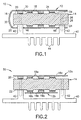
- FIG. 1 there is shown a partial cross-sectional view of an assembly 10 incorporating features of the present invention.
- the present invention will be described with reference to the embodiments shown in the drawings, it should be understood that the present invention can be embodied in many alternate forms of embodiments.
- any suitable size, shape of type of elements or materials could be used.
- the assembly 10 generally comprises a printed circuit board 12 and a first heat transfer member 14.
- the printed circuit board 12 generally comprises a flexible circuit member 16 and electronic components 18.
- the flexible circuit member 16 comprises a flexible substrate and electrical lead lines on the substrate.
- the printed circuit board could have a rigid substrate.
- the electronic components 18 can comprise any suitable type of electronic component, such as semiconductor chips.
- the first heat transfer member 14 generally comprises an anodized aluminum plate. However, other types of materials and/or shapes could be provided.
- the plate 14 has two opposite sides 20, 22 which include raised mounting surfaces 24.
- the plate 14 also comprises holes 26 for fasteners 28.
- the printed circuit board 12 is mounted to the plate 14 in order to remove heat from the electronic components 18.
- the electronic components 18 can generate heat during operation. Heat can decrease the working life of the printed circuit board 12.
- the assembly 10 could also be used in an environment which generates heat, such as in an engine compartment of an automobile. Thus, by providing the printed circuit board with the plate 14, heat can be removed from the electronic components 18 to increase the reliability and the working life of the printed circuit board 12; especially from heat peaks or spikes.
- the electronic components 18 are mounted to a first side 30 of the flexible circuit member 16. Additional electronic components could also be mounted to the opposite side of flexible circuit member.
- the flexible circuit member 16 is bent at area 32 to form a general U-shape. Top sides of the electronic components 18 are mounted to the two sides 20, 22 of the plate 14 by suitable means, such as thermally conductive adhesive 34. Alternative or additional means could be used to mount the components 18 onto the plate 14. Not all the components 18 have the same height. Thus, the raised mounting surfaces 24 help to compensate for the height differences. Because the circuit member 16 is flexible, the heights of the raised surfaces 24 need not be precise. The circuit member 16 can flex to accommodate small height mismatches. Thus, the plate 14 does not need to be manufactured to overly exact specifications and can, therefore, be manufactured in an inexpensive and fast automated process. The attachment of the printed circuit board 12 to the plate 14 can, thus, also be accomplished in an inexpensive and fast process.
- the assembly 10 further comprises a second heat transfer plate 40.
- the second heat transfer plate 40 is also comprised of a thermally conductive material, such as cast aluminum.
- the second plate 40 has mounting legs 42 and heat transfer cooling fins 44.
- the flexible circuit member 16 has holes 46.
- the legs 42 pass through the holes 46 and are attached to the first plate 14 by the fasteners 28. Thus, heat can transfer from the first plate 14, through the legs 42, to the fins 44 for removal to the surrounding air.
- the first plate 14 could have mounting posts which pass through the holes 46 in the circuit member 16.
- the second plate 40 need not be provided, such as when the first plate 14 has integral cooling fins.
- the legs 42 could extend around the outside perimeter of the printed circuit board 12 such that the holes 46 need not be provided.
- the assembly 50 generally comprises the first plate 14, the second plate 40, and two printed circuit boards 12a and 12b.
- the two printed circuit boards 12a, 12b are mounted on the opposite sides 20, 22 of the first plate 14, respectively.
- the circuit members 16a, 16b of the boards 12a, 12b have flexible substrates, but they could have rigid substrates.
- the legs 42 pass by the side perimeter of the lower board 12b rather than through holes.
- the electronic components 18a, 18b are mounted on the respective sided 20, 22 for heat transfer.
- the present invention allows a sub-assembly to be created in which a heat transfer element is sandwiched between a folded printed circuit board or two printed circuit boards.
- the heat transfer element could be attached to a radiator, such as fins 44.
- the radiator could be insert molded in a plastic box, such as disclosed in U.S. patent application No. 09/270,552 , entitled “ " (Attorney) Docket No. 611-008456-US (PAR) filed the same date as the present U.S. application) which is hereby incorporated by reference in its entirety.
- the use of a flexible circuit member reduces co-planarity problems between components 18 and the heat sink plate 14.
- the printed circuit board(s) could be mounted to two sides of the first heat transfer member which are not opposite sides.
- the printed circuit board(s) could be mounted on more that two side of the first heat transfer member.
- the printed circuit board(s) could be mounted on only one side of the first heat transfer member. If the printed circuit board(s) is/are bent to be located on more than one side of the first heat transfer member, the board(s) could have any suitable shape including an L-shape.
- all of the electronic components 18 need not be mounted onto the surface of the first heat transfer member.
Landscapes
- Physics & Mathematics (AREA)
- Thermal Sciences (AREA)
- Engineering & Computer Science (AREA)
- Microelectronics & Electronic Packaging (AREA)
- Cooling Or The Like Of Semiconductors Or Solid State Devices (AREA)
- Cooling Or The Like Of Electrical Apparatus (AREA)
Applications Claiming Priority (2)
| Application Number | Priority Date | Filing Date | Title |
|---|---|---|---|
| US09/268,808 US6154367A (en) | 1999-03-16 | 1999-03-16 | Heat sink for printed circuit board |
| US268808 | 2002-10-09 |
Publications (2)
| Publication Number | Publication Date |
|---|---|
| EP1037518A2 true EP1037518A2 (de) | 2000-09-20 |
| EP1037518A3 EP1037518A3 (de) | 2001-02-28 |
Family
ID=23024570
Family Applications (1)
| Application Number | Title | Priority Date | Filing Date |
|---|---|---|---|
| EP00104401A Withdrawn EP1037518A3 (de) | 1999-03-16 | 2000-03-02 | Kühlkörper für eine Leiterplatte |
Country Status (2)
| Country | Link |
|---|---|
| US (1) | US6154367A (de) |
| EP (1) | EP1037518A3 (de) |
Cited By (2)
| Publication number | Priority date | Publication date | Assignee | Title |
|---|---|---|---|---|
| FR2818491A1 (fr) * | 2000-12-19 | 2002-06-21 | Siemens Ag | Dispositif de refroidissement pour circuit electronique et procede de realisation de ce dispositif |
| CN112888148A (zh) * | 2021-01-12 | 2021-06-01 | 宁化宽信科技服务有限公司 | 一种印刷电路板 |
Families Citing this family (7)
| Publication number | Priority date | Publication date | Assignee | Title |
|---|---|---|---|---|
| US6236565B1 (en) * | 2000-06-15 | 2001-05-22 | Mark G. Gordon | Chip stack with active cooling system |
| TW573458B (en) * | 2003-06-09 | 2004-01-21 | Quanta Comp Inc | Functional module having built-in heat dissipation fins |
| JP5179746B2 (ja) * | 2006-11-22 | 2013-04-10 | 京セラ株式会社 | 携帯端末装置 |
| JP4325687B2 (ja) * | 2007-02-23 | 2009-09-02 | 株式会社デンソー | 電子装置 |
| RU2688581C1 (ru) * | 2018-06-18 | 2019-05-21 | Юрий Борисович Соколов | Способ изготовления трехмерного электронного модуля с высокой плотностью размещения компонентов и устройство |
| US11452198B2 (en) * | 2019-07-25 | 2022-09-20 | Borgwarner, Inc. | Thermally insulated printed circuit board |
| JP7444007B2 (ja) * | 2020-09-24 | 2024-03-06 | 株式会社オートネットワーク技術研究所 | 基板ユニット |
Family Cites Families (11)
| Publication number | Priority date | Publication date | Assignee | Title |
|---|---|---|---|---|
| US3766439A (en) * | 1972-01-12 | 1973-10-16 | Gen Electric | Electronic module using flexible printed circuit board with heat sink means |
| US4561011A (en) * | 1982-10-05 | 1985-12-24 | Mitsubishi Denki Kabushiki Kaisha | Dimensionally stable semiconductor device |
| DE3627372C3 (de) * | 1986-08-12 | 1994-04-14 | Loewe Opta Gmbh | Anordnung, bestehend aus einer Leiterplatte, einem Kühlkörper und zu kühlenden elektronischen Bauelementen |
| DE58902852D1 (de) * | 1988-05-05 | 1993-01-14 | Siemens Nixdorf Inf Syst | Anordnung zur konvektiven kuehlung von elektronischen bauelementen, insbesondere von integrierten halbleiterschaltungen. |
| US4849856A (en) * | 1988-07-13 | 1989-07-18 | International Business Machines Corp. | Electronic package with improved heat sink |
| US5050039A (en) * | 1990-06-26 | 1991-09-17 | Digital Equipment Corporation | Multiple circuit chip mounting and cooling arrangement |
| US5218516A (en) * | 1991-10-31 | 1993-06-08 | Northern Telecom Limited | Electronic module |
| US5402313A (en) * | 1993-05-21 | 1995-03-28 | Cummins Engine Company, Inc. | Electronic component heat sink attachment using a canted coil spring |
| US5831828A (en) * | 1993-06-03 | 1998-11-03 | International Business Machines Corporation | Flexible circuit board and common heat spreader assembly |
| US5768104A (en) * | 1996-02-22 | 1998-06-16 | Cray Research, Inc. | Cooling approach for high power integrated circuits mounted on printed circuit boards |
| US5812375A (en) * | 1996-05-06 | 1998-09-22 | Cummins Engine Company, Inc. | Electronic assembly for selective heat sinking and two-sided component attachment |
-
1999
- 1999-03-16 US US09/268,808 patent/US6154367A/en not_active Expired - Fee Related
-
2000
- 2000-03-02 EP EP00104401A patent/EP1037518A3/de not_active Withdrawn
Cited By (2)
| Publication number | Priority date | Publication date | Assignee | Title |
|---|---|---|---|---|
| FR2818491A1 (fr) * | 2000-12-19 | 2002-06-21 | Siemens Ag | Dispositif de refroidissement pour circuit electronique et procede de realisation de ce dispositif |
| CN112888148A (zh) * | 2021-01-12 | 2021-06-01 | 宁化宽信科技服务有限公司 | 一种印刷电路板 |
Also Published As
| Publication number | Publication date |
|---|---|
| EP1037518A3 (de) | 2001-02-28 |
| US6154367A (en) | 2000-11-28 |
Similar Documents
| Publication | Publication Date | Title |
|---|---|---|
| US5272599A (en) | Microprocessor heat dissipation apparatus for a printed circuit board | |
| US11497143B2 (en) | Mechanically flexible cold plates for low power components | |
| US6055158A (en) | Electronic component heat sink assembly | |
| US5077638A (en) | Heat sink for an electric circuit board | |
| US5930114A (en) | Heat sink mounting assembly for surface mount electronic device packages | |
| US6269863B1 (en) | Integrated processor mounting mechanism and heat sink | |
| JP3336090B2 (ja) | 集積回路の熱を消散させる装置及び方法 | |
| US7019976B1 (en) | Methods and apparatus for thermally coupling a heat sink to a circuit board component | |
| US6337796B2 (en) | Semiconductor device mount structure having heat dissipating member for dissipating heat generated from semiconductor device | |
| JPH06209174A (ja) | 放熱器 | |
| US6950310B2 (en) | System and method for self-leveling heat sink for multiple height devices | |
| US20010050844A1 (en) | Structure for mounting radiating plate | |
| JPH08204078A (ja) | ヒートシンクアッセンブリー | |
| WO2002035901A1 (en) | Apparatus for providing heat dissipation for a circuit element | |
| EP1047293A2 (de) | Kühlkörperbefestigung und Verfahren | |
| US6154367A (en) | Heat sink for printed circuit board | |
| US6188131B1 (en) | Clip for retaining a heatsink onto an electronic component | |
| JPS58176959A (ja) | 放熱フインの装着構造 | |
| EP1113495B1 (de) | Oberflächenmontierter Leistungstransistor mit Kühlkörper | |
| JP3264780B2 (ja) | 回路ユニットの放熱装置 | |
| JPH11312770A (ja) | 薄型icの放熱フィン | |
| US6219248B1 (en) | Heat sink alignment apparatus and method | |
| JPH0559894U (ja) | 発熱電子部品の放熱構造 | |
| CN210958936U (zh) | 一种散热效率高的电路基板 | |
| JP3318511B2 (ja) | カード型半導体装置の実装構造 |
Legal Events
| Date | Code | Title | Description |
|---|---|---|---|
| PUAI | Public reference made under article 153(3) epc to a published international application that has entered the european phase |
Free format text: ORIGINAL CODE: 0009012 |
|
| AK | Designated contracting states |
Kind code of ref document: A2 Designated state(s): AT BE CH CY DE DK ES FI FR GB GR IE IT LI LU MC NL PT SE |
|
| AX | Request for extension of the european patent |
Free format text: AL;LT;LV;MK;RO;SI |
|
| PUAL | Search report despatched |
Free format text: ORIGINAL CODE: 0009013 |
|
| AK | Designated contracting states |
Kind code of ref document: A3 Designated state(s): AT BE CH CY DE DK ES FI FR GB GR IE IT LI LU MC NL PT SE |
|
| AX | Request for extension of the european patent |
Free format text: AL;LT;LV;MK;RO;SI |
|
| 17P | Request for examination filed |
Effective date: 20010820 |
|
| AKX | Designation fees paid |
Free format text: AT BE CH CY DE DK ES FI FR GB GR IE IT LI LU MC NL PT SE |
|
| STAA | Information on the status of an ep patent application or granted ep patent |
Free format text: STATUS: THE APPLICATION IS DEEMED TO BE WITHDRAWN |
|
| 18D | Application deemed to be withdrawn |
Effective date: 20031001 |