EP1037397B1 - Mehrfrequenz-Funkübertragungsvorrichtung und zugehöriges Verfahren - Google Patents
Mehrfrequenz-Funkübertragungsvorrichtung und zugehöriges Verfahren Download PDFInfo
- Publication number
- EP1037397B1 EP1037397B1 EP20000400686 EP00400686A EP1037397B1 EP 1037397 B1 EP1037397 B1 EP 1037397B1 EP 20000400686 EP20000400686 EP 20000400686 EP 00400686 A EP00400686 A EP 00400686A EP 1037397 B1 EP1037397 B1 EP 1037397B1
- Authority
- EP
- European Patent Office
- Prior art keywords
- frequency
- receiver
- frequencies
- signal
- listening
- Prior art date
- Legal status (The legal status is an assumption and is not a legal conclusion. Google has not performed a legal analysis and makes no representation as to the accuracy of the status listed.)
- Expired - Lifetime
Links
- 230000005540 biological transmission Effects 0.000 title claims description 29
- 238000000034 method Methods 0.000 title claims description 10
- 238000012545 processing Methods 0.000 claims description 12
- 238000005259 measurement Methods 0.000 claims description 6
- 230000008569 process Effects 0.000 claims description 3
- 238000010586 diagram Methods 0.000 description 10
- 230000008901 benefit Effects 0.000 description 5
- 238000004891 communication Methods 0.000 description 4
- 238000001514 detection method Methods 0.000 description 3
- 230000006870 function Effects 0.000 description 3
- 238000009434 installation Methods 0.000 description 3
- 230000009467 reduction Effects 0.000 description 3
- 241000269400 Sirenidae Species 0.000 description 2
- 239000000969 carrier Substances 0.000 description 2
- 230000008859 change Effects 0.000 description 2
- 239000000779 smoke Substances 0.000 description 2
- 230000003595 spectral effect Effects 0.000 description 2
- 230000004913 activation Effects 0.000 description 1
- 230000001419 dependent effect Effects 0.000 description 1
- 238000005265 energy consumption Methods 0.000 description 1
- 238000012986 modification Methods 0.000 description 1
- 230000004048 modification Effects 0.000 description 1
- 238000012544 monitoring process Methods 0.000 description 1
- 230000001681 protective effect Effects 0.000 description 1
- 239000004065 semiconductor Substances 0.000 description 1
- 230000008054 signal transmission Effects 0.000 description 1
- 238000010897 surface acoustic wave method Methods 0.000 description 1
- 230000001960 triggered effect Effects 0.000 description 1
Images


Classifications
-
- H—ELECTRICITY
- H04—ELECTRIC COMMUNICATION TECHNIQUE
- H04B—TRANSMISSION
- H04B7/00—Radio transmission systems, i.e. using radiation field
- H04B7/02—Diversity systems; Multi-antenna system, i.e. transmission or reception using multiple antennas
- H04B7/04—Diversity systems; Multi-antenna system, i.e. transmission or reception using multiple antennas using two or more spaced independent antennas
- H04B7/08—Diversity systems; Multi-antenna system, i.e. transmission or reception using multiple antennas using two or more spaced independent antennas at the receiving station
- H04B7/0802—Diversity systems; Multi-antenna system, i.e. transmission or reception using multiple antennas using two or more spaced independent antennas at the receiving station using antenna selection
- H04B7/0817—Diversity systems; Multi-antenna system, i.e. transmission or reception using multiple antennas using two or more spaced independent antennas at the receiving station using antenna selection with multiple receivers and antenna path selection
- H04B7/082—Diversity systems; Multi-antenna system, i.e. transmission or reception using multiple antennas using two or more spaced independent antennas at the receiving station using antenna selection with multiple receivers and antenna path selection selecting best antenna path
-
- H—ELECTRICITY
- H04—ELECTRIC COMMUNICATION TECHNIQUE
- H04B—TRANSMISSION
- H04B7/00—Radio transmission systems, i.e. using radiation field
- H04B7/02—Diversity systems; Multi-antenna system, i.e. transmission or reception using multiple antennas
- H04B7/12—Frequency diversity
Definitions
- the invention is in the field of signal transmission for transmitting information or messages. It relates more particularly to so-called "wireless" devices, for which the information or messages are transmitted, for example between detectors and a central, by radio.
- the remote control by radio link lighting, alarm, home automation applications usually use a single carrier frequency to transmit the information. Transmissions of radio messages are then effected by means of a high frequency signal (called a single carrier), modulated by a signal representing the information to be transmitted.
- a single carrier a high frequency signal
- the disadvantage of this type of transmission comes from the fact that a disturbance on said carrier frequency may modify the modulating signal and make it unusable.
- the aims of the present invention are to overcome the aforementioned drawbacks, and to provide a system for improving the quality of the radio link, particularly in case of external disturbance, with reduced consumption, and at low cost.
- a radio-based information transmission device comprising at least one transmitter adapted to emit a signal on at least two frequencies, alternately and / or simultaneously, and a receiver characterized in that the device comprises means for order listening by the receiver of only one of the frequencies of the transmitters at a time, and to switch from the listening of a frequency to listening of another frequency according to a criterion of quality and / or conformity of predetermined received signal, said means (28) being adapted to activate and supply energy at a given time with a single reception channel of a said frequency.
- a central processing unit 1 receives information from a number of detectors 2 installed at various points of the building to be monitored, and for example detectors of movement, opening, smoke, light, flood, device failure.
- the central processing unit 1 also receives instructions from a remote control 3 or an equivalent device, for example wall (not shown here).
- the processing unit 1 determines, according to an internal logic, the eventual activation of an alarm siren 4 or a telephone transmitter 5, or other devices adapted to the situation detected.
- the information flows between the detectors 2, the remote control 3 and the central processing unit 1, as well as between the central processing unit 1 and the alarm sirens 4 and / or telephone transmitter 5, are in a protective application wireless, made by radio links. Each of these links is then capable of accommodating a communication device according to the invention.
- the detectors 2 typically each comprise an emitter according to the invention, while the central processing unit 1 and the alarm sirens 4 and telephone transmitter 5 each comprise a transmitting device according to the invention.
- Each detector 2 is simply equipped with a transmitter (for reasons of cost and power consumption, since these detectors operate on batteries), and therefore can not receive information or questions from the central processing unit 1, it transmits information at regular intervals (for example every hour) on its state (battery still correctly charged, etc.), as well as, if necessary, information at the moment of detection (for example smoke detection), for an appropriate processing by the central processing unit 1. It is understood that in such an arrangement, the detectors may accidentally transmit their messages simultaneously, despite the brevity of these messages, and a repetition of the transmission of messages is therefore planned. These provisions are of a classical nature and will not be detailed here.
- the principle of multi-frequency radio communication explained below uses, for example, the exploitation of the harmonics of a frequency generated by a single oscillator in order to transmit different resulting carrier frequencies.
- the different frequencies used are multiples of the frequency of the oscillator used.
- the N transmission channels created depend on the oscillator used.
- this method combines the reliability of the radio link with a reduction in the cost of the product.
- the advantage of this method is the reduction of the number of oscillators, and therefore the reduction of the cost of the device.
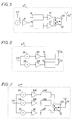
- the functional diagram of a transmitter 6 using this principle is illustrated by the figure 2 . It is a transmitter type diversity issue, that is to say, transmitting the same message on more than one frequency.
- Said transmitter 6 comprises an oscillator 7, optionally advantageously controlled, for example by a surface acoustic wave resonator (SAW), a phase-locked loop (PLL), not shown on the figure 2 . It oscillates at a frequency f1.
- SAW surface acoustic wave resonator
- PLL phase-locked loop
- a modulating signal SM representing information to be transmitted is applied to the modulation input (the information to be transmitted being typically a message formed by a succession of binary data).
- An amplitude modulation of "all-or-nothing" type in English OOK for "On-Off Keying" is used in the device described here by way of non-limiting example.
- the signal emanating from the oscillator 7 is optionally advantageously amplified by an amplifier 8 of conventional type, known to those skilled in the art.
- the optionally amplified signal is then filtered, on a first channel, by a band-pass filter 9 and, on a second channel, by a band-pass filter 10, respectively centered on frequencies fN and fM, which are harmonics of the fundamental frequency f1 of the oscillator 7.
- the frequencies f1 and f2 can advantageously belong to one of the 434 MHz band and the other to the 868 MHz band.
- the filtered signals from the bandpass filters 9, 10 are amplified by amplifiers 11, 12, of conventional type.
- the advantage of this system is to be able to realize a transmission on several frequencies with a single oscillator; the transmission channels thus created being dependent on the single oscillator used.
- the transmitting device therefore uses in the example described here two transmission channels at 434 MHz and 868 MHz respectively.
- a receiver 15 In reception, a receiver 15 according to the invention must be able to demodulate the two frequencies fN and fM not simultaneously. With such a receiver 15, the frequency of demodulation (fN or fM) of the signal is alternately chosen, and consumption is advantageously reduced compared to a conventional simultaneous reception system.
- Such a receiver 15 is described, by way of non-limiting example, with reference to the figure 3 . It can be seen that said receiver combines two conventional reception channels, illustrated at the top and at the bottom of the figure 3 only one of the two chains is active and energized at a given time.
- the signals emanating from the antennas 13 and 14 of the transmitter 6 are received by two antennas 16, 17, respectively for the frequencies f1 and f2, of the receiver 15.
- the signal coming from the antenna 16 (respectively 17) is filtered in a bandpass filter 18 (respectively 19), centered on the frequency f1 (respectively f2), then attacks an amplifier 20 (21 respectively).
- a bandpass filter 18 (respectively 19), centered on the frequency f1 (respectively f2), then attacks an amplifier 20 (21 respectively).
- the signal enters a mixer 22 (respectively 23), in which it is combined with a signal emanating from a local oscillator 24 (respectively 25) set on a frequency f Ol1 ( Ol2 ).
- the local receiving oscillator 24 oscillates f1 for example at a frequency f ol 1 equal to the difference f1-fi 1, 1 fi being an intermediate frequency to the frequency f1.
- the receiving local oscillator 25 oscillates at a frequency f2 ol f 2 equal to the difference f1 -fi 2, 2 fi being an intermediate frequency to the frequency f2.
- the frequency signal fi 1 (fi 2 ) enters a demodulator 26 (respectively 27).
- This device is of conventional type, and its various components are well known to those skilled in the art.
- the demodulated output (in the form of binary data) from the demodulator 26 enters a microcontroller 28 of conventional type. This one allows among others to manage the feeding of the different active parts of the receiver 15, and therefore not to supply energy to one of the reception chains when the other is only active.
- a device provided with an inverter 29, controlled by a command C issued by the microcontroller 28, is intended to supply one or the other of the reception channels. It is understood that the microcontroller 28 then actually performs a switch function for choosing between the two reception channels, according to programmable criteria and modifiable if necessary.
- the received data are processed in a conventional manner.
- transceiver also called transceiver
- This diagram shows the oscillator 7 of frequency f1, the amplifier 8, the bandpass filters 9 and 10 centered on frequencies N.f1 (fN) and M.f1 (fM), followed by amplifiers 11 and 12, able to be controlled by non-detailed devices.
- These amplifiers 11, 12 drive function switches 31, 32, of conventional type, the function of which is to select between the transmission mode and the reception mode for the transceiver device. In transmission mode, these switches send the signals from the amplifiers 11, 12 to the antennas 13, 14.
- the same antennas 13, 14 receive incoming signals, and transmit them to bandpass filters 18, 19, centered on f1 and f2.
- the device provided with the inverter 29 supplies one or the other of the reception channels, centered on either f1 or f2, according to a criterion of choice of channel based on the quality of reception of the signal and detailed below.
- reception chains are then in all respects identical to what has been described above.
- the method of transmitting information I o (such as a signal with at least two states) supplied to the input of transmission means and exploitable at the output of reception means, consists according to the invention to exploit the harmonics N.f1 and Mf1 of the oscillator 7 of frequency f1 (M and N being two different positive integers, each greater than or equal to 1), and in the preferred embodiment, to transmit these two frequencies N.f1 and M.f1 according to a classical technique of diversity, and to receive them also in diversity.
- M and N being two different positive integers, each greater than or equal to 1
- the device described by way of example operates using an amplitude modulation of "all-or-nothing" type (in English OOK for "On-Off Keying"): the modulating signal representing information to transmit is applied to the modulation input ( figure 2 ).
- the information to be transmitted is typically a message formed of a succession of binary data.
- Each transmitter 6 then transmits a frame which contains several times a calibrated portion known to the receiver, which is advantageously an identifier of the transmitter, followed by the actual message of the transmitter.
- a detector 2 comprising a transmitter 6 as described transmits to the processing center 1 its identity as a calibrated message, before sending a detection message or actual state.
- Each frame is transmitted by a detector 2 given several times, separated by time intervals according to a predetermined logic (for example two transmissions separated by a randomly chosen time in a given range), to further increase the chances of passing the message. at the central processing station 1.
- a predetermined logic for example two transmissions separated by a randomly chosen time in a given range
- reception two reception channels centered on the two frequencies transmitted simultaneously are activated not simultaneously, according to a criterion of quality and / or received signal conformity, which criterion is stored in a memory of the microcontroller 28 and calculated by this microcontroller 28.
- This method makes it possible to choose the received reception frequency, N.f1 or Mf1, the receiver 15 being able to demodulate the frequencies N.f1 and Mf1 not simultaneously.
- the receiver 15 (for example that of the central processing unit 1) is normally in "off" mode to consume the minimum of energy, and switches to normal listening mode at regular intervals for short periods of time. periods of time.
- the receiver listens to only one of the two frequencies (for example f1). If no signal arrives on this frequency (according to a measurement criterion of the power received on the listened frequency, below a predetermined power threshold), the receiver 15 "goes back" very quickly.
- the receiver 15 maintains its listening for a sufficient time to ensure that at least one calibrated part (the number of correct receptions required being programmable and stored in the microcontroller 28) arrives on the receiver .
- the receiver 15 recognizes a calibrated portion (identifying a detector whose identity has been previously stored), it maintains its listening on this single frequency to be able to demodulate the signal and receive the message from said identified detector 2.
- the calibrated part recognition criterion comprises a comparison of the received signal with a series of detector identifiers 2 stored in the microcontroller 28. An error rate calculation for this identified calibrated message is then possible, and the passage below a predetermined threshold (number of right / wrong bits) causes the channel change listened.
- the receiver 15 In the case where the receiver 15 does not recognize the calibrated part, the signal being of poor quality, for example due to disturbances, the receiver 15 switches on listening to the other frequency (on the order of the microcontroller 28, which causes a change of state of the command C).
- the device according to the invention has both the advantage of providing redundancy in the emission of the signal by the simultaneous emission on two distant frequencies, and moreover avoids an excessive increase of the energy consumption, since the second frequency is only heard when the first frequency is too much disturbed, and when the "active" elements of the second reception channel are powered only when listening to said second frequency.
- a switch 30 is added at the output of the amplifiers 11, 12. This switch 30 is controlled by an E command. output, the switch 30 is connected to a transmitting antenna 13 '.
- the command E ensures the transmission of a message on the first frequency f1, then the re-transmission of this same message on the second frequency f2.
- the control of the switch 30 may be a signal from a microcontroller (not shown) which holds the switch 30 in one position the time of a message, then in the second position the time of a second message, and so on.
- the single oscillator 7 is replaced by two oscillators 7A, 7B, followed by amplifiers 8A, 8B, the remainder of the transmitter 6 being substantially unchanged.
- the modulation is for example of the OOK type. It is clear that this device can be extended to more than two frequencies very simply.
- the figure 7 illustrates yet another variant transmitter 6 ', in which three transmission chains are provided; In each transmission channel, an oscillator 7A, 7B, 7C, an amplifier 8A, 8B, 8C, and a bandpass filter 9A, 9B, 9C are recognized.
- a switch 30 controlled by a command E allows sending to the antenna 13 is signals from the first two transmission chains (7A, 8A, 9A, 7B, 8B, 9B), or the third transmission channel (7C, 8C, 9C).
- This device then transmits a message first on two first frequencies, then a repetition of the message on a third frequency. These frequencies can naturally be harmonics of the same fundamental frequency.
- a receiver variant 15 'illustrated by the figure 8 only one receiving antenna 16 'is used. It is followed by a switch 31 (also controlled by the microcontroller 28). This switch 31 sends the received signal either on a first reception channel centered on a first frequency f1, or on a second reception channel centered on a second frequency f2.
- the receiver device comprises a local reception oscillator 24, of fundamental frequency f ol1 and a local reception oscillator 25, of fundamental frequency f ol2 , these frequencies being chosen such that the intermediate frequency f i is identical for the reception of a signal to f1 and that of a signal to f2.
- the advantage here is related to the use of a single demodulator.
- receiver 15 is illustrated by the figure 9 .
- the first part of the receiver 15 is identical to the receiver 15 'illustrated by the figure 8 .
- the signal is received by the antenna 16 'and then switched on one of two channels: the first channel selects the frequency f1 via a filter 18 associated with an amplifier 20, and the second the frequency f2 via a filter 19 and an amplifier 21.
- the signal enters a single mixer 22 ', in which it is combined with a frequency signal either f1 or f2 resulting from a frequency signal f1 generated by an oscillator unique 32 can advantageously integrate a conventional amplifier element, not detailed here.
- the signal emanating from the oscillator 32 is directed on two channels.
- the first channel selects the frequency f1 via a filter 33 associated with an amplifier 35, and the second, the frequency f2 via a filter 34 associated with an amplifier 36.
- a switch 37 for example a semiconductor, selects the reception frequency f1 or f2 entering the mixer 22 '.
- the frequency of the local reception oscillator being identical to the received carrier frequency, characterized by a low frequency signal at the output of the mixer 22 ', attacking a reset system form 26 followed by the microcontroller 28, which controls according to the channel selection criterion described above, the commands (C and its inverse) supply of the various receiving elements, and the switches 31 and 37.
- the receiver 15 chooses a reception frequency among all the frequencies used. In this way, if one of the transmission channels is disturbed, it is possible to recover the signal containing the information from another undisturbed channel by positioning the receiver listening on this other undisturbed channel. In the case of three frequencies, if the second is also disturbed, the receiver switches to the third frequency.
- the frequencies chosen may be any harmonics of the same frequency f1.
- the modulation mode of the signal can be arbitrary, for example modulation of amplitude, frequency, etc.
- a calibrated portion when a calibrated portion is detected by the receiver 15 on the frequency currently being listened to, said receiver also listens for the other frequency for a short time, and compares the quality of received signal on these two frequencies, then choosing to listen to the frequency that provides the best signal level.
- the transmitting and / or receiving antenna is advantageously formed of two sections of identical length (quarter of the wavelength of the frequency 2f1), separated by a parallel circuit L, C equivalent to an open circuit for 2f1 and a short circuit for the frequency f1.
- the figure 10b illustrates a similar principle in the case of three frequencies with three sections of respective lengths L 1/2 , L 1/2 and L 1 , thus determining an antenna adapted to the frequencies 4f1, 2f1 and f1.
Landscapes
- Engineering & Computer Science (AREA)
- Computer Networks & Wireless Communication (AREA)
- Signal Processing (AREA)
- Radio Transmission System (AREA)
Claims (14)
- Vorrichtung zur Übertragung von Informationen über Funk, enthaltend mindestens einen Sender (6), der dazu angepasst ist, ein Signal auf mindestens zwei Frequenzen (fN, fM) alternativ und/oder gleichzeitig auszusenden, und einen Empfänger (15), dadurch gekennzeichnet, dass die Vorrichtung Mittel (28) enthält zur Steuerung des Abhörens jeweils nur einer der Frequenzen des Senders (6) durch den Empfänger (15) und um gemäß eines vorbestimmten Kriteriums der Qualität und/oder der Konformität des empfangenen Signals vom Abhören einer Frequenz zum Abhören einer anderen Frequenz überzugehen, wobei die genannten Mittel (28) dazu angepasst sind, zu einem gegebenen Moment nur einen Empfangs-Kanal einer bestimmten Frequenz zu aktivieren und mit Energie zu versorgen.
- Vorrichtung zur Übertragung nach Anspruch 1, dadurch gekennzeichnet, dass sie Mittel enthält, um in regelmäßigen Intervallen mit einer Länge, die geringer ist, als die Dauer eines Datenblocks, in den normalen Abhör-Modus einer Frequenz überzugehen, um einen Pegel der Leistung zu messen, die auf der abgehörten Frequenz empfangen wird, um diesen Messwert mit einer vorbestimmten Leistungs-Schwelle zu vergleichen, und um in einen "ausgeschalteten" Modus überzugehen, wenn der Pegel geringer ist als die Leistungs-Schwelle.
- Vorrichtung zur Übertragung nach einem beliebigen der Ansprüche 1 bis 2, dadurch gekennzeichnet, dass das Kriterium für den Wechsel der durch den Empfänger (15) abgehörten Frequenz ein Kriterium des Verhältnisses Signal/Rauschen zwischen dem empfangenen Signal und einem zuvor gespeicherten Rausch-Pegel enthält, das geringer ist, als eine vorbestimmte Schwelle.
- Vorrichtung zur Übertragung nach einem beliebigen der Ansprüche 1 bis 3, dadurch gekennzeichnet, dass das Kriterium für den Wechsel der durch den Empfänger (15) abgehörten Frequenz ein Kriterium der (Anzahl der korrekten Bits / Anzahl der falschen Bits) beim Empfang eines vorbestimmten, kalibrierten Teils des Signals, das durch die Sender (6) auf der abgehörten Frequenz ausgesendet wird, enthält, das geringer ist als eine vorbestimmte Schwelle.
- Vorrichtung nach einem beliebigen der Ansprüche 1 bis 4, dadurch gekennzeichnet, dass der Sender (6) auf mehreren Frequenzen (fN, fM) aussendet, die ausgehend von einem einzigen Oszillator (7) erzeugt werden.
- Vorrichtung nach Anspruch 5, dadurch gekennzeichnet, dass die Sende-Frequenzen (fN, fM) der Sender (6) die Grund-Frequenz (f1) des Oszillators (7) und die erste Oberschwingung (f2) dieses Oszillators sind.
- Vorrichtung nach Anspruch 6, dadurch gekennzeichnet, dass die erste Frequenz aus dem 434 MHz-Band gewählt ist und die zweite Frequenz aus dem 868 MHz-Band.
- Vorrichtung nach einem beliebigen der Ansprüche 1 bis 7, dadurch gekennzeichnet, dass mindestens ein Sender (6) von der Art der Aussendung mit Frequenz-Diversity ist.
- Vorrichtung nach einem beliebigen der Ansprüche 1 bis 8, dadurch gekennzeichnet, dass ein Sender (6) und ein Empfänger (15) in einem einzigen Gerät zusammengefasst sind.
- Vorrichtung nach Anspruch 9, dadurch gekennzeichnet, dass sie Funktions-Umschalter (31, 32) enthält, die dazu angepasst sind, die Auswahl des Sende- oder Empfangs-Modus der Vorrichtung zu ermöglichen.
- Vorrichtung nach einem beliebigen der Ansprüche 1 bis 5, dadurch gekennzeichnet, dass die Anzahl der verwendeten Frequenzen größer oder gleich drei ist.
- Vorrichtung nach einem beliebigen der Ansprüche 1 bis 11, dadurch gekennzeichnet, dass mindestens ein Sender (6) oder ein Empfänger (15) eine Antenne enthält, die aus mehreren, durch Tiefpass-Filter getrennten Abschnitten geformt ist.
- Alarm-System, mindestens einen Detektor (2) enthaltend, der Nachrichten über ein Funk-Medium an eine Verarbeitungs-Zentrale (1) aussendet, dadurch gekennzeichnet, dass es eine Vorrichtung nach einem beliebigen der Ansprüche 1 bis 10 enthält.
- Verfahren zur Übertragung von Informationen über Funk zwischen mindestens einem Sender (6), der/die dazu angepasst ist/sind, ein Signal auf mindestens zwei Frequenzen (fN, fM), die den verschiedenen Sendern gemeinsam sind, alternativ oder gleichzeitig auszusenden, und einem Empfänger (15), dadurch gekennzeichnet, dass das Verfahren enthält:a) die Aussendung eines Signals durch den Sender (6) auf mindestens zwei Frequenzen (fN, fM) alternativ und/oder gleichzeitig,b) das Abhören jeweils nur einer der Frequenzen des Senders (6) durch den Empfänger (15),c) und den Übergang vom Abhören einer Frequenz zum Abhören einer anderen Frequenz gemäß eines vorbestimmten Kriteriums der Qualität und/oder der Konformität des empfangenen Signals, wobei jeweils nur ein Empfangs-Kanal einer genannten Frequenz aktiviert und versorgt wird.
Applications Claiming Priority (2)
| Application Number | Priority Date | Filing Date | Title |
|---|---|---|---|
| FR9903377 | 1999-03-18 | ||
| FR9903377A FR2791199B1 (fr) | 1999-03-18 | 1999-03-18 | Dispositif de transmission radio multifrequences |
Publications (2)
| Publication Number | Publication Date |
|---|---|
| EP1037397A1 EP1037397A1 (de) | 2000-09-20 |
| EP1037397B1 true EP1037397B1 (de) | 2008-02-27 |
Family
ID=9543349
Family Applications (1)
| Application Number | Title | Priority Date | Filing Date |
|---|---|---|---|
| EP20000400686 Expired - Lifetime EP1037397B1 (de) | 1999-03-18 | 2000-03-16 | Mehrfrequenz-Funkübertragungsvorrichtung und zugehöriges Verfahren |
Country Status (4)
| Country | Link |
|---|---|
| EP (1) | EP1037397B1 (de) |
| DE (1) | DE60038140T2 (de) |
| ES (1) | ES2301472T3 (de) |
| FR (1) | FR2791199B1 (de) |
Families Citing this family (3)
| Publication number | Priority date | Publication date | Assignee | Title |
|---|---|---|---|---|
| FR2904740B1 (fr) * | 2006-08-04 | 2010-05-21 | Lyonnaise Eaux France | Dispositif d'acquisition multi-voies pour transmetteurs radio. |
| US20120245845A1 (en) * | 2011-03-24 | 2012-09-27 | Honeywell International Inc. | Triple redundant rf link system |
| US8706058B2 (en) | 2011-03-24 | 2014-04-22 | Honeywell International Inc. | RF data transfer in a spherical cavity |
Family Cites Families (2)
| Publication number | Priority date | Publication date | Assignee | Title |
|---|---|---|---|---|
| GB2094102B (en) * | 1981-02-04 | 1984-06-27 | Philips Electronic Associated | Radio receiver suitable for use in a spaced carrier area coverage system |
| JPH05102898A (ja) * | 1991-08-07 | 1993-04-23 | Shiyoudenriyoku Kosoku Tsushin Kenkyusho:Kk | 高調波通信方式 |
-
1999
- 1999-03-18 FR FR9903377A patent/FR2791199B1/fr not_active Expired - Fee Related
-
2000
- 2000-03-16 ES ES00400686T patent/ES2301472T3/es not_active Expired - Lifetime
- 2000-03-16 EP EP20000400686 patent/EP1037397B1/de not_active Expired - Lifetime
- 2000-03-16 DE DE2000638140 patent/DE60038140T2/de not_active Expired - Fee Related
Also Published As
| Publication number | Publication date |
|---|---|
| FR2791199A1 (fr) | 2000-09-22 |
| EP1037397A1 (de) | 2000-09-20 |
| DE60038140T2 (de) | 2009-02-26 |
| FR2791199B1 (fr) | 2006-07-28 |
| DE60038140D1 (de) | 2008-04-10 |
| ES2301472T3 (es) | 2008-07-01 |
Similar Documents
| Publication | Publication Date | Title |
|---|---|---|
| EP1180301B1 (de) | Lokales kombiniertes telefon- und alarmsystem | |
| FR3084495A1 (fr) | Système passif d’entrée sans clé | |
| EP2832158A1 (de) | Verfahren zur verarbeitung des empfangs eines kommunikationssignals über einen funkkanal und zugehöriges verfahren zur verarbeitung der übertragung, vorrichtungen und computerprogramme | |
| FR3085241A1 (fr) | Systeme de surveillance de securite et noeud pour un tel systeme | |
| EP0717912A1 (de) | Verfahren zum langeren betrieb eines funkrufempfanger und empfanger hierzu | |
| EP1037397B1 (de) | Mehrfrequenz-Funkübertragungsvorrichtung und zugehöriges Verfahren | |
| EP3716242B1 (de) | Alarmsystem mit gesicherter funkfrequenzkommunikation | |
| FR2639167A1 (fr) | Procede et systeme de transmission d'un signal | |
| EP2605423B1 (de) | Satelliten Übertragungsanordnung mit Schaltung zwischen niedrig, mittel und hoher Datengeschwindigkeit entsprechend Interferenz Bedingungen. | |
| EP0013248B1 (de) | Hyperfrequenz-Fernmeldevorrichtung | |
| EP4209958A1 (de) | Nfc-vorrichtungserkennung | |
| FR3085243A1 (fr) | Systeme de surveillance de securite | |
| EP1453217B1 (de) | Verfahren zur Dämpfung des Einflusses von Interferenzen, die von Burstfunkübertragungssysteme generiert werden, auf UWB Kommunikationen | |
| FR3085245A1 (fr) | Systeme de surveillance de securite, noeud et unite centrale pour un tel systeme | |
| EP1583248B1 (de) | HF-Mehrbandempfänger mit Vorrichtung zur Reduzierung des Energieverbrauches | |
| CA2297797A1 (fr) | Objet portatif a communication sans contact suivant deux voies de communication, inductive et hertzienne | |
| FR3085244A1 (fr) | Systeme de surveillance de securite, noeud et unite centrale pour un tel systeme | |
| FR2951039A1 (fr) | Procede de configuration en emission d'un noeud de communication, produit programme d'ordinateur, moyen de stockage et nœud de communication correspondants. | |
| EP1859421B1 (de) | Mehrkanal-kinderüberwachungsvorrichtung und verfahren | |
| EP3769449A1 (de) | Verfahren zur drahtlosen kommunikation zwischen mindestens einem energieautarken gefahrenmeldeendgerät und einer kommunikationseinheit | |
| WO2025223818A1 (fr) | Système d'alarme avec un lien de communication de secours entre pairs | |
| EP2267933B1 (de) | Empfangsbestätigungsverfahren eines ferngesteuerten Systems von Hausgeräten | |
| EP2110969B1 (de) | Verfahren und Vorrichtung zur Überwachung von Objekten in einem vorgegebenen Bereich | |
| FR2745134A1 (fr) | Procede d'etablissement d'une communication entre des terminaux mobiles d'un reseau de radiocommunication numerique | |
| FR3080725A1 (fr) | Procede de communication sans-fil entre au moins un terminal de detection d'un risque autonome energetiquement et un organe communicant |
Legal Events
| Date | Code | Title | Description |
|---|---|---|---|
| PUAI | Public reference made under article 153(3) epc to a published international application that has entered the european phase |
Free format text: ORIGINAL CODE: 0009012 |
|
| AK | Designated contracting states |
Kind code of ref document: A1 Designated state(s): DE ES GB IT |
|
| AX | Request for extension of the european patent |
Free format text: AL;LT;LV;MK;RO;SI |
|
| 17P | Request for examination filed |
Effective date: 20010319 |
|
| AKX | Designation fees paid |
Free format text: DE ES GB IT |
|
| 17Q | First examination report despatched |
Effective date: 20040930 |
|
| RTI1 | Title (correction) |
Free format text: MULTIFREQUENCY RADIO TRANSMISSION DEVICE AND CORRESPONDING METHOD |
|
| GRAP | Despatch of communication of intention to grant a patent |
Free format text: ORIGINAL CODE: EPIDOSNIGR1 |
|
| RAP1 | Party data changed (applicant data changed or rights of an application transferred) |
Owner name: LEGRAND FRANCE |
|
| GRAS | Grant fee paid |
Free format text: ORIGINAL CODE: EPIDOSNIGR3 |
|
| GRAA | (expected) grant |
Free format text: ORIGINAL CODE: 0009210 |
|
| AK | Designated contracting states |
Kind code of ref document: B1 Designated state(s): DE ES GB IT |
|
| REG | Reference to a national code |
Ref country code: GB Ref legal event code: FG4D Free format text: NOT ENGLISH |
|
| REF | Corresponds to: |
Ref document number: 60038140 Country of ref document: DE Date of ref document: 20080410 Kind code of ref document: P |
|
| REG | Reference to a national code |
Ref country code: ES Ref legal event code: FG2A Ref document number: 2301472 Country of ref document: ES Kind code of ref document: T3 |
|
| PLBE | No opposition filed within time limit |
Free format text: ORIGINAL CODE: 0009261 |
|
| STAA | Information on the status of an ep patent application or granted ep patent |
Free format text: STATUS: NO OPPOSITION FILED WITHIN TIME LIMIT |
|
| 26N | No opposition filed |
Effective date: 20081128 |
|
| PGFP | Annual fee paid to national office [announced via postgrant information from national office to epo] |
Ref country code: ES Payment date: 20090304 Year of fee payment: 10 |
|
| PGFP | Annual fee paid to national office [announced via postgrant information from national office to epo] |
Ref country code: GB Payment date: 20090317 Year of fee payment: 10 |
|
| PGFP | Annual fee paid to national office [announced via postgrant information from national office to epo] |
Ref country code: IT Payment date: 20090319 Year of fee payment: 10 Ref country code: DE Payment date: 20090429 Year of fee payment: 10 |
|
| GBPC | Gb: european patent ceased through non-payment of renewal fee |
Effective date: 20100316 |
|
| PG25 | Lapsed in a contracting state [announced via postgrant information from national office to epo] |
Ref country code: DE Free format text: LAPSE BECAUSE OF NON-PAYMENT OF DUE FEES Effective date: 20101001 |
|
| PG25 | Lapsed in a contracting state [announced via postgrant information from national office to epo] |
Ref country code: IT Free format text: LAPSE BECAUSE OF NON-PAYMENT OF DUE FEES Effective date: 20100316 Ref country code: GB Free format text: LAPSE BECAUSE OF NON-PAYMENT OF DUE FEES Effective date: 20100316 |
|
| REG | Reference to a national code |
Ref country code: ES Ref legal event code: FD2A Effective date: 20111118 |
|
| PG25 | Lapsed in a contracting state [announced via postgrant information from national office to epo] |
Ref country code: ES Free format text: LAPSE BECAUSE OF NON-PAYMENT OF DUE FEES Effective date: 20100317 |