EP1037354B1 - Verfahren zum Betreiben eines elektromotorischen Antriebs für einen Aufzug und danach betriebener Aufzug - Google Patents
Verfahren zum Betreiben eines elektromotorischen Antriebs für einen Aufzug und danach betriebener Aufzug Download PDFInfo
- Publication number
- EP1037354B1 EP1037354B1 EP00105193A EP00105193A EP1037354B1 EP 1037354 B1 EP1037354 B1 EP 1037354B1 EP 00105193 A EP00105193 A EP 00105193A EP 00105193 A EP00105193 A EP 00105193A EP 1037354 B1 EP1037354 B1 EP 1037354B1
- Authority
- EP
- European Patent Office
- Prior art keywords
- voltage
- frequency converter
- semiconductor switches
- motor
- converter
- Prior art date
- Legal status (The legal status is an assumption and is not a legal conclusion. Google has not performed a legal analysis and makes no representation as to the accuracy of the status listed.)
- Expired - Lifetime
Links
- 238000000034 method Methods 0.000 title claims description 8
- 239000004065 semiconductor Substances 0.000 claims abstract description 29
- 238000012544 monitoring process Methods 0.000 claims description 14
- 239000003990 capacitor Substances 0.000 claims description 6
- 238000012806 monitoring device Methods 0.000 claims description 6
- 230000011664 signaling Effects 0.000 claims 2
- 230000005526 G1 to G0 transition Effects 0.000 claims 1
- 241000246142 Chamaecytisus Species 0.000 abstract 2
- 230000000712 assembly Effects 0.000 description 4
- 238000000429 assembly Methods 0.000 description 4
- 230000007257 malfunction Effects 0.000 description 4
- 238000005259 measurement Methods 0.000 description 2
- 238000000926 separation method Methods 0.000 description 2
- 241000566137 Sagittarius Species 0.000 description 1
- 230000004913 activation Effects 0.000 description 1
- 230000005540 biological transmission Effects 0.000 description 1
- 230000000903 blocking effect Effects 0.000 description 1
- 230000007423 decrease Effects 0.000 description 1
- 230000002950 deficient Effects 0.000 description 1
- 230000001419 dependent effect Effects 0.000 description 1
- 238000001514 detection method Methods 0.000 description 1
- 238000010586 diagram Methods 0.000 description 1
- 238000011156 evaluation Methods 0.000 description 1
- 238000012423 maintenance Methods 0.000 description 1
- 238000012546 transfer Methods 0.000 description 1
Images

Classifications
-
- H—ELECTRICITY
- H02—GENERATION; CONVERSION OR DISTRIBUTION OF ELECTRIC POWER
- H02H—EMERGENCY PROTECTIVE CIRCUIT ARRANGEMENTS
- H02H7/00—Emergency protective circuit arrangements specially adapted for specific types of electric machines or apparatus or for sectionalised protection of cable or line systems, and effecting automatic switching in the event of an undesired change from normal working conditions
- H02H7/08—Emergency protective circuit arrangements specially adapted for specific types of electric machines or apparatus or for sectionalised protection of cable or line systems, and effecting automatic switching in the event of an undesired change from normal working conditions for dynamo-electric motors
- H02H7/0833—Emergency protective circuit arrangements specially adapted for specific types of electric machines or apparatus or for sectionalised protection of cable or line systems, and effecting automatic switching in the event of an undesired change from normal working conditions for dynamo-electric motors for electric motors with control arrangements
- H02H7/0844—Fail safe control, e.g. by comparing control signal and controlled current, isolating motor on commutation error
Definitions
- the invention relates to a method according to The preamble of claim 1 and a thereafter operated Elevator or ein.Fädenreppe according to the preamble of claim 5.
- the elevator drive essentially comprises at least one electric motor, switching elements for connection to a power supply network and for reversing the running direction and a monitoring device in order to interrupt the power flow between power supply network and motor in case of failure.
- two independent contactors are used as switching elements. The main switching elements of these contactors are monitored, with each intermediate stop, change of direction or stopping of the elevator being checked to see whether the main switching elements of both contactors are open and the energy flow is interrupted. If this is not the case, a restart of the elevator is prevented by the monitoring device.
- electromechanical separation of the drive motor from its feeding network The separation is made via power contactors.
- the object of the present invention is to provide a method for Operating a lift or the like while maintaining the high security requirements and operated thereafter To create a lift, which is a virtually wear-free Operation is possible and thus on the one hand, the operating costs lowered and on the other hand, the reliability still can be significantly increased.
- An elevator electrical 1 belongs in addition to an elevator control 2 a generally designated 3 drive in the present case, an electric motor 4 and a converter. 5 includes.
- the inverter 5 is the assembly between the Electric motor 4 and an AC power supply 6 connected is.
- In the exemplary embodiment is a three-phase AC supply network and a three-phase electric motor.
- the inverter 5 serves to switch the electric motor 4 to the mains or to separate from this and to reverse the direction of rotation.
- the Inverter 5 includes two within the power transmission between the network 6 and the electric motor 4 connected in series Assemblies that are independent of each other's function be monitored and by means of which in each case a safety shutdown the flow of energy to the engine 4 in case of failure possible is.
- One of these two modules is a controllable rectifier 7 with associated control electronics 8 and the other module is essentially controlled by a frequency converter 9 with Semiconductor switches 12 and a drive electronics 13 is formed.
- the controllable rectifier 7 is a half-controlled bridge circuit which, in the case of the three-phase power supply provided here, comprises three diodes D1 to D3 and three thyristors T1 to T3. If the thyristors T1 to T3 are driven by the control electronics 8, then the rectifier 7 supplies a DC output voltage which is supplied to the frequency converter 9 as a DC link voltage U ZK . By a capacitor 10, the DC link DC voltage is buffered.
- a measuring device 11 is for Measurement of this DC link voltage provided.
- the DC link voltage serves as an input DC voltage for the frequency converter 9.
- This has controllable semiconductor switches 12 and a drive electronics 13 for these semiconductor switches on.
- the semiconductor switches are formed by IGBTs.
- the half bridges 14 are each at the plus and minus pole of DC link voltage connected and at the respective Connection node between emitter and collector is the motor 4th connected with its strands UVW. Through this bridge circuit For example, the engine 4 may be in its direction of travel in a known manner be redirected.
- the Drive frequency of the semiconductor switch 12 can be varied, so that the engine also with different speeds between zero and maximum speed can be operated.
- a current measuring device 15 provided by means of the motor currents in the phase strands can be measured.
- the measuring device 11 for measuring the DC link voltage behind the controllable rectifier 7 and the current measuring device 15 for measuring the motor currents are connected to a Microcontroller 16 connected as part of a Questionwachungsseinrichung.
- the microcontroller 16 is connected to an interface 17, to which the elevator controller 2 is connected.
- the electric motor 4 is brought to a standstill, this being done by the frequency converter 9 controlling it.
- the standstill phase monitoring of the two modules - on the one hand, the controllable rectifier 7 and on the other hand of the frequency converter 9.
- the stop phase of Aufgzugs the control of the rectifier 7 is turned off.
- the intermediate circuit voltage U ZK decreases according to the discharge curve on the capacitor 10. This voltage profile is monitored by the measuring device 11. If the intermediate circuit voltage does not drop to the intended extent when the rectifier 7 is switched off, a renewed startup of the elevator by the frequency converter itself is prevented by the semiconductor switches 12 not being activated. At the same time, the error is reported to the higher-level elevator control 2.
- the higher-level control 2 is connected to a safety relay 21 (cf., FIG. 2) with which the power supply of the control electronics 13 for the semiconductor switches 12 can be switched off.
- a safety relay 21 cf., FIG. 2 with which the power supply of the control electronics 13 for the semiconductor switches 12 can be switched off.
- a through-connection of the semiconductor switch 12 is prevented, but it is completely switched off for additional security and the power supply necessary for driving.
- In order for a starting of the electric motor 4 is reliably prevented in the event of an error even with an unwanted activation of the semiconductor switch 12.
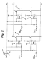
- Fig. 2 the drive of two of the three shown in Fig. 1 is shown Half bridges 14 shown. It is easy to see that the Control of the semiconductor switch via optocoupler 22 takes place, the control side with a common supply voltage, in the present case 5 volts and with the microcontroller 16 of the Inverter 5 are connected. In the supply line of the 5 volt power supply for the control electronics, the contact 23 of Safety relay 21 connected. By opening this contact 23 is the complete power supply of the control electronics for all six frequency converter semiconductor switches 12 simultaneously off. About a not shown, forcibly guided Contact is the switching state of the safety relay 21 to the higher-level control 2 reported. About another, too Forcibly guided contact can also be the microcontroller 16 of the Inverter 5 monitor the switching of the safety relay and at Malfunction prevent a restart. The function of the Switching element is checked and monitored after each trip.
- the current measuring device 15 is provided with current sensors for monitoring connected to the motor current. Occurs during standstill of the Drive in the event of an error on a current flow, it causes the controllable rectifier 7 is turned off.
- the current measuring device 15 is connected to the microcontroller 16 and this with the control electronics 8 for the thyristors T1 to T3 of the Bridge rectifier 7. About a potential-free contact is the higher-level elevator control 2 on the malfunction informed. About the higher-level control can then turn the safety relay 21 are controlled and the power supply the drive electronics of the frequency converter. 9 to be interrupted.
- the current measuring device 15 is for the controlled operation of Electric motor 4 is required and is also used for monitoring, as previously described, shared.
- the first switching module is through the controllable rectifier 7 and the second switching module by the frequency converter 9 and its semiconductor switch 12 formed.
- the function monitoring of the controllable rectifier 7 is performed by measuring the intermediate circuit voltage U ZK and the monitoring of the frequency converter 9 by measuring the motor currents.
Landscapes
- Control Of Ac Motors In General (AREA)
- Elevator Control (AREA)
- Control Of Electric Motors In General (AREA)
Description
Für den Betrieb eines Aufzugs oder dergleichen sind eine Aufzugssteuerung sowie ein Aufzugsantrieb vorgesehen. Die Aufzugssteuerung hat im wesentlichen die nachfolgenden Aufgaben:
- Ermittlung der aktuellen Position des Fahrkorbes im Schacht
- Auswertung der eingehenden Rufe (Kabinen- und Außenrufe)
- Entscheidung welche Position als nächstes angefahren wird
- Sicherheitsfunktionen:
- Überwachung der Kabinentüren
- Überwachung der Schachttüren
- Überwachung der Fahrkorbgeschwindigkeit
- Überwachung der Schutzräume
- Überwachung der Endschalter
- Überwachung der Fahrzeiten
Aus Sicherheitsgründen werden als Schaltelemente zwei voneinander unabhängige Schütze verwendet. Überwacht werden die Hauptschaltglieder dieser Schütze, wobei bei jedem Zwischenhalt, Richtungswechsel oder Stillsetzen des Aufzuges kontrolliert wird, ob die Hauptschaltglieder beider Schütze geöffnet sind und der Energiefluss unterbrochen ist. Ist dies nicht der Fall, wird durch die Überwachungseinrichtung ein erneutes Anfahren des Aufzuges verhindert. Zur Verhinderung eines ungewollten Anlaufs des Antriebsmotors erfolgt eine allpolige, elektromechanische Trennung des Antriebsmotors von seinem speisenden Netz. Die Trennung wird über Leistungsschütze vorgenommen. Diese elektromechanischen Schalter sind jedoch durch Kontaktabbrand verschleißbehaftet und können beim Kontaktieren auch verschweißen und dann nicht mehr geöffnet werden, weshalb beim Einsatz in Aufzugssteuerungen mit entsprechend höheren Sicherheitsanforderungen mindestens zwei in Reihe geschaltete Hauptschaltglieder eingesetzt werden müssen. Durch die in der Regel große Schalthäufigkeit und Belastung beim Einsatz in Aufzugsanlagen ist es erforderlich, die vergleichsweisen teuren Schütze von Zeit zu Zeit auszutauschen, wodurch entsprechend hohe Betriebskosten entstehen.
Bei Aufzugsanlagen mit einem an einem Wechselstromnetz betriebenen, drehzahlvariablen Aufzugsantrieb weist dieser einen an das Wechselstromnetz angeschlossenen Umrichter auf, der einen Gleichrichter sowie einen über einen Zwischenkreis angeschlossenen Wechselrichter beinhaltet. An den Wechselrichter ist ein Elektromotor angeschlossen.
Aus der EP-A-0 767 133 ist ein solcher drehzahlvariabler Aufzugsantrieb bekannt. Dieser weist eine Einrichtung zur Fehlererkennung auf. Dabei ist einer der beiden aus Sicherheitsgründen bisher verwendeten, voneinander unabhängigen, elektromechanischen Schalter ersetzt, indem im Störungsfall ein den Wechselrichter steuerndes, pulsweitenmoduliertes Steuersignal unterbunden wird. Zum Erkennen eines Störungsfalls wird hinter dem Gleichrichter im Zwischenkreis der Eingangsstrom des Wechselrichters gemessen.
Damit kann zwar einer der elektromechanischen Schalter ersetzt werden, es ist aber immer noch ein zur Sicherheitsabschaltung gehörender, elektromechanischer Schalter erforderlich. Außerdem ist eine eindeutige Fehlerzuordnung problematisch, weil ein gemessener Stromfluss im Zwischenkreis auch durch defekte Halbleiterschalter des Wechselrichters verursacht werden kann.
Die bei bisherigen Aufzügen vorgesehenen Schütze mit ihren mechanischen Kontakten können dadurch entfallen, ohne dass Nachteile bezüglich der Sicherheit eintreten. Durch das verschleißfreie Ein- und Ausschalten des Motors ist vielmehr die Betriebssicherheit und Lebensdauer der Anlage insgesamt wesentlich erhöht und gleichzeitig sind Überwachungsmaßnahmen vorhanden, durch welche die bisherigen Sicherheitsanforderungen hinsichtlich der Betriebsüberwachung weiterhin zumindest erfüllt sind.
Dazu ist eines der in der Regel zwei bislang vorgesehenen Schütze durch die mit einer Ansteuerelektronik verbundenen Halbleiterschalter des Frequenzumrichters ersetzt, zu deren Überwachung die Motorstrommessvorrichtung vorgesehen ist.
Die Funktion des zweiten, sonst vorgesehenen Schützes übernimmt der steuerbare Gleichrichter, dessen Ansteuerung nach jeder Fahrt des Aufzuges abgeschaltet wird.
Es sind somit, vergleichbar mit den beiden elektromechanischen Schaltern bei bisherigen Aufzugssteuerungen, ebenfalls zwei voneinander unabhängige Schalter vorhanden, die aber durch elektronische Schalter oder elektronische Baugruppen gebildet sind.
Vorteilhafte Ausgestaltungen der Erfindung ergeben sich aus den abhängigen Ansprüchen.
Die Maßnahmen des Anspruches 2 bewirken, dass zur zusätzlichen Sicherheit im Störungsfall bei Überschreiten eines vorgebbaren Gleichspannungsschwellwertes außer dem Sperren der Halbleiterschalter des Frequenzumrichters eine Fehlermeldung an eine übergeordnete Steuerung vorgenommen werden kann, welche die Ansteuerversorgungsspannung der Halbleiterschalter unterbricht.
Die vorgesehenen Überwachungseinrichtungen dieser elektronischen Baugruppen genügen zumindest den gleichen Sicherheitsanforderungen wie bisher. Hinzu kommt, dass durch den Einsatz eines Wechsel- oder Frequenzumrichters ein geregelter Betrieb des Antriebsmotors über einen großen Betriebsbereich möglich ist.
- Fig. 1
- ein Blockschaltbild einer Aufzugselektrik mit einer Aufzugssteuerung, einem Umrichter, einem Versorgungsnetz sowie einem Elektromotor und
- Fig. 2
- einSchaltungsausschnittzweierzueinemFrequenzumrichter gehörender Halbbrücken.
Im Fehlerfall wird somit nicht nur über die Ansteuerung des Frequenzumrichters ein Durchschalten der Halbleiterschalter 12 verhindert, sondern es wird zur zusätzlichen Sicherheit auch die zur Ansteuerung notwendige Spannungsversorgung komplett abgeschaltet. Damit ist auch bei einer ungewollten Ansteuerung der Halbleiterschalter 12 sicher ein Anlaufen des Elektromotors 4 im Fehlerfall verhindert.
Claims (11)
- Verfahren zum Betreiben eines elektromotorischen Antriebs für einen Aufzug, eine Fahrtreppe oder dergleichen, wobei der Antrieb einen Elektromotor (4) aufweist, der über einen Umrichter (5) aus einem Wechselstromnetz (6) betrieben wird, wobei die Wechselspannung mit einem Gleichrichter gleichgerichtet und diese Zwischenkreis-Gleichspannung dem Elektromotor (4) über einen Frequenzumrichter (9) mit steuerbaren Halbleiterschaltern (12) zugeführt wird und wobei eine Überwachung des Betriebszustands vorgenommen wird und bei einem Fehler die Stromversorgung des elektromotorischen Antriebs wenigstens zweifach unterbrochen wird, wobei der Motorstrom gemessen wird und am Ende jedes Fahrabschnittes bei stehendem Motor überprüft wird, ob ein Motorstrom fließt und dass in diesem Betriebszustand im Fall eines Motorstromflusses das erneute Einschalten der Gleichspannung gesperrt und die Ansteuerung der Halbleiterschalter (12) des Frequenzumrichters (9) unterbrochen wird dadurch gekennzeichnet, dass die Wechselspannung mit einem steuerbaren Gleichrichter (7) gleichgerichtet wird und die Gleichspannung mit dem steuerbaren Gleichrichter (7) ein- und ausschaltbar ist.
- Verfahren nach Anspruch 1, dadurch gekennzeichnet, dass die Gleichspannung als kondensatorgepufferte Zwischenkreisspannung (UZK) dem Elektromotor (4) über den Frequenzumrichter (9) zugeführt wird, dass die Zwischenkreisspannung (UZK) bei abgeschalteter Gleichspannung überwacht und im Störungsfall bei Überschreiten eines vorgebbaren, gegenüber dem Fahrbetriebszustand abgesenkten Gleichspannungsschwellwertes der Zwischenkreisspannung (UZK) die Ansteuerung der Halbleiterschalter (12) des Frequenzumrichters (9) unterbrochen wird.
- Verfahren nach Anspruch 1 oder 2, dadurch gekennzeichnet, dass die Zwischenkreisspannung (UZK) vorzugsweise von einem Microcontroller (16) des Umrichters (5) überwacht und im Störungsfall bei Überschreiten eines vorgebbaren Gleichspannungsschwellwertes die Halbleiterschalter (12) des Frequenzumrichters (9) gesperrt werden und eine Fehlermeldung an eine übergeordnete Steuerung (2) vorgenommen wird, welche die Ansteuerversorgungsspannung der Halbleiterschalter (12) unterbricht.
- Verfahren nach einem der Ansprüche 1 bis 3, dadurch gekennzeichnet, dass die Motorströme von einem Microcontroller (16) des Umrichters (5) überwacht und im Störungsfall bei Stromfluss während einer Stillstandsphase das Einschalten der Gleichspannung gesperrt und eine Fehlermeldung an die übergeordnete Steuerung (2) geleitet wird.
- Aufzug oder Fahrtreppe mit einer Aufzugselektrik, die eine übergeordnete Steuerung und einen Antrieb umfasst, wobei der Antrieb wenigstens einen Elektromotor (4) beinhaltet, der über Schaltelemente mit einem Wechselstrom-Versorgungsnetz (6) verbindbar ist, wobei zwischen dem Wechselstrom-Versorgungsnetz (6) und dem Elektromotor (4) ein Umrichter (5) zwischengeschaltet ist, der einen an das Wechselstrom-Versorgungsnetz (6) angeschlossenen Gleichrichter (7) und einen Frequenzumrichter (9) mit steuerbaren Halbleiterschaltern (12) aufweist, und wobei eine mit der Steuerung verbundene Überwachungseinrichtung zur Unterbrechung des Energieflusses im Störungsfall vorgesehen ist, wobei eine Strommessvorrichtung (15) zur Messung des Motorstroms sowie ein Microcontroller (16) als Teil der Überwachungseinrichtung vorgesehen sind dadurch gekennzeichnet, dass als Gleichrichter ein steuerbarer und mittels einer Ansteuerelektronik (8) ein- und ausschaltbarer Gleichrichter (7) vorgesehen ist.
- Aufzug nach Anspruch 5, dadurch gekennzeichnet, dass eine Messeinrichtung (11) zur Überwachung der vom steuerbaren Gleichrichter (7) gelieferten, kondensatorgepufferten Gleichspannung vorgesehen ist.
- Aufzug nach Anspruch 5 oder 6, dadurch gekennzeichnet, dass der Microcontroller (16) vorzugsweise über eine Schnittstelle (17) mit der übergeordneten Steuerung (2) verbunden ist.
- Aufzug nach einem der Ansprüche 5 bis 7, dadurch gekennzeichnet, dass der steuerbaren Gleichrichter (7) durch eine halbgesteuerte Brückenschaltung gebildet ist, die bei Drehstromversorgung insbesondere drei Dioden (D1-D3) und drei Thyristoren (T1-T3) umfasst.
- Aufzug nach einem der Ansprüche 5 bis 8, dadurch gekennzeichnet, dass die steuerbaren Halbleiterschalter (12) des Frequenzumrichters (9) durch vorzugsweise drei Halbbrücken (14) bei Einsatz eines dreiphasigen Motors gebildet ist und dass als Halbleiterschalter (12) insbesondere IGBTs (Isolatet Gate Bipolar Transistors) vorgesehen sind.
- Aufzug nach einem der Ansprüche 5 bis 9, dadurch gekennzeichnet, dass zur Ansteuerung der Halbleiterschalter (12) des Frequenzumrichters (9) Optokoppler (22) vorgesehen sind, die ansteuerseitig mit einer gemeinsamen Versorgungsspannung sowie mit dem Microcontroller (16) des Umrichters (5) verbunden sind und dass in die Zuleitung dieser Versorgungsspannung ein zu einem von der übergeordneten Steuerung (2) ansteuerbares Sicherheitsrelais (21) gehörender Kontakt (23) eingesetzt ist.
- Aufzug nach Anspruch 10, dadurch gekennzeichnet, dass das Sicherheitsrelais (21) einen potentialfreien Kontakt zur Rückmeldung seiner Funktion an die übergeordnete Steuerung (2) und vorzugsweise einen weiteren potentialfreien Kontakt zur Rückmeldung seiner Funktion an den Microprozessor (16) aufweist.
Priority Applications (1)
| Application Number | Priority Date | Filing Date | Title |
|---|---|---|---|
| DE20023348U DE20023348U1 (de) | 1999-03-18 | 2000-03-11 | Aufzug oder Fahrtreppe |
Applications Claiming Priority (2)
| Application Number | Priority Date | Filing Date | Title |
|---|---|---|---|
| DE19912062A DE19912062A1 (de) | 1999-03-18 | 1999-03-18 | Verfahren zum Betreiben eines elektromotorischen Antriebs für einen Aufzug und danach betriebener Aufzug |
| DE19912062 | 1999-03-18 |
Publications (3)
| Publication Number | Publication Date |
|---|---|
| EP1037354A2 EP1037354A2 (de) | 2000-09-20 |
| EP1037354A3 EP1037354A3 (de) | 2001-08-08 |
| EP1037354B1 true EP1037354B1 (de) | 2004-01-02 |
Family
ID=7901410
Family Applications (1)
| Application Number | Title | Priority Date | Filing Date |
|---|---|---|---|
| EP00105193A Expired - Lifetime EP1037354B1 (de) | 1999-03-18 | 2000-03-11 | Verfahren zum Betreiben eines elektromotorischen Antriebs für einen Aufzug und danach betriebener Aufzug |
Country Status (4)
| Country | Link |
|---|---|
| EP (1) | EP1037354B1 (de) |
| AT (1) | ATE257288T1 (de) |
| DE (2) | DE19912062A1 (de) |
| ES (1) | ES2211398T3 (de) |
Families Citing this family (11)
| Publication number | Priority date | Publication date | Assignee | Title |
|---|---|---|---|---|
| FI112006B (fi) | 2001-11-14 | 2003-10-15 | Kone Corp | Sähkömoottorikäyttö |
| DE10261452B4 (de) * | 2002-12-31 | 2011-02-03 | Danfoss Drives A/S | Motorsteuerung mit einer Steuereinrichtung und einer Sicherheitsvorrichtung zum sicheren Abschalten eines Motors |
| DE10318521A1 (de) | 2003-04-24 | 2004-11-25 | Leopold Kostal Gmbh & Co Kg | Elektrische Schaltungsanordnung |
| ATE528848T1 (de) * | 2004-10-07 | 2011-10-15 | Sew Eurodrive Gmbh & Co | Motorsteuerung |
| JP2007137586A (ja) * | 2005-11-17 | 2007-06-07 | Shangyin Sci & Technol Co Ltd | ボールねじ式エレベータの制御構造 |
| DE102005059790A1 (de) * | 2005-12-14 | 2007-06-28 | Hiwin Technologies Corp. | Steuermechanismus für Aufzüge unter Verwendung einer Kugelumlaufspindel |
| DE102010038432A1 (de) * | 2010-07-26 | 2012-01-26 | Thyssenkrupp Aufzugswerke Gmbh | Aufzugsteuereinrichtung |
| WO2012141713A1 (en) | 2011-04-15 | 2012-10-18 | Otis Elevator Company | Elevator drive power supply control |
| JP2014531377A (ja) | 2011-10-06 | 2014-11-27 | オーチス エレベータ カンパニーOtis Elevator Company | エレベータブレーキ制御 |
| FI123506B (fi) | 2012-05-31 | 2013-06-14 | Kone Corp | Hissin käyttölaite sekä hissin turvajärjestely |
| EP4708664A3 (de) * | 2019-03-29 | 2026-05-20 | Inventio Ag | Sicherheitsdrehmomentabschalteinrichtung zum unterbrechen einer drehmomenterzeugung durch eine von einer leistungsversorgungseinrichtung versorgte antriebsmaschine einer aufzuganlage |
Family Cites Families (1)
| Publication number | Priority date | Publication date | Assignee | Title |
|---|---|---|---|---|
| DE69622655T2 (de) * | 1995-10-05 | 2003-04-03 | Otis Elevator Co., Farmington | Fehlerdetektor für Aufzugsantrieb |
-
1999
- 1999-03-18 DE DE19912062A patent/DE19912062A1/de not_active Withdrawn
-
2000
- 2000-03-11 AT AT00105193T patent/ATE257288T1/de not_active IP Right Cessation
- 2000-03-11 EP EP00105193A patent/EP1037354B1/de not_active Expired - Lifetime
- 2000-03-11 ES ES00105193T patent/ES2211398T3/es not_active Expired - Lifetime
- 2000-03-11 DE DE50004898T patent/DE50004898D1/de not_active Expired - Lifetime
Also Published As
| Publication number | Publication date |
|---|---|
| ATE257288T1 (de) | 2004-01-15 |
| DE19912062A1 (de) | 2000-09-28 |
| DE50004898D1 (de) | 2004-02-05 |
| EP1037354A2 (de) | 2000-09-20 |
| EP1037354A3 (de) | 2001-08-08 |
| ES2211398T3 (es) | 2004-07-16 |
Similar Documents
| Publication | Publication Date | Title |
|---|---|---|
| EP0903314B1 (de) | Ueberwachungseinrichtung für eine Antriebssteuerung für Aufzüge | |
| EP2493802B1 (de) | Sicherheitskreis in einer aufzugsanlage | |
| DE3882902T2 (de) | Wechselstrommotorregelungssystem mit notsteuerung. | |
| EP2227357B1 (de) | Industrieroboter mit einer redundanten notbremsschaltung | |
| EP3793925B1 (de) | Inspektionssteuerungssystem einer aufzugsanlage sowie verfahren zum umschalten einer aufzugsanlage zwischen einem normal- und einem inspektionsbetrieb | |
| DE102018107771B4 (de) | Umrichtergerät, das eine Funktion zum Erfassen eines Defekts eines Leistungsbauteiles hat, und Verfahren zum Erfassen eines Defekts eines Leistungsbauteils | |
| DE19754141C2 (de) | Sicherheitseinrichtung für Rolltreppen und Rollsteige | |
| EP1037354A2 (de) | Verfahren zum Betreiben eines elektromotorischen Antriebs für einen Aufzug und danach betriebener Aufzug | |
| DE102008058303B4 (de) | Verfahren zum Betreiben eines Antriebs und Antriebssystem | |
| CH663497A5 (de) | Antriebsanordnung mit einer schutzeinrichtung fuer die leistungstransistoren eines umformers. | |
| DE69622655T2 (de) | Fehlerdetektor für Aufzugsantrieb | |
| HK1039607A1 (en) | Method for disconnecting transport systems for persons and a security circuit for transport systems for persons | |
| EP4708664A2 (de) | Sicherheitsdrehmomentabschalteinrichtung zum unterbrechen einer drehmomenterzeugung durch eine von einer leistungsversorgungseinrichtung versorgte antriebsmaschine einer aufzuganlage | |
| EP3704048A1 (de) | Sicherheitsüberwachungsvorrichtung zum überwachen von sicherheitsrelevanten zuständen in einer personenförderanlage sowie verfahren zum betreiben derselben | |
| EP0149727B1 (de) | Überwachungsschaltung für die Sicherheitskontakte von Aufzügen | |
| DE68906970T2 (de) | Steuermittel fuer einen elektrischen universalmotor. | |
| WO2016037673A1 (de) | Förderanlage mit sicherheitsfunktion | |
| EP0644050A1 (de) | Steuereinrichtung für eine Druckmaschine | |
| EP1667302A2 (de) | Verfahren und Vorrichtung zur Erfassung eines fehlerhaften Stromes oder einer fehlerhaften Spannung und Abschaltung der Versorgungsspannung | |
| DE20023348U1 (de) | Aufzug oder Fahrtreppe | |
| EP1323661B1 (de) | Verfahren zum Anhalten einer Personenfördereinrichtung | |
| DE19606894A1 (de) | Einrichtung zur signaltechnisch sicheren Steuerung und Überwachung elektrischer Verbraucher im Eisenbahnwesen | |
| EP1088781B1 (de) | Überwachungseinrichtung für eine Antriebseinrichtung für Aufzüge | |
| CH691100A5 (de) | Verfahren zur Überwachung eines Drehstrommotors sowie Überwachungseinrichtung. | |
| EP4121383B1 (de) | Steuereinheit für eine aufzugsanlage |
Legal Events
| Date | Code | Title | Description |
|---|---|---|---|
| PUAI | Public reference made under article 153(3) epc to a published international application that has entered the european phase |
Free format text: ORIGINAL CODE: 0009012 |
|
| AK | Designated contracting states |
Kind code of ref document: A2 Designated state(s): AT BE CH CY DE DK ES FI FR GB GR IE IT LI LU MC NL PT SE |
|
| AX | Request for extension of the european patent |
Free format text: AL;LT;LV;MK;RO;SI |
|
| PUAL | Search report despatched |
Free format text: ORIGINAL CODE: 0009013 |
|
| AK | Designated contracting states |
Kind code of ref document: A3 Designated state(s): AT BE CH CY DE DK ES FI FR GB GR IE IT LI LU MC NL PT SE |
|
| AX | Request for extension of the european patent |
Free format text: AL;LT;LV;MK;RO;SI |
|
| 17P | Request for examination filed |
Effective date: 20010707 |
|
| AKX | Designation fees paid |
Free format text: AT BE CH CY DE DK ES FI FR GB GR IE IT LI LU MC NL PT SE |
|
| 17Q | First examination report despatched |
Effective date: 20030217 |
|
| GRAP | Despatch of communication of intention to grant a patent |
Free format text: ORIGINAL CODE: EPIDOSNIGR1 |
|
| RAP1 | Party data changed (applicant data changed or rights of an application transferred) |
Owner name: ZIEHL-ABEGG AG |
|
| GRAS | Grant fee paid |
Free format text: ORIGINAL CODE: EPIDOSNIGR3 |
|
| GRAA | (expected) grant |
Free format text: ORIGINAL CODE: 0009210 |
|
| AK | Designated contracting states |
Kind code of ref document: B1 Designated state(s): AT BE CH CY DE DK ES FI FR GB GR IE IT LI LU MC NL PT SE |
|
| PG25 | Lapsed in a contracting state [announced via postgrant information from national office to epo] |
Ref country code: NL Free format text: LAPSE BECAUSE OF FAILURE TO SUBMIT A TRANSLATION OF THE DESCRIPTION OR TO PAY THE FEE WITHIN THE PRESCRIBED TIME-LIMIT Effective date: 20040102 Ref country code: IE Free format text: LAPSE BECAUSE OF FAILURE TO SUBMIT A TRANSLATION OF THE DESCRIPTION OR TO PAY THE FEE WITHIN THE PRESCRIBED TIME-LIMIT Effective date: 20040102 Ref country code: FI Free format text: LAPSE BECAUSE OF FAILURE TO SUBMIT A TRANSLATION OF THE DESCRIPTION OR TO PAY THE FEE WITHIN THE PRESCRIBED TIME-LIMIT Effective date: 20040102 Ref country code: CY Free format text: LAPSE BECAUSE OF FAILURE TO SUBMIT A TRANSLATION OF THE DESCRIPTION OR TO PAY THE FEE WITHIN THE PRESCRIBED TIME-LIMIT Effective date: 20040102 |
|
| REG | Reference to a national code |
Ref country code: GB Ref legal event code: FG4D Free format text: NOT ENGLISH |
|
| REG | Reference to a national code |
Ref country code: CH Ref legal event code: EP |
|
| REG | Reference to a national code |
Ref country code: IE Ref legal event code: FG4D Free format text: GERMAN |
|
| REF | Corresponds to: |
Ref document number: 50004898 Country of ref document: DE Date of ref document: 20040205 Kind code of ref document: P |
|
| REG | Reference to a national code |
Ref country code: CH Ref legal event code: NV Representative=s name: HANS RUDOLF GACHNANG PATENTANWALT |
|
| PG25 | Lapsed in a contracting state [announced via postgrant information from national office to epo] |
Ref country code: AT Free format text: LAPSE BECAUSE OF NON-PAYMENT OF DUE FEES Effective date: 20040311 Ref country code: LU Free format text: LAPSE BECAUSE OF NON-PAYMENT OF DUE FEES Effective date: 20040311 |
|
| PG25 | Lapsed in a contracting state [announced via postgrant information from national office to epo] |
Ref country code: BE Free format text: LAPSE BECAUSE OF NON-PAYMENT OF DUE FEES Effective date: 20040331 Ref country code: MC Free format text: LAPSE BECAUSE OF NON-PAYMENT OF DUE FEES Effective date: 20040331 |
|
| PG25 | Lapsed in a contracting state [announced via postgrant information from national office to epo] |
Ref country code: GR Free format text: LAPSE BECAUSE OF FAILURE TO SUBMIT A TRANSLATION OF THE DESCRIPTION OR TO PAY THE FEE WITHIN THE PRESCRIBED TIME-LIMIT Effective date: 20040402 Ref country code: SE Free format text: LAPSE BECAUSE OF FAILURE TO SUBMIT A TRANSLATION OF THE DESCRIPTION OR TO PAY THE FEE WITHIN THE PRESCRIBED TIME-LIMIT Effective date: 20040402 Ref country code: DK Free format text: LAPSE BECAUSE OF FAILURE TO SUBMIT A TRANSLATION OF THE DESCRIPTION OR TO PAY THE FEE WITHIN THE PRESCRIBED TIME-LIMIT Effective date: 20040402 |
|
| NLV1 | Nl: lapsed or annulled due to failure to fulfill the requirements of art. 29p and 29m of the patents act | ||
| GBT | Gb: translation of ep patent filed (gb section 77(6)(a)/1977) |
Effective date: 20040512 |
|
| REG | Reference to a national code |
Ref country code: ES Ref legal event code: FG2A Ref document number: 2211398 Country of ref document: ES Kind code of ref document: T3 |
|
| REG | Reference to a national code |
Ref country code: IE Ref legal event code: FD4D |
|
| BERE | Be: lapsed |
Owner name: ZIEHL-ABEGG A.G. Effective date: 20040331 |
|
| ET | Fr: translation filed | ||
| PLBE | No opposition filed within time limit |
Free format text: ORIGINAL CODE: 0009261 |
|
| STAA | Information on the status of an ep patent application or granted ep patent |
Free format text: STATUS: NO OPPOSITION FILED WITHIN TIME LIMIT |
|
| 26N | No opposition filed |
Effective date: 20041005 |
|
| PG25 | Lapsed in a contracting state [announced via postgrant information from national office to epo] |
Ref country code: PT Free format text: LAPSE BECAUSE OF NON-PAYMENT OF DUE FEES Effective date: 20040602 |
|
| REG | Reference to a national code |
Ref country code: CH Ref legal event code: NV Representative=s name: GACHNANG AG PATENTANWAELTE, CH |
|
| REG | Reference to a national code |
Ref country code: FR Ref legal event code: PLFP Year of fee payment: 16 |
|
| PGFP | Annual fee paid to national office [announced via postgrant information from national office to epo] |
Ref country code: ES Payment date: 20150210 Year of fee payment: 16 Ref country code: CH Payment date: 20150320 Year of fee payment: 16 |
|
| PGFP | Annual fee paid to national office [announced via postgrant information from national office to epo] |
Ref country code: GB Payment date: 20150317 Year of fee payment: 16 Ref country code: FR Payment date: 20150217 Year of fee payment: 16 |
|
| PGFP | Annual fee paid to national office [announced via postgrant information from national office to epo] |
Ref country code: IT Payment date: 20150330 Year of fee payment: 16 |
|
| REG | Reference to a national code |
Ref country code: CH Ref legal event code: PL |
|
| GBPC | Gb: european patent ceased through non-payment of renewal fee |
Effective date: 20160311 |
|
| REG | Reference to a national code |
Ref country code: FR Ref legal event code: ST Effective date: 20161130 |
|
| PG25 | Lapsed in a contracting state [announced via postgrant information from national office to epo] |
Ref country code: LI Free format text: LAPSE BECAUSE OF NON-PAYMENT OF DUE FEES Effective date: 20160331 Ref country code: CH Free format text: LAPSE BECAUSE OF NON-PAYMENT OF DUE FEES Effective date: 20160331 Ref country code: GB Free format text: LAPSE BECAUSE OF NON-PAYMENT OF DUE FEES Effective date: 20160311 Ref country code: FR Free format text: LAPSE BECAUSE OF NON-PAYMENT OF DUE FEES Effective date: 20160331 |
|
| PG25 | Lapsed in a contracting state [announced via postgrant information from national office to epo] |
Ref country code: IT Free format text: LAPSE BECAUSE OF NON-PAYMENT OF DUE FEES Effective date: 20160311 |
|
| REG | Reference to a national code |
Ref country code: ES Ref legal event code: FD2A Effective date: 20170427 |
|
| PG25 | Lapsed in a contracting state [announced via postgrant information from national office to epo] |
Ref country code: ES Free format text: LAPSE BECAUSE OF NON-PAYMENT OF DUE FEES Effective date: 20160312 |
|
| PGFP | Annual fee paid to national office [announced via postgrant information from national office to epo] |
Ref country code: DE Payment date: 20180410 Year of fee payment: 19 |
|
| REG | Reference to a national code |
Ref country code: DE Ref legal event code: R119 Ref document number: 50004898 Country of ref document: DE |
|
| PG25 | Lapsed in a contracting state [announced via postgrant information from national office to epo] |
Ref country code: DE Free format text: LAPSE BECAUSE OF NON-PAYMENT OF DUE FEES Effective date: 20191001 |