EP1037347A1 - Schnellbefestigung zum Aufschnappen eines elektrischen Installationsgerätes auf eine Hutprofiltragschiene - Google Patents
Schnellbefestigung zum Aufschnappen eines elektrischen Installationsgerätes auf eine Hutprofiltragschiene Download PDFInfo
- Publication number
- EP1037347A1 EP1037347A1 EP00104870A EP00104870A EP1037347A1 EP 1037347 A1 EP1037347 A1 EP 1037347A1 EP 00104870 A EP00104870 A EP 00104870A EP 00104870 A EP00104870 A EP 00104870A EP 1037347 A1 EP1037347 A1 EP 1037347A1
- Authority
- EP
- European Patent Office
- Prior art keywords
- slide
- arms
- rail
- hat
- fastening according
- Prior art date
- Legal status (The legal status is an assumption and is not a legal conclusion. Google has not performed a legal analysis and makes no representation as to the accuracy of the status listed.)
- Granted
Links
Images

Classifications
-
- H—ELECTRICITY
- H02—GENERATION; CONVERSION OR DISTRIBUTION OF ELECTRIC POWER
- H02B—BOARDS, SUBSTATIONS OR SWITCHING ARRANGEMENTS FOR THE SUPPLY OR DISTRIBUTION OF ELECTRIC POWER
- H02B1/00—Frameworks, boards, panels, desks, casings; Details of substations or switching arrangements
- H02B1/015—Boards, panels, desks; Parts thereof or accessories therefor
- H02B1/04—Mounting thereon of switches or of other devices in general, the switch or device having, or being without, casing
- H02B1/052—Mounting on rails
-
- H—ELECTRICITY
- H02—GENERATION; CONVERSION OR DISTRIBUTION OF ELECTRIC POWER
- H02B—BOARDS, SUBSTATIONS OR SWITCHING ARRANGEMENTS FOR THE SUPPLY OR DISTRIBUTION OF ELECTRIC POWER
- H02B1/00—Frameworks, boards, panels, desks, casings; Details of substations or switching arrangements
- H02B1/015—Boards, panels, desks; Parts thereof or accessories therefor
- H02B1/04—Mounting thereon of switches or of other devices in general, the switch or device having, or being without, casing
- H02B1/052—Mounting on rails
- H02B1/0523—Mounting on rails locked into position by a sliding member
Definitions
- the invention relates to a quick attachment for snapping an electrical Installation device on a top-hat rail according to the preamble of the claim 1.
- Such quick attachments are on the bottom side of an electrical installation device provided, the installation device on its mounting surface a U-shaped Has recess, on one side wall a fixed nose and on the other side wall a nose arranged on a slide is provided are facing each other, the slide against the pressure of a Spring is pressed inwards and so the so-called movable nose formed on it pushes inwards into the recess.
- a U-shaped Has recess on one side wall a fixed nose and on the other side wall a nose arranged on a slide is provided are facing each other, the slide against the pressure of a Spring is pressed inwards and so the so-called movable nose formed on it pushes inwards into the recess.
- a slide In a line circuit breaker, such a slide is known as a metal part is formed and pressed under the pressure of a helical compression spring becomes. To disassemble the slide against the pressure of the spring from the edge the top-hat rail is removed so that the installation device from the top-hat rail can be removed.
- a slide which has two parallel longitudinal webs between the nose and the opposite, to attack a tool has suitable end, on the inner longitudinal edges of which arms are formed, which each protrude beyond the other longitudinal web and engage in recesses on the housing.
- the arms thus serve as springs that slide the slide against the top-hat rail to press.
- the longitudinal webs also deform, which lead to jamming of the slide in the housing of the installation device can.
- the longitudinal webs are arranged in different levels, whereby the slide is to be manufactured with complicated tools and is unstable.
- the object of the invention is to a quick attachment of the type mentioned create, in which the effort to manufacture and assembly are simplified, at optimal functioning.
- the slide should be an elongated Point the slide body parallel to its direction of movement running side edges projecting in opposite directions resilient Arms are formed which engage in recesses in the housing of the installation device and support it and so the slider resiliently against the top-hat rail to press;
- a retaining lug is attached to the slide, which prevents a return on the installation device to limit the inward movement in the unmounted Condition serves.
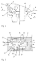
- a circuit breaker 10 has a front side 11, from which a switch toggle 12 protrudes.
- the mounting surface 13 On the opposite side is the mounting surface 13, which has a U-shaped groove 14, on one side wall a fixed nose 15 and on the other side wall a movable nose 16 is arranged.
- This movable nose 16 is pressed resiliently into the interior of the recess, so that if the circuit breaker is placed on a hat profile mounting rail 21 shown in broken lines is snapped on, both the fixed nose 15 and the movable nose 16th reach behind the adjacent longitudinal edges of the hat rail 21.
- the movable nose 16 is formed on a slide 17, which on the nose 16 opposite end has a fold 18 away from the fastening surface 13, behind which a tool 19 can reach by being supported against a wall 20 pull the slider in the direction of arrow P away from the top-hat rail, see above that the movable nose 16 is released from the hat rail 21.
- the slide 17 has an elongated slide body 17a made of plastic, which between a lower housing part 22 and an upper housing part 23, which by a parting line 24 are separated from one another, is arranged. Owns for this purpose the housing not shown housing recesses, which the slide in Lead arrow direction P.
- the arms 27 and 28 each engage laterally in a recess 31 and 32, wherein the recess 31 has a shoulder 33 on its wall remote from the nose and an adjoining inclined surface 34; has the recess 32 a further inclined surface 35 corresponding to the inclined surface 34.
- the paragraph 33 and the inclined surfaces 34 and 35 are dimensioned to the slide, that the arms 27 and 28 lie precisely against the shoulder 33 or on the inclined surface 35, when the nose is pressed inside the recess, so that in this position the resilient arms 27 and 28 are approximately relaxed.
- the Nose 15 placed behind the adjacent edge of the hat profile mounting rail 21.
- the other Edge of the hat profile mounting rail 21 slides on the inclined surface 16a of the nose 16 and locked behind an undercut 16b of the nose 16, thereby the slider is slightly pushed to the left in the direction of arrow P and the resilient Arms 28 and 27 are pressed against the inclined surface 35 or against the shoulder 33.
- the slide is moved further in the direction of arrow P by means of tool 19 moved, the resilient arms are bent further and the nose 16 of the adjacent edge of the hat rail 21 is released.
- the circuit breaker according to the drawings has on its mounting surface two vertically projecting connecting lugs 36 and 37, which in the assembled state engage mating contact pieces in a distribution plate; these connecting flags are known per se, for example from DE 196 28 957.2 A1.
- a nose 40 is provided in the region of the nose, which is designed like a saw tooth and in the position shown in Fig. 2, that is in the not mounted on the mounting rail 21 State, is pressed against a recess 41 by the resilient arms with slight force, so that the slide 17 does not slide freely into the interior of the recess 14 can.
Landscapes
- Engineering & Computer Science (AREA)
- Power Engineering (AREA)
- Breakers (AREA)
- Connections Arranged To Contact A Plurality Of Conductors (AREA)
- Insulating Bodies (AREA)
- Details Of Indoor Wiring (AREA)
- Mounting Components In General For Electric Apparatus (AREA)
Abstract
Description
- Fig. 1
- eine Seitenansicht eines Leitungsschutzschalters,
- Fig. 2
- einen Teilbereich des Leitungsschutzschalters gemäß Fig. 1, bei geöffnetem Gehäuse, und
- Fig. 3
- eine Schnittansicht gemäß Schnittlinie III-III der Fig. 2.
Claims (7)
- Schnellbefestigung zum Aufschnappen eines elektrischen Installationsgerätes, insbesondere eines Leitungsschutzschalters auf eine Hutprofiltragschiene, mit einer Ausnehmung (14) an der Befestigungsfläche des elektrischen Installationsgerätes (10) und mit einem federnd in die Ausnehmung (14) gedrückten, aus Kunststoff bestehenden Schieber (17), der in aufgerastetem Zustand mit einer Nase (16) hinter eine Längskante der Hutprofiltragschiene greift, dadurch gekennzeichnet, daß der Schieber (17) einen langgestreckten Schieberkörper aufweist, an dessen parallel zur Bewegungsrichtung verlaufenden Seitenkanten (25, 26) in entgegengesetzte Richtungen und parallel zur Längserstreckung der Hutprofiltragschiene (14) vorstehende federnde Arme (27, 28) angeformt sind, die in Gehäuseausnehmungen (31, 32) eingreifen und sich darin abstützen und so den Schieber (17) gegen die Hutprofiltragschiene (21) drücken, und daß am Schieber (17) eine Haltenase (40) angeformt ist, die gegen einen Rücksprung (41) am Installationsgerät zur Begrenzung der Bewegung nach innen im nicht montierten Zustand dient.
- Schnellbefestigung nach Anspruch 1, dadurch gekennzeichnet, daß am Schieber (17) beidseitig zu den Armen (27, 28) in den Schieberkörper eingreifende Vertiefungen (29, 30) vorgesehen sind, die die federnde Armlänge vergrößern.
- Schnellbefestigung nach Anspruch 1 oder 2, dadurch gekennzeichnet, daß die Arme (27, 28) fluchten.
- Schnellbefestigung nach einem der Ansprüche 1 bis 2, dadurch gekennzeichnet, daß die Arme (27, 28) gegeneinander versetzt sind und einen unterschiedlichen Abstand zur Hutprofiltragschiene (21) aufweisen.
- Schnellbefestigung nach Anspruch 4, dadurch gekennzeichnet, daß die Vertiefungen (29, 30) an der Längssymmetrieachse des Schieberkörpers enden.
- Schnellbefestigung nach einem der vorherigen Ansprüche, dadurch gekennzeichnet, daß die Gehäuseausnehmung (31, 32) Schrägflächen (34, 35) aufweisen, auf die die freien Enden der Arme (27, 28) beim Zurückziehen des Schiebers (17) von der Hutprofiltragschiene weg auflaufen.
- Schnellbefestigung nach Anspruch 6, dadurch gekennzeichnet, daß wenigstens eine der Schrägflächen (34) einen Absatz (33) aufweist, der senkrecht zur Bewegungsrichtung des Schiebers (17) ausgerichtet ist und gegen den der benachbarte Arm (27) dann anliegt, wenn der Schieber frei nach innen gedrückt wird und damit die Arme (27, 28) spannungsfrei sind.
Applications Claiming Priority (2)
| Application Number | Priority Date | Filing Date | Title |
|---|---|---|---|
| DE19912125A DE19912125B4 (de) | 1999-03-18 | 1999-03-18 | Schnellbefestigung zum Aufschnappen eines elektrischen Installationsgerätes auf eine Hutprofiltragschiene |
| DE19912125 | 1999-03-18 |
Publications (2)
| Publication Number | Publication Date |
|---|---|
| EP1037347A1 true EP1037347A1 (de) | 2000-09-20 |
| EP1037347B1 EP1037347B1 (de) | 2010-05-12 |
Family
ID=7901451
Family Applications (1)
| Application Number | Title | Priority Date | Filing Date |
|---|---|---|---|
| EP00104870A Expired - Lifetime EP1037347B1 (de) | 1999-03-18 | 2000-03-07 | Schnellbefestigung zum Aufschnappen eines elektrischen Installationsgerätes auf eine Hutprofiltragschiene |
Country Status (4)
| Country | Link |
|---|---|
| EP (1) | EP1037347B1 (de) |
| AT (1) | ATE467931T1 (de) |
| DE (2) | DE19912125B4 (de) |
| SG (1) | SG108220A1 (de) |
Cited By (1)
| Publication number | Priority date | Publication date | Assignee | Title |
|---|---|---|---|---|
| US7758368B2 (en) | 2007-05-29 | 2010-07-20 | Honeywell International Inc. | DIN rail mount |
Families Citing this family (2)
| Publication number | Priority date | Publication date | Assignee | Title |
|---|---|---|---|---|
| DE102013212335A1 (de) | 2012-08-31 | 2014-03-06 | Siemens Aktiengesellschaft | Schieber für ein modulares Reiheneinbaugerät, modulares Rei-heneinbaugerät sowie Sammelschienenverbund |
| DE102013112099B4 (de) | 2013-11-04 | 2021-10-07 | Phoenix Contact Gmbh & Co. Kg | Komponentenaufbausystem |
Citations (2)
| Publication number | Priority date | Publication date | Assignee | Title |
|---|---|---|---|---|
| DE19548335C1 (de) * | 1995-12-23 | 1996-12-12 | Bopla Gehaeuse Systeme Gmbh | Gehäuse zum Ansetzen an eine Tragschiene |
| US5598322A (en) * | 1994-09-27 | 1997-01-28 | Watlow Winona, Inc. | Power control system |
Family Cites Families (4)
| Publication number | Priority date | Publication date | Assignee | Title |
|---|---|---|---|---|
| GB1546566A (en) * | 1975-07-17 | 1979-05-23 | Arrow Hart Europe Ltd | Base for electrical components |
| DE3002589A1 (de) * | 1980-01-25 | 1981-08-06 | Schupa Elektro-GmbH + Co KG, 5885 Schalksmühle | Befestigung eines elektrischen schaltgeraetes auf einer als profilschiene ausgebildeten trageschiene |
| DE8800369U1 (de) * | 1988-01-14 | 1988-02-25 | Siemens AG, 1000 Berlin und 8000 München | Gehäuse mit einer Anordnung zum Befestigen an einer Tragschiene |
| DE19628957A1 (de) * | 1996-07-18 | 1998-01-22 | Abb Patent Gmbh | Anschlußvorrichtung für elektrische Installationsgeräte |
-
1999
- 1999-03-18 DE DE19912125A patent/DE19912125B4/de not_active Expired - Fee Related
-
2000
- 2000-03-02 SG SG200001162A patent/SG108220A1/en unknown
- 2000-03-07 EP EP00104870A patent/EP1037347B1/de not_active Expired - Lifetime
- 2000-03-07 AT AT00104870T patent/ATE467931T1/de active
- 2000-03-07 DE DE50015920T patent/DE50015920D1/de not_active Expired - Lifetime
Patent Citations (2)
| Publication number | Priority date | Publication date | Assignee | Title |
|---|---|---|---|---|
| US5598322A (en) * | 1994-09-27 | 1997-01-28 | Watlow Winona, Inc. | Power control system |
| DE19548335C1 (de) * | 1995-12-23 | 1996-12-12 | Bopla Gehaeuse Systeme Gmbh | Gehäuse zum Ansetzen an eine Tragschiene |
Cited By (1)
| Publication number | Priority date | Publication date | Assignee | Title |
|---|---|---|---|---|
| US7758368B2 (en) | 2007-05-29 | 2010-07-20 | Honeywell International Inc. | DIN rail mount |
Also Published As
| Publication number | Publication date |
|---|---|
| DE19912125A1 (de) | 2000-09-21 |
| EP1037347B1 (de) | 2010-05-12 |
| DE50015920D1 (de) | 2010-06-24 |
| ATE467931T1 (de) | 2010-05-15 |
| SG108220A1 (en) | 2005-01-28 |
| DE19912125B4 (de) | 2008-01-10 |
Similar Documents
| Publication | Publication Date | Title |
|---|---|---|
| EP3080875B2 (de) | Halterahmen für einen steckverbinder | |
| EP3843221B1 (de) | Halterahmen für einen steckverbinder | |
| EP4413292B1 (de) | Leuchte mit schutzabdeckung | |
| DE3149310A1 (de) | Vorrichtung und verfahren zur befestigung von elektrischen installationsgeraeten auf normprofilschienen, insbesondere auf hutprofilschienen | |
| DE10100460A1 (de) | Leistungshalbleitermodul mit Gehäuse und Anschlußelementen | |
| EP0984537B1 (de) | Schnellbefestigungsvorrichtung für ein elektrisches Installationsgerät zum Aufschnappen auf eine Hutprofiltragschiene | |
| EP1037347A1 (de) | Schnellbefestigung zum Aufschnappen eines elektrischen Installationsgerätes auf eine Hutprofiltragschiene | |
| EP0069045A2 (de) | Stecksockel für mehrpolige Niederspannungs-Schutzschalter | |
| DE19838432C1 (de) | Installationsgerät zur Montage an einer Hutschiene | |
| CH652269A5 (en) | Quick mounting base made of plastic, for fixing an electrical device or printed-circuit board | |
| DE4011447A9 (de) | Schnellbefestigung für ein elektrisches Installationsgerät | |
| EP0451726A1 (de) | Schnellbefestigung für ein elektrisches Installationsgerät | |
| DE202004008294U1 (de) | Montageadapter zum Aufrasten auf eine Tragschiene | |
| EP1149400A1 (de) | Elektrisches gerät mit einer verbindungseinrichtung zur verbindung mit einem zweiten elektrischen gerät | |
| CH657938A5 (de) | Schalter mit einem mit einer befestigungsvorrichtung versehenen gehaeuse. | |
| EP1038109B1 (de) | Elektrisches gerät mit einem verbindungsclip und einer verbindungsclipaufnahme zur verbindung mit einem zweiten elektrischen gerät | |
| WO2022008055A1 (de) | Schnapphaken | |
| DE10340209B4 (de) | Elektrisches Gerät mit Halte/-Lösevorrichtung | |
| EP1178582B1 (de) | Installationsgerät mit Riegel zur Montage an einer Hutschiene | |
| CH651158A5 (en) | Electrical switching apparatus which can be snapped onto a DIN standard top-hat profiled supporting rail | |
| EP0180206A2 (de) | Paketierte Sammelschiene | |
| DE10160543B4 (de) | Stromwandler für eine NH-Sicherungsleiste, NH-Sicherungs-Lastschalteinrichtung oder dergleichen | |
| EP1861859B1 (de) | Metallbügel zum halten von sicherungen im deckel eines sicherungslasttrennschalters | |
| DE2511422B2 (de) | Elektrischer Installationsschalter | |
| DE102023112178A1 (de) | Abgedichtetes Lichtband |
Legal Events
| Date | Code | Title | Description |
|---|---|---|---|
| PUAI | Public reference made under article 153(3) epc to a published international application that has entered the european phase |
Free format text: ORIGINAL CODE: 0009012 |
|
| AK | Designated contracting states |
Kind code of ref document: A1 Designated state(s): AT BE CH CY DE DK ES FI FR GB GR IE IT LI LU MC NL PT SE |
|
| AX | Request for extension of the european patent |
Free format text: AL;LT;LV;MK;RO;SI PAYMENT 20000315 |
|
| 17P | Request for examination filed |
Effective date: 20001017 |
|
| AKX | Designation fees paid |
Free format text: AT BE CH CY DE DK ES FI FR GB GR IE IT LI LU MC NL PT SE |
|
| AXX | Extension fees paid |
Free format text: SI PAYMENT 20000315 |
|
| RAP1 | Party data changed (applicant data changed or rights of an application transferred) |
Owner name: ABB PATENT GMBH |
|
| 17Q | First examination report despatched |
Effective date: 20070507 |
|
| GRAP | Despatch of communication of intention to grant a patent |
Free format text: ORIGINAL CODE: EPIDOSNIGR1 |
|
| GRAS | Grant fee paid |
Free format text: ORIGINAL CODE: EPIDOSNIGR3 |
|
| GRAA | (expected) grant |
Free format text: ORIGINAL CODE: 0009210 |
|
| RAP1 | Party data changed (applicant data changed or rights of an application transferred) |
Owner name: ABB AG |
|
| AK | Designated contracting states |
Kind code of ref document: B1 Designated state(s): AT BE CH CY DE DK ES FI FR GB GR IE IT LI LU MC NL PT SE |
|
| AX | Request for extension of the european patent |
Extension state: SI |
|
| REG | Reference to a national code |
Ref country code: GB Ref legal event code: FG4D Free format text: NOT ENGLISH |
|
| REG | Reference to a national code |
Ref country code: CH Ref legal event code: EP |
|
| REG | Reference to a national code |
Ref country code: IE Ref legal event code: FG4D Free format text: LANGUAGE OF EP DOCUMENT: GERMAN |
|
| REF | Corresponds to: |
Ref document number: 50015920 Country of ref document: DE Date of ref document: 20100624 Kind code of ref document: P |
|
| REG | Reference to a national code |
Ref country code: NL Ref legal event code: T3 |
|
| PG25 | Lapsed in a contracting state [announced via postgrant information from national office to epo] |
Ref country code: ES Free format text: LAPSE BECAUSE OF FAILURE TO SUBMIT A TRANSLATION OF THE DESCRIPTION OR TO PAY THE FEE WITHIN THE PRESCRIBED TIME-LIMIT Effective date: 20100823 Ref country code: SE Free format text: LAPSE BECAUSE OF FAILURE TO SUBMIT A TRANSLATION OF THE DESCRIPTION OR TO PAY THE FEE WITHIN THE PRESCRIBED TIME-LIMIT Effective date: 20100512 |
|
| PG25 | Lapsed in a contracting state [announced via postgrant information from national office to epo] |
Ref country code: FI Free format text: LAPSE BECAUSE OF FAILURE TO SUBMIT A TRANSLATION OF THE DESCRIPTION OR TO PAY THE FEE WITHIN THE PRESCRIBED TIME-LIMIT Effective date: 20100512 |
|
| REG | Reference to a national code |
Ref country code: IE Ref legal event code: FD4D |
|
| PG25 | Lapsed in a contracting state [announced via postgrant information from national office to epo] |
Ref country code: GR Free format text: LAPSE BECAUSE OF FAILURE TO SUBMIT A TRANSLATION OF THE DESCRIPTION OR TO PAY THE FEE WITHIN THE PRESCRIBED TIME-LIMIT Effective date: 20100813 Ref country code: CY Free format text: LAPSE BECAUSE OF NON-PAYMENT OF DUE FEES Effective date: 20100512 |
|
| PG25 | Lapsed in a contracting state [announced via postgrant information from national office to epo] |
Ref country code: DK Free format text: LAPSE BECAUSE OF FAILURE TO SUBMIT A TRANSLATION OF THE DESCRIPTION OR TO PAY THE FEE WITHIN THE PRESCRIBED TIME-LIMIT Effective date: 20100512 Ref country code: IE Free format text: LAPSE BECAUSE OF FAILURE TO SUBMIT A TRANSLATION OF THE DESCRIPTION OR TO PAY THE FEE WITHIN THE PRESCRIBED TIME-LIMIT Effective date: 20100512 Ref country code: PT Free format text: LAPSE BECAUSE OF FAILURE TO SUBMIT A TRANSLATION OF THE DESCRIPTION OR TO PAY THE FEE WITHIN THE PRESCRIBED TIME-LIMIT Effective date: 20100913 |
|
| PLBE | No opposition filed within time limit |
Free format text: ORIGINAL CODE: 0009261 |
|
| STAA | Information on the status of an ep patent application or granted ep patent |
Free format text: STATUS: NO OPPOSITION FILED WITHIN TIME LIMIT |
|
| 26N | No opposition filed |
Effective date: 20110215 |
|
| REG | Reference to a national code |
Ref country code: DE Ref legal event code: R097 Ref document number: 50015920 Country of ref document: DE Effective date: 20110214 |
|
| BERE | Be: lapsed |
Owner name: ABB A.G. Effective date: 20110331 |
|
| PG25 | Lapsed in a contracting state [announced via postgrant information from national office to epo] |
Ref country code: MC Free format text: LAPSE BECAUSE OF NON-PAYMENT OF DUE FEES Effective date: 20110331 |
|
| REG | Reference to a national code |
Ref country code: CH Ref legal event code: PL |
|
| PG25 | Lapsed in a contracting state [announced via postgrant information from national office to epo] |
Ref country code: BE Free format text: LAPSE BECAUSE OF NON-PAYMENT OF DUE FEES Effective date: 20110331 |
|
| PG25 | Lapsed in a contracting state [announced via postgrant information from national office to epo] |
Ref country code: LI Free format text: LAPSE BECAUSE OF NON-PAYMENT OF DUE FEES Effective date: 20110331 Ref country code: CH Free format text: LAPSE BECAUSE OF NON-PAYMENT OF DUE FEES Effective date: 20110331 |
|
| PGFP | Annual fee paid to national office [announced via postgrant information from national office to epo] |
Ref country code: FR Payment date: 20120403 Year of fee payment: 13 |
|
| PGFP | Annual fee paid to national office [announced via postgrant information from national office to epo] |
Ref country code: GB Payment date: 20120322 Year of fee payment: 13 |
|
| PGFP | Annual fee paid to national office [announced via postgrant information from national office to epo] |
Ref country code: IT Payment date: 20120330 Year of fee payment: 13 |
|
| REG | Reference to a national code |
Ref country code: AT Ref legal event code: MM01 Ref document number: 467931 Country of ref document: AT Kind code of ref document: T Effective date: 20110307 |
|
| PG25 | Lapsed in a contracting state [announced via postgrant information from national office to epo] |
Ref country code: AT Free format text: LAPSE BECAUSE OF NON-PAYMENT OF DUE FEES Effective date: 20110307 |
|
| PG25 | Lapsed in a contracting state [announced via postgrant information from national office to epo] |
Ref country code: LU Free format text: LAPSE BECAUSE OF NON-PAYMENT OF DUE FEES Effective date: 20110307 |
|
| GBPC | Gb: european patent ceased through non-payment of renewal fee |
Effective date: 20130307 |
|
| REG | Reference to a national code |
Ref country code: FR Ref legal event code: ST Effective date: 20131129 |
|
| PG25 | Lapsed in a contracting state [announced via postgrant information from national office to epo] |
Ref country code: GB Free format text: LAPSE BECAUSE OF NON-PAYMENT OF DUE FEES Effective date: 20130307 Ref country code: FR Free format text: LAPSE BECAUSE OF NON-PAYMENT OF DUE FEES Effective date: 20130402 |
|
| PG25 | Lapsed in a contracting state [announced via postgrant information from national office to epo] |
Ref country code: IT Free format text: LAPSE BECAUSE OF NON-PAYMENT OF DUE FEES Effective date: 20130307 |
|
| PGFP | Annual fee paid to national office [announced via postgrant information from national office to epo] |
Ref country code: DE Payment date: 20150320 Year of fee payment: 16 |
|
| REG | Reference to a national code |
Ref country code: DE Ref legal event code: R119 Ref document number: 50015920 Country of ref document: DE |
|
| PG25 | Lapsed in a contracting state [announced via postgrant information from national office to epo] |
Ref country code: DE Free format text: LAPSE BECAUSE OF NON-PAYMENT OF DUE FEES Effective date: 20161001 |
|
| PGFP | Annual fee paid to national office [announced via postgrant information from national office to epo] |
Ref country code: NL Payment date: 20190320 Year of fee payment: 20 |
|
| REG | Reference to a national code |
Ref country code: NL Ref legal event code: MK Effective date: 20200306 |