EP1036972B1 - Connection arrangement for a fitting - Google Patents
Connection arrangement for a fitting Download PDFInfo
- Publication number
- EP1036972B1 EP1036972B1 EP00104987A EP00104987A EP1036972B1 EP 1036972 B1 EP1036972 B1 EP 1036972B1 EP 00104987 A EP00104987 A EP 00104987A EP 00104987 A EP00104987 A EP 00104987A EP 1036972 B1 EP1036972 B1 EP 1036972B1
- Authority
- EP
- European Patent Office
- Prior art keywords
- protective tube
- fitting
- arrangement according
- seal
- connection
- Prior art date
- Legal status (The legal status is an assumption and is not a legal conclusion. Google has not performed a legal analysis and makes no representation as to the accuracy of the status listed.)
- Expired - Lifetime
Links
Images
Classifications
-
- E—FIXED CONSTRUCTIONS
- E03—WATER SUPPLY; SEWERAGE
- E03C—DOMESTIC PLUMBING INSTALLATIONS FOR FRESH WATER OR WASTE WATER; SINKS
- E03C1/00—Domestic plumbing installations for fresh water or waste water; Sinks
- E03C1/02—Plumbing installations for fresh water
- E03C1/04—Water-basin installations specially adapted to wash-basins or baths
- E03C1/042—Arrangements on taps for wash-basins or baths for connecting to the wall
Definitions
- the invention has for its object to provide an arrangement for Connecting a faucet to create, possibly occurring leak water is rendered harmless.
- the invention proposes an arrangement with the features of claim 1 before. Further developments
- the invention are the subject of the dependent claims, whose Wording Reference is made to the content of the description.
- the fitting can be arranged under plaster and with be connected to the lines.
- this protective hose surrounding the water pipe. If leakage occurs, this gets into the space between the protective tube and the water pipe and thus not in the masonry.
- the Protective hose at its end associated with the fitting End sleeve having connected to the connection of the valve and surrounds the connection for the water pipe, preferably at a distance from this.
- the end sleeve can for example, be rigid and made of plastic. she For example, with the interposition of a sealing ring the fitting are screwed on.
- the protective hose independent of the water line can be connected.
- this at least partially stretchable and / or compressible.
- training may also be provided for that the protective tube is at least partially flexible.
- the protective tube is easy to separate, for example with the help of a knife.
- the invention proposes that the end sleeve of the protective tube can be pulled and / or pushed onto the protective hose is trained.
- the compound between the protective tube and the ferrule by a sealed separate seal.
- the ferrule has a shoulder or a reduction on their inside diameter, on the one with the protective tube connected gasket comes to rest, allowing them in this way, the withdrawal of the protective tube from the Sleeve or the removal of the ferrule of the hose prevented.
- the seal can, for example, on the protective tube be glued on.
- the protective tube be at least partially formed as a corrugated hose can.
- a corrugated tube is both stretchable and compressible and flexible.
- a gasket as a molded seal used in the recess of the corrugated tube is used, in the simplest case, for example, a or several O-rings.
- the ferrule can, for example, with the interposition of a O-rings are screwed onto the fitting.
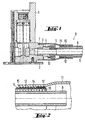
- Figure 1 shows in a section a fitting 1, for example screwed with the help of a plate 2 to a wall under plaster can be.
- a side Nipple 3 is formed, which has an internal thread.
- another nipple 4 screwed in, and although with the interposition of a seal, not shown.
- a union nut 5 a Water pipe 6 connected. It can be a supply line to act for cold or hot water, or even to take away Line, for example, to a shower outlet or a bath enema.
- nipple 3 On the nipple 3, in which the nipple 4 is screwed is on the circular cylindrical outer surface a circumferential groove. 7 present, in which an O-ring to the seal are inserted can.
- the lateral surface of the nipple 3 is also with provided an external thread.
- a protective hose 8 is pushed over the water pipe, which is formed as a corrugated tube 9 and on the valve 1 associated end 10 an end sleeve 11 is attached.
- the ferrule 11 has a first cylindrical portion 12 whose inner diameter is approximately equal to the outer diameter of the Corrugated tube 9 corresponds. Subsequently expanded the ferrule 11 in a second section 13, the like is dimensioned that the nipple 4 and the nut 5 have space in it. The free end of this section 13 is provided with an internal thread that matches the external thread of Nipples 3 interacts.
- the ferrule is under liner a seal, not shown, arranged in the groove 7 screwed on the nipple 3 in the form of an O-ring.
- the Connection between the ferrule and the corrugated tube 9 is also sealed, so that around the port of the Water pipe 6 a space is created, which seals to the outside is. If from the screw of the water pipe 6 Water leaking, this can only be in the room inside the Protective tube 8 arrive.
- FIG. 2 shows, on an enlarged scale, the arrangement of the connection between the corrugated tube 9 and the ferrule 11.
- Der Area 12 of the ferrule 11 with the reduced about the Outer diameter of the corrugated tube 9 corresponding inner diameter points approximately in half of its axial extent a shoulder 14 on.
- the between the free end 15 of the section 12 of the ferrule and the shoulder 14 existing area has an inner diameter that is the outer diameter of the corrugated hose 9 is the same.
- a seal in the form of an O-ring 17 is used.
- the O-rings are slightly larger than the wave troughs 16 of the corrugated hose 9, so that they are radial over the outside of the Corrugated tube 9 protrude. If you pull on the corrugated hose 9 in Figure 2 to the left, or at the ferrule to the right, to to try the end sleeve 11 of the corrugated tube. 9 remove, so get the O-rings 17 to rest on the Shoulder 14. Next, the ferrule 11 is not of the Remove corrugated hose 9.
- a corrugated hose is in the correct order by a End sleeve pushed through until its end from the widened Section 13 stands out.
- the Corrugated hose 9 retracted until the 3 O-rings in the narrower part 12 of the ferrule lie in the just described Way.
- the corrugated tube 9 with for example, a ferrule at both ends to the water line pushed on and screwed on the fitting on the nipple 3. If the water pipe at the other end in similar Way is screwed to a fitting, during screwing the protective tube to be compressed through the corrugated tube 9 is possible. Subsequently, the there end sleeve 11 are screwed.
- the tight connection between the ferrule 11 and the corrugated hose can also be done after screwing on the ferrule, if torsions of the corrugated hose 9 are prevented should.
Landscapes
- Life Sciences & Earth Sciences (AREA)
- Engineering & Computer Science (AREA)
- Hydrology & Water Resources (AREA)
- Public Health (AREA)
- Water Supply & Treatment (AREA)
- Health & Medical Sciences (AREA)
- Domestic Plumbing Installations (AREA)
- Joining Of Building Structures In Genera (AREA)
- Joints That Cut Off Fluids, And Hose Joints (AREA)
- Dowels (AREA)
- Mutual Connection Of Rods And Tubes (AREA)
- Laying Of Electric Cables Or Lines Outside (AREA)
- Non-Disconnectible Joints And Screw-Threaded Joints (AREA)
- Pipe Accessories (AREA)
- Connecting Device With Holders (AREA)
- Non-Portable Lighting Devices Or Systems Thereof (AREA)
- Fastening Of Light Sources Or Lamp Holders (AREA)
- Joints Allowing Movement (AREA)
Abstract
Description
Es ist bekannt, Armaturen so anzuordnen, dass der Armaturenkörper mit den an ihm angeschlossenen Wasserleitungen unter Putz liegt. Dabei kann es zum Austreten von Leckwasser kommen.It is known to arrange fittings so that the fitting body with the water pipes connected to it below Plaster is located. It may leak water come.
Es ist bereits eine Installation zur Durchleitung von Flüssigkeiten bekannt (CH-A5-662632), bei der der Leitungsschlauch von einem Schutzschlauch umgeben ist, der im Bereich seines Endes einen zweiteiligen Haltekäfig aufweist. Dieser Haltekäfig wird radial zusammengesetzt und bildet dadurch eine Endabdeckung, die aus der Anschlussverschraubung möglicherweise austretendes Wasser in den Schutzschlauch ableitet.An installation for the passage of liquids is already known (CH-A5-662632), in which the conduit hose is surrounded by a protective tube, the has a two-part holding cage in the region of its end. This holding cage is radially assembled and thereby forms an end cap, which is made of the connection fitting possibly leaking water into the protective tube derives.
Weiterhin bekannt ist eine Einrichtung zur Verbindung einer flexiblen Kunststoff-Doppelrohrleitung mit einem Gebrauchswasserverbraucher. Mit dem Verbraucher wird eine Endhülse verbunden, die die innere und äußere Rohrleitung umgibt. Das freie Ende der Endhülse ist als Dichtung ausgebildet, die an der Außenseite des äußeren Rohrs anliegt. Ein Herausziehen des äußeren Rohrs kann dabei nicht verhindert werden (EP 805299).Also known is a device for connecting a flexible plastic double pipe with a consumer water consumer. With the consumer an end sleeve is connected which surrounds the inner and outer tubing. The free end of the end sleeve is designed as a seal, which is on the outside of the outer Pipe rests. Pulling out the outer tube can not be prevented be (EP 805299).
Der Erfindung liegt die Aufgabe zugrunde, eine Anordnung zum Anschließen einer Armatur zu schaffen, bei der möglicherweise auftretendes Leckwasser unschädlich gemacht wird.The invention has for its object to provide an arrangement for Connecting a faucet to create, possibly occurring leak water is rendered harmless.
Zur Lösung dieser Aufgabe schlägt die Erfindung eine Anordnung mit den Merkmalen des Anspruchs 1 vor. Weiterbildungen der Erfindung sind Gegenstand der abhängigen Ansprüche, deren Wortlaut durch Bezugnahme zum Inhalt der Beschreibung gemacht wird.To solve this problem, the invention proposes an arrangement with the features of claim 1 before. further developments The invention are the subject of the dependent claims, whose Wording Reference is made to the content of the description.
Nach wie vor kann die Armatur unter Putz angeordnet und mit den Leitungen verbunden werden. Jedoch wird jetzt über die Wasserleitung ein Schutzschlauch geschoben oder gezogen, der selbst an der Armatur angebracht wird, wobei dieser Schutzschlauch die Wasserleitung umgibt. Falls Leckwasser auftritt, gelangt dieses in den Raum zwischen dem Schutzschlauch und der Wasserleitung und damit nicht in das Mauerwerk. As before, the fitting can be arranged under plaster and with be connected to the lines. However, now about the Water pipe pushed or pulled a protective hose, the itself attached to the fitting, this protective hose surrounding the water pipe. If leakage occurs, this gets into the space between the protective tube and the water pipe and thus not in the masonry.
Zur Befestigung des Schutzschlauchs an der Armatur ist erfindungsgemäß in Weiterbildung vorgesehen, dass der Schutzschlauch an seinem der Armatur zugeordneten Ende eine Endhülse aufweist, die an dem Anschluss der Armatur angeschlossen wird und den Anschluss für die Wasserleitung umgibt, vorzugsweise mit Abstand von diesem. Die Endhülse kann beispielsweise starr sein und aus Kunststoff bestehen. Sie kann beispielsweise unter Zwischenlage eines Dichtrings an der Armatur angeschraubt werden.To attach the protective tube to the valve is according to the invention provided in continuing education that the Protective hose at its end associated with the fitting End sleeve having connected to the connection of the valve and surrounds the connection for the water pipe, preferably at a distance from this. The end sleeve can for example, be rigid and made of plastic. she For example, with the interposition of a sealing ring the fitting are screwed on.
Erfindungsgemäß kann vorgesehen sein, dass der Schutzschlauch unabhängig von der Wasserleitung anschließbar ist.According to the invention, it may be provided that the protective hose independent of the water line can be connected.
Zur Erleichterung des Anbringens des Schutzschlauches kann erfindungsgemäß vorgesehen sein, dass dieser mindestens teilweise dehnbar und/oder stauchbar ist.To facilitate the attachment of the protective tube can be provided according to the invention that this at least partially stretchable and / or compressible.
Erfindungsgemäß kann in Weiterbildung auch vorgesehen sein, dass der Schutzschlauch mindestens teilweise biegsam ist.According to the invention, training may also be provided for that the protective tube is at least partially flexible.
In nochmaliger Weiterbildung der Erfindung kann vorgesehen sein, dass der Schutzschlauch leicht abzutrennen ist, beispielsweise mit Hilfe eines Messers.In a further development of the invention can be provided be that the protective tube is easy to separate, for example with the help of a knife.
Die Erfindung schlägt vor, dass die Endhülse von dem Schutzschlauch ziehbar und/oder auf den Schutzschlauch aufschiebbar ausgebildet ist.The invention proposes that the end sleeve of the protective tube can be pulled and / or pushed onto the protective hose is trained.
Erfindungsgemäß ist vorgesehen, dass die Verbindung zwischen dem Schutzschlauch und der Endhülse durch eine getrennte Dichtung abgedichtet ist.According to the invention it is provided that the compound between the protective tube and the ferrule by a sealed separate seal.
Hierzu weist die Endhülse eine Schulter bzw. eine Verringerung ihres Innendurchmessers auf, an der die mit dem Schutzschlauch verbundene Dichtung zur Anlage gelangt, so dass sie auf diese Weise das Herausziehen des Schutzschlauches aus der Hülse bzw. das Abziehen der Endhülse von dem Schlauch verhindert.For this purpose, the ferrule has a shoulder or a reduction on their inside diameter, on the one with the protective tube connected gasket comes to rest, allowing them in this way, the withdrawal of the protective tube from the Sleeve or the removal of the ferrule of the hose prevented.
Die Dichtung kann beispielsweise auf den Schutzschlauch aufgeklebt sein.The seal can, for example, on the protective tube be glued on.
Als besonders günstig hat es sich herausgestellt, dass nach einem weiteren Merkmale der Erfindung der Schutzschlauch mindestens teilweise als ein Wellschlauch ausgebildet sein kann. Ein solcher Wellschlauch ist sowohl dehnbar als auch stauchbar und biegsam.As particularly favorable, it has been found that after Another feature of the invention, the protective tube be at least partially formed as a corrugated hose can. Such a corrugated tube is both stretchable and compressible and flexible.
Zur Abdichtung zwischen der Endhülse und dem Wellschlauch kann vorgesehen sein, dass als Dichtung eine Formdichtung verwendet wird, die in die Vertiefung des Wellschlauches eingesetzt wird, im einfachsten Fall beispielsweise ein oder mehrere O-Ringe.For sealing between the ferrule and the corrugated hose can be provided that a gasket as a molded seal used in the recess of the corrugated tube is used, in the simplest case, for example, a or several O-rings.
Die Endhülse kann beispielsweise unter Zwischenlage eines O-Rings auf die Armatur aufgeschraubt werden.The ferrule can, for example, with the interposition of a O-rings are screwed onto the fitting.
Weitere Merkmale, Einzelheiten und Vorzüge der Erfindung ergeben sich aus der folgenden Beschreibung einer bevorzugten Ausführungsform der Erfindung sowie anhand der Zeichnung. Hierbei zeigen:
- Fig. 1
- einen Teilschnitt durch eine Armatur mit einer über einen Schraubanschluss angeschlossenen Wasserleitung und einem Schutzschlauch;
- Fig. 2
- in vergrößertem Maßstab die Abdichtung zwischen einer Endhülse und dem als Wellschlauch ausgebildeten Schutzschlauch.
- Fig. 1
- a partial section through a fitting with a connected via a screw water pipe and a protective hose;
- Fig. 2
- on an enlarged scale, the seal between an end sleeve and the protective tube designed as a corrugated hose.
Figur 1 zeigt in einem Schnitt eine Armatur 1, die beispielsweise
mit Hilfe einer Platte 2 an einer Wand unter Putz angeschraubt
werden kann. An der Armatur 1 ist seitlich ein
Nippel 3 ausgebildet, der ein Innengewinde aufweist. In das
Innengewinde ist ein weiterer Nippel 4 eingeschraubt, und
zwar unter Zwischenlage einer nicht dargestellten Dichtung.
An diesem Nippel 4 ist mit Hilfe einer Überwurfmutter 5 eine
Wasserleitung 6 angeschlossen. Es kann sich um eine Zuleitung
für kaltes oder warmes Wasser handeln, oder auch um eine wegführenden
Leitung, die beispielsweise zu einem Brauseabgang
oder einem Wanneneinlauf führt.Figure 1 shows in a section a fitting 1, for example
screwed with the help of a
An dem Nippel 3, in den der Nippel 4 eingeschraubt ist, ist
an der kreiszylindrischem Außenfläche eine umlaufende Nut 7
vorhanden, in die ein O-Ring zur Dichtung eingelegt werden
kann. Die Mantelfläche des Nippels 3 ist darüber hinaus mit
einem Außengewinde versehen.On the
Über die Wasserleitung ist ein Schutzschlauch 8 geschoben,
der als Wellschlauch 9 ausgebildet ist und an dessen der Armatur
1 zugeordneten Ende 10 eine Endhülse 11 angebracht ist.
Die Endhülse 11 weist einen ersten zylindrischen Abschnitt 12
auf, dessen Innendurchmesser etwa dem Außendurchmesser des
Wellschlauches 9 entspricht. Daran anschließend erweitert
sich die Endhülse 11 in einen zweiten Abschnitt 13, der so
dimensioniert ist, dass der Nippel 4 und die Überwurfmutter 5
in ihm Platz haben. Das freie Ende dieses Abschnitts 13 ist
mit einem Innengewinde versehen, das mit dem Außengewinde des
Nippels 3 zusammenwirkt. Die Endhülse ist unter Zwischenlage
einer nicht dargestellten in der Nut 7 angeordneten Dichtung
in Form eines O-Rings auf den Nippel 3 aufgeschraubt. Die
Verbindung zwischen der Endhülse und dem Wellschlauch 9 ist
ebenfalls abgedichtet, so dass rings um den Anschluss der
Wasserleitung 6 ein Raum entsteht, der nach außen abgedichtet
ist. Falls aus der Schraubverbindung der Wasserleitung 6
Wasser austritt, kann dieses nur in den Raum innerhalb des
Schutzschlauchs 8 gelangen.A
Figur 2 zeigt in vergrößertem Maßstab die Anordnung der Verbindung
zwischen dem Wellschlauch 9 und der Endhülse 11. Der
Bereich 12 der Endhülse 11 mit dem verringerten etwa dem
Außendurchmesser des Wellschlauches 9 entsprechenden Innendurchmesser
weist etwa in der Hälfte seiner Axialerstreckung
eine Schulter 14 auf. Der zwischen dem freien Ende 15 des Abschnitts
12 der Endhülse und der Schulter 14 vorhandene Bereich
weist einen Innendurchmesser auf, der dem Außendurchmesser
des Wellschlauches 9 gleich ist.FIG. 2 shows, on an enlarged scale, the arrangement of the connection
between the
In die drei ersten Wellentäler 16 des Wellschlauches ist jeweils
eine Dichtung in Form eines O-Rings 17 eingesetzt. Die
O-Ringe sind etwas größer als die Wellentäler 16 des Wellschlauches
9, so dass sie radial über die Außenseite des
Wellschlauches 9 vorstehen. Zieht man an dem Wellschlauch 9
in Figur 2 nach links, oder an der Endhülse nach rechts, um
den Versuch zu machen, die Endhülse 11 von dem Wellschlauch 9
abzuziehen, so gelangen die O-Ringe 17 zur Anlage an der
Schulter 14. Weiter lässt sich die Endhülse 11 nicht von dem
Wellschlauch 9 abziehen. In the first three
Die Anbringung der in den Figuren 1 und 2 dargestellten Anordnung
geschieht folgendermaßen. Beispielsweise wird die
Wasserleitung 6 an der Armatur 1 in der herkömmlicher Weise
angeschlossen. Das gegenüberliegenden Ende der Wasserleitung
ist noch frei.The attachment of the arrangement shown in Figures 1 and 2
happens as follows. For example, the
Ein Wellschlauch wird in der richtigen Reihenfolge durch eine
Endhülse durchgeschoben, bis sein Ende aus dem verbreiterten
Abschnitt 13 herausragt. Dort werden drei O-Ringe 17 in die
drei ersten Wellentäler 16 des Wellschlauches 9 eingelegt.
Sie liegen dort unter einer gewissen Spannung. Dann wird der
Wellschlauch 9 zurückgezogen, bis die 3 O-Ringe in den
schmaleren Teil 12 der Endhülse liegen, in der gerade beschriebenen
Art und Weise. Dann wird der Wellschlauch 9 mit
beispielsweise einer Endhülse an beiden Enden auf die Wasserleitung
aufgeschoben und an der Armatur auf den Nippel 3 aufgeschraubt.
Wenn die Wasserleitung am anderen Ende in ähnlicher
Weise an einer Armatur angeschraubt wird, kann während
des Einschraubens der Schutzschlauch gestaucht werden, was
durch den Wellschlauch 9 möglich ist. Anschließend kann die
dortige Endhülse 11 aufgeschraubt werden.A corrugated hose is in the correct order by a
End sleeve pushed through until its end from the
Das dichte Verbinden zwischen der Endhülse 11 und dem Wellschlauch
kann auch nach dem Aufschrauben der Endhülse erfolgen,
wenn Torsionen des Wellschlauches 9 verhindert werden
sollen.The tight connection between the
Claims (9)
- Arrangement to connect a fitting, especially a concealed fitting with:a water line (6),a connection (3, 4, 5) for the water line (6),a protective tube (8), whichsurrounds the water line (6), includinga connection for the protective tube (8), wherebythe protective tube (8) has an end sleeve (11), whichis connected to the connection of the fitting for the protective tube (8),and surrounds the connection (3, 4, 5) for the water line (6), preferably at a distance from the water line, andcan be pulled off of the protective tube (8) and/or shoved onto the flexible tube, characterized in that,the end sleeve (11) is sealed against the protective tube (8) by a seal (17), andhas a shoulder (14) or reduction of the inner diameter on which the seal connected to the protective tube (8) rests.
- Arrangement according to claim 1, wherein the protective tube (8) can be connected independent of the water line (6).
- Arrangement according to one of the prior claims, wherein the protective tube (8) has at least some expandable sections.
- Arrangement according to one of the prior claims, wherein the protective tube (8) is at least partially flexible.
- Arrangement according to one of the prior claims, wherein the protective tube (8) can be easily disconnected.
- Arrangement according to one of the prior claims, wherein the seal (17) is glued onto the protective tube (8).
- Arrangement according to one of the prior claims, wherein the protective tube (8) is at least partially made of corrugated hose (9).
- Arrangement according to claim 7, wherein the seal (17) is a shaped seal, possibly an O-ring, inserted into the recesses (16) of the corrugated hose (9).
- Arrangement according to one of the prior claims, wherein the end sleeve (11) is screwed onto the fitting.
Priority Applications (1)
| Application Number | Priority Date | Filing Date | Title |
|---|---|---|---|
| DK00104987T DK1036972T3 (en) | 1999-03-12 | 2000-03-09 | Device for connecting a luminaire |
Applications Claiming Priority (2)
| Application Number | Priority Date | Filing Date | Title |
|---|---|---|---|
| DE19911065 | 1999-03-12 | ||
| DE19911065A DE19911065A1 (en) | 1999-03-12 | 1999-03-12 | Arrangement for connecting a valve |
Publications (3)
| Publication Number | Publication Date |
|---|---|
| EP1036972A2 EP1036972A2 (en) | 2000-09-20 |
| EP1036972A3 EP1036972A3 (en) | 2001-10-10 |
| EP1036972B1 true EP1036972B1 (en) | 2005-07-27 |
Family
ID=7900748
Family Applications (1)
| Application Number | Title | Priority Date | Filing Date |
|---|---|---|---|
| EP00104987A Expired - Lifetime EP1036972B1 (en) | 1999-03-12 | 2000-03-09 | Connection arrangement for a fitting |
Country Status (4)
| Country | Link |
|---|---|
| EP (1) | EP1036972B1 (en) |
| AT (1) | ATE300697T1 (en) |
| DE (2) | DE19911065A1 (en) |
| DK (1) | DK1036972T3 (en) |
Families Citing this family (2)
| Publication number | Priority date | Publication date | Assignee | Title |
|---|---|---|---|---|
| DE102007044284A1 (en) | 2007-09-07 | 2009-03-12 | Hansgrohe Ag | Connection arrangement e.g. for connecting sanitary fitting, has water pipe and arranged at end with plumbing fitting, and water supply surrounds protection hose as well as end sleeve |
| DE202015102336U1 (en) * | 2015-05-07 | 2015-05-27 | Frank Bernhard | System for avoiding water damage |
Family Cites Families (7)
| Publication number | Priority date | Publication date | Assignee | Title |
|---|---|---|---|---|
| DE8212628U1 (en) * | 1982-05-03 | 1982-09-23 | TA Rokal GmbH, 4054 Nettetal | CONNECTION BOX FOR A WATER PIPING SYSTEM |
| CH662632A5 (en) * | 1984-03-26 | 1987-10-15 | Fischer Ag Georg | Installation for passing fluids through |
| DE8806346U1 (en) * | 1988-05-13 | 1988-07-28 | Thyssen Polymer Gmbh, 8000 Muenchen, De | |
| DE4243737C1 (en) * | 1992-12-23 | 1994-03-17 | Hansa Metallwerke Ag | Seal for double tube in sanitary appliance housing - has internal sealing lip engaging on core tube to seal space between tubes |
| DE9319297U1 (en) * | 1993-12-16 | 1994-02-24 | Kottmann Nachf Gebr Gosla Gmbh | Connection device on a helically formed metal hose |
| CH690551A5 (en) * | 1996-04-29 | 2000-10-13 | Geberit Technik Ag | Protective sleeve for flexible pipe connector fitting |
| DE59705840D1 (en) * | 1996-04-29 | 2002-01-31 | Jrg Gunzenhauser Ag Sissach | Device for connecting a flexible plastic double pipe with a consumer water consumer |
-
1999
- 1999-03-12 DE DE19911065A patent/DE19911065A1/en not_active Withdrawn
-
2000
- 2000-03-09 EP EP00104987A patent/EP1036972B1/en not_active Expired - Lifetime
- 2000-03-09 DK DK00104987T patent/DK1036972T3/en active
- 2000-03-09 AT AT00104987T patent/ATE300697T1/en not_active IP Right Cessation
- 2000-03-09 DE DE50010792T patent/DE50010792D1/en not_active Expired - Fee Related
Also Published As
| Publication number | Publication date |
|---|---|
| DK1036972T3 (en) | 2005-10-17 |
| DE19911065A1 (en) | 2000-09-14 |
| DE50010792D1 (en) | 2005-09-01 |
| ATE300697T1 (en) | 2005-08-15 |
| EP1036972A3 (en) | 2001-10-10 |
| EP1036972A2 (en) | 2000-09-20 |
Similar Documents
| Publication | Publication Date | Title |
|---|---|---|
| DE69919526T2 (en) | VICE CONNECTION AND SCREW MUFFS FOR THIS | |
| EP2807417B1 (en) | Method for connecting a connection piece to a thermally insulated conduit pipe | |
| AT410706B (en) | CONNECTING DEVICE FOR A PLASTIC PIPE | |
| EP0975914B1 (en) | Threaded branching for thin-walled channel pipes | |
| EP1036972B1 (en) | Connection arrangement for a fitting | |
| CH669828A5 (en) | ||
| DE102007044284A1 (en) | Connection arrangement e.g. for connecting sanitary fitting, has water pipe and arranged at end with plumbing fitting, and water supply surrounds protection hose as well as end sleeve | |
| DE4243737C1 (en) | Seal for double tube in sanitary appliance housing - has internal sealing lip engaging on core tube to seal space between tubes | |
| DE2427637A1 (en) | CONNECTION SLEEVE | |
| DE4240816A1 (en) | Plastics hose with connector for hand shower head - has plastics nipple with evenly spaced axially parallel webs deforming hose surface ensuring water-tight connection with associated metal sleeve. | |
| DE3221518C2 (en) | Fittings for the automatic connection of lines in pneumatic or hydraulic circuits | |
| DE10326300B4 (en) | Sanitary hose with rotatable coupling for a connection piece | |
| DE10320997B4 (en) | Valve tapping machine | |
| CH650578A5 (en) | TUBE CONNECTION FOR CONCENTRIC TUBES. | |
| DE2412697A1 (en) | PIPE CONNECTION | |
| DE2401035A1 (en) | Connection for coiled pipe for hand showers - has reinforcing bush threaded into end portion of pipe | |
| EP0709611B1 (en) | Insertion device for a gas pipe in a building | |
| DE19511537A1 (en) | Component for a hydraulic or pneumatic system and for fluids in general, for example a tap, a row fitting, a corner fitting, a 3-way or multi-way fitting | |
| DE3110923A1 (en) | Domestic gas connecting device | |
| DE4125426A1 (en) | Combined metal-plastic pipe for bathroom hand-held shower - has plastic-and surrounding spiral metal-pipes joined at shower-head end using plastic nipples to exert squeezing pressure on tube walls | |
| DE2909936A1 (en) | Elastic tube for use in food industry - with telescopic joint between inner and outer tube sealed by O=ring | |
| DE102011003864B4 (en) | Use for the water outlet from a sanitary fitting | |
| DE60216093T2 (en) | pipe connection | |
| EP0780523B1 (en) | Mixing valve with inclined mounted supply conduit | |
| DE3810097C1 (en) | Transition piece |
Legal Events
| Date | Code | Title | Description |
|---|---|---|---|
| PUAI | Public reference made under article 153(3) epc to a published international application that has entered the european phase |
Free format text: ORIGINAL CODE: 0009012 |
|
| AK | Designated contracting states |
Kind code of ref document: A2 Designated state(s): AT BE CH CY DE DK ES FI FR GB GR IE IT LI LU MC NL PT SE |
|
| AX | Request for extension of the european patent |
Free format text: AL;LT;LV;MK;RO;SI |
|
| PUAL | Search report despatched |
Free format text: ORIGINAL CODE: 0009013 |
|
| RIC1 | Information provided on ipc code assigned before grant |
Free format text: 7F 16L 35/00 A, 7E 03C 1/02 B, 7E 03C 1/042 B |
|
| AK | Designated contracting states |
Kind code of ref document: A3 Designated state(s): AT BE CH CY DE DK ES FI FR GB GR IE IT LI LU MC NL PT SE |
|
| AX | Request for extension of the european patent |
Free format text: AL;LT;LV;MK;RO;SI |
|
| 17P | Request for examination filed |
Effective date: 20020205 |
|
| AKX | Designation fees paid |
Free format text: AT BE CH CY DE DK ES FI FR GB GR IE IT LI LU MC NL PT SE |
|
| 17Q | First examination report despatched |
Effective date: 20030606 |
|
| GRAP | Despatch of communication of intention to grant a patent |
Free format text: ORIGINAL CODE: EPIDOSNIGR1 |
|
| GRAS | Grant fee paid |
Free format text: ORIGINAL CODE: EPIDOSNIGR3 |
|
| GRAA | (expected) grant |
Free format text: ORIGINAL CODE: 0009210 |
|
| REG | Reference to a national code |
Ref country code: SE Ref legal event code: TRGR |
|
| AK | Designated contracting states |
Kind code of ref document: B1 Designated state(s): AT BE CH CY DE DK ES FI FR GB GR IE IT LI LU MC NL PT SE |
|
| PG25 | Lapsed in a contracting state [announced via postgrant information from national office to epo] |
Ref country code: IT Free format text: LAPSE BECAUSE OF FAILURE TO SUBMIT A TRANSLATION OF THE DESCRIPTION OR TO PAY THE FEE WITHIN THE PRESCRIBED TIME-LIMIT;WARNING: LAPSES OF ITALIAN PATENTS WITH EFFECTIVE DATE BEFORE 2007 MAY HAVE OCCURRED AT ANY TIME BEFORE 2007. THE CORRECT EFFECTIVE DATE MAY BE DIFFERENT FROM THE ONE RECORDED. Effective date: 20050727 Ref country code: GB Free format text: LAPSE BECAUSE OF FAILURE TO SUBMIT A TRANSLATION OF THE DESCRIPTION OR TO PAY THE FEE WITHIN THE PRESCRIBED TIME-LIMIT Effective date: 20050727 Ref country code: NL Free format text: LAPSE BECAUSE OF FAILURE TO SUBMIT A TRANSLATION OF THE DESCRIPTION OR TO PAY THE FEE WITHIN THE PRESCRIBED TIME-LIMIT Effective date: 20050727 Ref country code: IE Free format text: LAPSE BECAUSE OF FAILURE TO SUBMIT A TRANSLATION OF THE DESCRIPTION OR TO PAY THE FEE WITHIN THE PRESCRIBED TIME-LIMIT Effective date: 20050727 |
|
| REG | Reference to a national code |
Ref country code: GB Ref legal event code: FG4D Free format text: NOT ENGLISH |
|
| REG | Reference to a national code |
Ref country code: CH Ref legal event code: EP |
|
| REG | Reference to a national code |
Ref country code: IE Ref legal event code: FG4D Free format text: LANGUAGE OF EP DOCUMENT: GERMAN |
|
| REF | Corresponds to: |
Ref document number: 50010792 Country of ref document: DE Date of ref document: 20050901 Kind code of ref document: P |
|
| REG | Reference to a national code |
Ref country code: DK Ref legal event code: T3 |
|
| PG25 | Lapsed in a contracting state [announced via postgrant information from national office to epo] |
Ref country code: GR Free format text: LAPSE BECAUSE OF FAILURE TO SUBMIT A TRANSLATION OF THE DESCRIPTION OR TO PAY THE FEE WITHIN THE PRESCRIBED TIME-LIMIT Effective date: 20051027 |
|
| PG25 | Lapsed in a contracting state [announced via postgrant information from national office to epo] |
Ref country code: ES Free format text: LAPSE BECAUSE OF FAILURE TO SUBMIT A TRANSLATION OF THE DESCRIPTION OR TO PAY THE FEE WITHIN THE PRESCRIBED TIME-LIMIT Effective date: 20051107 |
|
| PG25 | Lapsed in a contracting state [announced via postgrant information from national office to epo] |
Ref country code: PT Free format text: LAPSE BECAUSE OF FAILURE TO SUBMIT A TRANSLATION OF THE DESCRIPTION OR TO PAY THE FEE WITHIN THE PRESCRIBED TIME-LIMIT Effective date: 20051227 |
|
| NLV1 | Nl: lapsed or annulled due to failure to fulfill the requirements of art. 29p and 29m of the patents act | ||
| GBV | Gb: ep patent (uk) treated as always having been void in accordance with gb section 77(7)/1977 [no translation filed] |
Effective date: 20050727 |
|
| REG | Reference to a national code |
Ref country code: IE Ref legal event code: FD4D |
|
| PG25 | Lapsed in a contracting state [announced via postgrant information from national office to epo] |
Ref country code: AT Free format text: LAPSE BECAUSE OF NON-PAYMENT OF DUE FEES Effective date: 20060309 |
|
| PG25 | Lapsed in a contracting state [announced via postgrant information from national office to epo] |
Ref country code: LI Free format text: LAPSE BECAUSE OF NON-PAYMENT OF DUE FEES Effective date: 20060331 Ref country code: MC Free format text: LAPSE BECAUSE OF NON-PAYMENT OF DUE FEES Effective date: 20060331 Ref country code: BE Free format text: LAPSE BECAUSE OF NON-PAYMENT OF DUE FEES Effective date: 20060331 Ref country code: LU Free format text: LAPSE BECAUSE OF NON-PAYMENT OF DUE FEES Effective date: 20060331 Ref country code: CH Free format text: LAPSE BECAUSE OF NON-PAYMENT OF DUE FEES Effective date: 20060331 |
|
| PLBE | No opposition filed within time limit |
Free format text: ORIGINAL CODE: 0009261 |
|
| STAA | Information on the status of an ep patent application or granted ep patent |
Free format text: STATUS: NO OPPOSITION FILED WITHIN TIME LIMIT |
|
| 26N | No opposition filed |
Effective date: 20060428 |
|
| EN | Fr: translation not filed | ||
| PG25 | Lapsed in a contracting state [announced via postgrant information from national office to epo] |
Ref country code: FR Free format text: LAPSE BECAUSE OF FAILURE TO SUBMIT A TRANSLATION OF THE DESCRIPTION OR TO PAY THE FEE WITHIN THE PRESCRIBED TIME-LIMIT Effective date: 20060922 |
|
| REG | Reference to a national code |
Ref country code: CH Ref legal event code: PL |
|
| BERE | Be: lapsed |
Owner name: HANSGROHE A.G. Effective date: 20060331 |
|
| PG25 | Lapsed in a contracting state [announced via postgrant information from national office to epo] |
Ref country code: CY Free format text: LAPSE BECAUSE OF FAILURE TO SUBMIT A TRANSLATION OF THE DESCRIPTION OR TO PAY THE FEE WITHIN THE PRESCRIBED TIME-LIMIT Effective date: 20050727 Ref country code: FR Free format text: LAPSE BECAUSE OF FAILURE TO SUBMIT A TRANSLATION OF THE DESCRIPTION OR TO PAY THE FEE WITHIN THE PRESCRIBED TIME-LIMIT Effective date: 20050727 |
|
| PGFP | Annual fee paid to national office [announced via postgrant information from national office to epo] |
Ref country code: DK Payment date: 20090321 Year of fee payment: 10 |
|
| PGFP | Annual fee paid to national office [announced via postgrant information from national office to epo] |
Ref country code: FI Payment date: 20090325 Year of fee payment: 10 |
|
| PGFP | Annual fee paid to national office [announced via postgrant information from national office to epo] |
Ref country code: SE Payment date: 20090325 Year of fee payment: 10 Ref country code: DE Payment date: 20090417 Year of fee payment: 10 |
|
| EUG | Se: european patent has lapsed | ||
| REG | Reference to a national code |
Ref country code: DK Ref legal event code: EBP |
|
| PG25 | Lapsed in a contracting state [announced via postgrant information from national office to epo] |
Ref country code: FI Free format text: LAPSE BECAUSE OF NON-PAYMENT OF DUE FEES Effective date: 20100309 |
|
| PG25 | Lapsed in a contracting state [announced via postgrant information from national office to epo] |
Ref country code: DE Free format text: LAPSE BECAUSE OF NON-PAYMENT OF DUE FEES Effective date: 20101001 |
|
| PG25 | Lapsed in a contracting state [announced via postgrant information from national office to epo] |
Ref country code: DK Free format text: LAPSE BECAUSE OF NON-PAYMENT OF DUE FEES Effective date: 20100331 |
|
| PG25 | Lapsed in a contracting state [announced via postgrant information from national office to epo] |
Ref country code: SE Free format text: LAPSE BECAUSE OF NON-PAYMENT OF DUE FEES Effective date: 20100310 |