EP1036735A2 - Ausstossmechanismus für Satelliten - Google Patents
Ausstossmechanismus für Satelliten Download PDFInfo
- Publication number
- EP1036735A2 EP1036735A2 EP00103848A EP00103848A EP1036735A2 EP 1036735 A2 EP1036735 A2 EP 1036735A2 EP 00103848 A EP00103848 A EP 00103848A EP 00103848 A EP00103848 A EP 00103848A EP 1036735 A2 EP1036735 A2 EP 1036735A2
- Authority
- EP
- European Patent Office
- Prior art keywords
- spring
- satellite
- spindle
- ejection
- payload
- Prior art date
- Legal status (The legal status is an assumption and is not a legal conclusion. Google has not performed a legal analysis and makes no representation as to the accuracy of the status listed.)
- Withdrawn
Links
- 230000007246 mechanism Effects 0.000 title claims abstract description 17
- 230000008878 coupling Effects 0.000 claims abstract description 5
- 238000010168 coupling process Methods 0.000 claims abstract description 5
- 238000005859 coupling reaction Methods 0.000 claims abstract description 5
- 238000005096 rolling process Methods 0.000 claims abstract description 5
- 230000033001 locomotion Effects 0.000 claims description 15
- 230000006835 compression Effects 0.000 claims description 6
- 238000007906 compression Methods 0.000 claims description 6
- 230000009467 reduction Effects 0.000 claims description 3
- 230000005540 biological transmission Effects 0.000 abstract description 2
- 239000002775 capsule Substances 0.000 description 10
- 238000000034 method Methods 0.000 description 9
- 230000008569 process Effects 0.000 description 9
- 238000012937 correction Methods 0.000 description 5
- 230000036316 preload Effects 0.000 description 4
- 238000010586 diagram Methods 0.000 description 3
- 230000000694 effects Effects 0.000 description 3
- 230000008901 benefit Effects 0.000 description 2
- 239000000725 suspension Substances 0.000 description 2
- 230000001133 acceleration Effects 0.000 description 1
- 230000008859 change Effects 0.000 description 1
- 238000006243 chemical reaction Methods 0.000 description 1
- 230000001419 dependent effect Effects 0.000 description 1
- 238000006073 displacement reaction Methods 0.000 description 1
- 230000002996 emotional effect Effects 0.000 description 1
- 238000005516 engineering process Methods 0.000 description 1
- 210000003746 feather Anatomy 0.000 description 1
- 230000005484 gravity Effects 0.000 description 1
- 238000005259 measurement Methods 0.000 description 1
- 230000003134 recirculating effect Effects 0.000 description 1
- 230000002040 relaxant effect Effects 0.000 description 1
- 238000000926 separation method Methods 0.000 description 1
- 238000009987 spinning Methods 0.000 description 1
- 230000001960 triggered effect Effects 0.000 description 1
- 238000004804 winding Methods 0.000 description 1
Images


Classifications
-
- B—PERFORMING OPERATIONS; TRANSPORTING
- B64—AIRCRAFT; AVIATION; COSMONAUTICS
- B64G—COSMONAUTICS; VEHICLES OR EQUIPMENT THEREFOR
- B64G1/00—Cosmonautic vehicles
- B64G1/22—Parts of, or equipment specially adapted for fitting in or to, cosmonautic vehicles
- B64G1/64—Systems for coupling or separating cosmonautic vehicles or parts thereof, e.g. docking arrangements
- B64G1/641—Interstage or payload connectors
- B64G1/642—Clamps, e.g. Marman clamps
-
- B—PERFORMING OPERATIONS; TRANSPORTING
- B64—AIRCRAFT; AVIATION; COSMONAUTICS
- B64G—COSMONAUTICS; VEHICLES OR EQUIPMENT THEREFOR
- B64G1/00—Cosmonautic vehicles
- B64G1/22—Parts of, or equipment specially adapted for fitting in or to, cosmonautic vehicles
- B64G1/64—Systems for coupling or separating cosmonautic vehicles or parts thereof, e.g. docking arrangements
- B64G1/645—Separators
- B64G1/6457—Springs; Shape memory actuators
-
- B—PERFORMING OPERATIONS; TRANSPORTING
- B64—AIRCRAFT; AVIATION; COSMONAUTICS
- B64G—COSMONAUTICS; VEHICLES OR EQUIPMENT THEREFOR
- B64G1/00—Cosmonautic vehicles
- B64G1/22—Parts of, or equipment specially adapted for fitting in or to, cosmonautic vehicles
- B64G1/64—Systems for coupling or separating cosmonautic vehicles or parts thereof, e.g. docking arrangements
- B64G1/645—Separators
- B64G1/6455—Pyrotechnics; Using heat
Definitions
- the invention relates to a spring operated Ejection mechanism for satellites.
- the payload capsules then move on one Descent towards the earth's surface where, depending on the purpose of the mission, either in the atmosphere burn up or land specifically to be salvaged afterwards to become.
- the sub-satellite itself is attached a long rope that connects this with the long-range station connects.
- the object of the invention is a device of type mentioned in such a way that it is possible is as simple and easy as possible Arrangement to change the direction of ejection of the payload and therefore particularly in the case of cable-coupled satellites to implement flexible exposure conditions. In particular, the repercussions on the suspect Satellites are kept as low as possible.
- the invention solves this problem by providing that with such a device a train and a Compression spring combined with each other and a non-self-locking Spindle are variably biased and that the bias of the springs over one with a Reduction geared electric motor is adjustable.
- the Springs provided according to the invention relaxes and the The usable mass is in the earth direction from the carrier missile flung out.
- the direction of ejection can be wide Areas over both the azimuth and the Elevation angle can be set.
- This Settings are according to the invention by a electric motor strongly translated into slow made, which is preferably a in the Robot technology uses so-called harmonic drive gear acts.
- the ejection mechanism according to the invention has the Advantage of a flexible application, since the The direction of the ejection force can be varied almost as desired is. It is therefore particularly suitable for Repatriation, the so-called de-orbitation, one Usable mass, for example a capsule Earth's surface, starting from a sub-satellite cable-coupled satellite system, the main satellite especially the planned international Space station ISS can be.
- the descent will be there significantly influenced by that at the time of ejection acting vector of the ejection force, which at the Device according to the invention is easily adjustable.
- the ejection mechanism according to the invention can just as advantageous for exposing one free flying satellites or a payload capsule be used.
- the planned ISS space station is suitable.
- the Output can be both towards the zenith, ie "after above “, as well as towards Nadir, i.e.” down " or directed towards the earth.
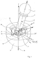
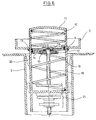
- the one shown in Figures 1 and 2 Ejection device for satellites consists of a to be blasted payload capsule 1, which has a Clamp connection 3 to a cylindrical housing 2 is flanged.
- the clamp connection 3 can by pyrotechnic detonators are released.
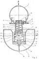
- One inside each of the housing 2 arranged compression spring 12 and tension spring 18 are supported on the one hand by a push-pull plate 14 and on the other hand on a spring sleeve 11.
- the feathers 12 and 18 are tensioned by a movement nut 22, which in turn has the spring sleeve 11 via a spindle 19 moved in the axial direction.
- the spindle 19 is from one with a reduction gear, one so-called harmonic drive, equipped electric motor 30 driven via a clutch 26, if one Disc brake 25 is released.
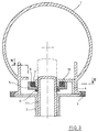
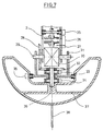
- the electric motor 30 is mounted in the pot housing 31 via an axis of rotation 29. about this axis of rotation 29 can the housing 2 and with this connected components by one Elevation angle El can be pivoted.
- the drive takes place by means of a motor shaft 36 via a Clutch 33 and a bevel gear pair 32, 28th
- the azimuth angle Az of the arrangement is determined by the Motor shaft 36 via a second clutch 34 set, provided a second disc brake 35 is solved.
- a sub-satellite 37 and a Pot housing 31 rotated against each other and then coupled to each other by means of the disc brake 35.
- the sub-satellite 37 and the ejection mechanism are over a rope 38 with one in the drawing not shown space station connected.
- the moving nut 22 during the Relaxation process of the springs 12, 18 around the Rotate spindle axis 19 as it has a radial bearing 23 and an axial bearing 24 with the spring sleeve 11 connected is. Press during this process switched on magnetic winding a the roller tappet c the lower on a spline profile Clutch disc against the force of the springs e after below, so that the toothing d disengages.
- the tappet rollers allow relative movement between the two coupling halves.
- the spindle 19 is during this relaxation process from the electric motor 30 through the clutch 26 is separated (see Fig. 1 + 2). It then rotates opposite to the direction of rotation of the motion nut 22.
- Fig. 6 shows that this is made possible by another radial bearing 17 and another Thrust bearing 16, both between a bearing body 15 and the train-pressure plate 14 are arranged.
- Fig. 7 shows that by a code disc 27, which with a on the housing of the Electric motor 30 arranged sensor cooperates, a measurement of the angle of rotation of the spindle 19 and thus the spring tension allows. Is also on this Read the disc of the set azimuth angle.
- the right-rotating electric motor 30 moves over the engaged clutch 26, the brake disc 25 and the spindle 19.
- the thread of this spindle 19 has such a steep incline that it is ensured that no self-locking occurs, d. that is, the spindle 19 can itself of the Movement nut 22 are set in rotation.
- the when tightened by the spindle 19 Movement nut 22 then moves in the direction of negative Z-axis of the arrangement (see Fig. 1).
- the compression spring 12 is compressed and at the same time the tension spring 18 is stretched, since both springs 12, 18 each with one end on the train-pressure plate 14 are fixed.
- Spring tension is the spindle 19 by means of Disc brake 25 fixed relative to the housing 2.
- the actual ejection operation requires one Contact of the payload 1 with the three-winged Pressure plate 4, which is produced in that previously the switching magnet 9 is actuated for coupling.
- the springs 12 and 18 relax, one occurs Left turn of the spindle including one half the clutch 26 on.
- the payload 1 should ultimately be moved clockwise. The consequence would be one Faulty alignment of the spring axis. But, that the moving nut on the bearings 23 and 24 of the spring sleeve 11 is separated, such disruptive feedback avoided.
- the axis of rotation 29 for rotating the force vector with the Elevation angle around the Y axis is fixed with the Motor housing 30 connected.
- the housing 2 of the Mechanism With the housing 2 of the Mechanism is firmly connected to a wheel 28 of the Bevel gear.
- the continuous motor shaft is over the clutch 26 is decoupled from the spindle 19 since a kink must be possible.
- About the engaged clutch 33 is thus the bevel gear 32 to rotate.
- the Clutch 34 is decoupled from sub-satellite 37.
- the disc brake 35 must be activated. Thus the azimuth setting is not changed.
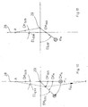
- FIGS. 10 and 11 illustrate the necessary correction of the elevation angle.
- the position of the total center of mass CM GES is determined by the centers of mass of the partial masses of the sub-satellite 37, CM SUB , the ejection mechanism 2, CM M , and the payload 1, CM N , defined.
- the setting to a desired elevation angle EL SOLL leads to a shift of CM GES .
- F GG sum of gravitational and centrifugal force
- An elevation angle error EL ERR occurs, which leads to an increase in the set elevation.
- a previous calculation of this error angle which is independent of the azimuth, then enables the required angle correction, as shown finally in FIG. 11.
- the series-connected springs 12 and 18 provide a resulting linear force-displacement spring characteristic.
- the spring force is proportional to the spindle rotation angle or the spindle revolutions.
- the spindle angle of rotation can be read with the code indexing disc 27 via photo elements.
- the prestressing force can thus be determined exactly.
- the relative azimuth angle ⁇ can be read from the relative part of the disc.
- the inertially valid angle only arises after a correction.
- the relative elevation angle can also be determined in this way, taking into account the transmission ratio of the bevel gear 28, 32.
- the inertially valid angle can only be specified after the correction has been made.
Landscapes
- Engineering & Computer Science (AREA)
- Remote Sensing (AREA)
- Aviation & Aerospace Engineering (AREA)
- Mechanical Engineering (AREA)
- Transmission Devices (AREA)
- Mechanical Operated Clutches (AREA)
Abstract
Description
- Fig. 1
- eine Prinzipdarstellung des Aufbaus einer Ausstoßvorrichtung für Satelliten,
- Fig. 2
- eine geschnittene Übersichtdarstellung der Anordnung gemäß Fig. 1,
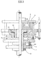
- Fig. 3 bis 7
- Detaildarstellungen einzelner Komponenten der Anordnung gemäß den Figuren 1 und 2 jeweils in geschnittener Darstellung und
- Fig. 8 bis 11
- Prinzipdarstellungen der Wirkungsweise der in den Figuren 1 bis 7 dargestellten Anordnung mit Darstellung von Störeinflüssen bei der Winkeleinstellung.
Für das Spannen der Vorrichtung vor dem Aussetzen der Nutzlast 1 muß zunächst gewährleistet sein, daß diese Nutzlast 1 mittels der Klemmverbindung 3, im Fall des hier dargestellten Ausführungsbeispiels einem sogenannten MARMAN-Spannband, fest mit dem Gehäuse 2 des Ausstoßmechanismus verbunden ist. Ein derartiger Spannvorgang kann aus konstruktiven Gründen nur dann eingeleitet werden, wenn der Schaltmagnet 7 zum Entkoppeln der Nutzlast 1 eingeschaltet ist. Weiterhin muß der Elevationswinkel 90 Grad betragen, d.h. es muß eine gestreckte Lage vorliegen, in der die Motorwelle 36 und die Spindel 19 eine Linie bilden.
Claims (3)
- Federbetriebener Ausstoßmechanismus für Satelliten, dadurch gekennzeichnet, daß eine Zug- und eine Druckfeder (12, 18) miteinander kombiniert und über eine nicht-selbsthemmende Spindel (19) variabel vorspannbar sind und daß die Vorspannung der Federn (12, 18) über einen mit einem Untersetzungsgetriebe versehenen Elektromotor (30) einstellbar ist.
- Vorrichtung nach Anspruch 1, dadurch gekennzeichnet, daß alle gleitenden Komponenten bezüglich ihrer Umfangs- und Längsbewegungen in Wälzlagern geführt sind.
- Vorrichtung nach Anspruch 1 oder 2, dadurch gekennzeichnet, daß dem Elektromotor (30) schaltbare Kupplungen (32, 34) sowie eine Scheibenbremse (33) zur Einstellung der Richtung der Ausstoßkraft zugeordnet sind.
Applications Claiming Priority (2)
| Application Number | Priority Date | Filing Date | Title |
|---|---|---|---|
| DE19911857A DE19911857C2 (de) | 1999-03-17 | 1999-03-17 | Ausstoßmechanismus für Satelliten |
| DE19911857 | 1999-03-17 |
Publications (2)
| Publication Number | Publication Date |
|---|---|
| EP1036735A2 true EP1036735A2 (de) | 2000-09-20 |
| EP1036735A3 EP1036735A3 (de) | 2001-07-18 |
Family
ID=7901277
Family Applications (1)
| Application Number | Title | Priority Date | Filing Date |
|---|---|---|---|
| EP00103848A Withdrawn EP1036735A3 (de) | 1999-03-17 | 2000-02-24 | Ausstossmechanismus für Satelliten |
Country Status (2)
| Country | Link |
|---|---|
| EP (1) | EP1036735A3 (de) |
| DE (1) | DE19911857C2 (de) |
Cited By (2)
| Publication number | Priority date | Publication date | Assignee | Title |
|---|---|---|---|---|
| ES2629448A1 (es) * | 2016-02-09 | 2017-08-09 | Fº JAVIER PORRAS VILA | Motor de muelles como acelerador de satélites artificiales |
| JP2023526887A (ja) * | 2020-05-26 | 2023-06-26 | タレス・アレーニア・スペース・イタリア・エッセ・ピ・ア・コン・ウニコ・ソシオ | 打ち上げ機からの衛星放出システム |
Families Citing this family (1)
| Publication number | Priority date | Publication date | Assignee | Title |
|---|---|---|---|---|
| CN110901963B (zh) * | 2019-12-17 | 2021-07-20 | 湖北航天技术研究院总体设计所 | 一种旋转分离弹簧作动装置 |
Citations (2)
| Publication number | Priority date | Publication date | Assignee | Title |
|---|---|---|---|---|
| DE4243562C2 (de) | 1992-12-22 | 1994-09-22 | Erno Raumfahrttechnik Gmbh | Vorrichtung zum Aussetzen von Nutzlast |
| DE69401851T2 (de) | 1993-06-04 | 1997-06-12 | Aerospatiale | Vorrichtung zum Auswerfen eines mit einer Struktur lösbar verbundenen Objektes |
Family Cites Families (1)
| Publication number | Priority date | Publication date | Assignee | Title |
|---|---|---|---|---|
| DE3536577A1 (de) * | 1985-10-14 | 1987-04-16 | Erno Raumfahrttechnik Gmbh | Satellitenstation |
-
1999
- 1999-03-17 DE DE19911857A patent/DE19911857C2/de not_active Expired - Lifetime
-
2000
- 2000-02-24 EP EP00103848A patent/EP1036735A3/de not_active Withdrawn
Patent Citations (2)
| Publication number | Priority date | Publication date | Assignee | Title |
|---|---|---|---|---|
| DE4243562C2 (de) | 1992-12-22 | 1994-09-22 | Erno Raumfahrttechnik Gmbh | Vorrichtung zum Aussetzen von Nutzlast |
| DE69401851T2 (de) | 1993-06-04 | 1997-06-12 | Aerospatiale | Vorrichtung zum Auswerfen eines mit einer Struktur lösbar verbundenen Objektes |
Non-Patent Citations (1)
| Title |
|---|
| ROBERTSON D.F.: "Can tether be commercialized ?", SPACE MARKETS 5, 1990, pages 259 - 261 |
Cited By (2)
| Publication number | Priority date | Publication date | Assignee | Title |
|---|---|---|---|---|
| ES2629448A1 (es) * | 2016-02-09 | 2017-08-09 | Fº JAVIER PORRAS VILA | Motor de muelles como acelerador de satélites artificiales |
| JP2023526887A (ja) * | 2020-05-26 | 2023-06-26 | タレス・アレーニア・スペース・イタリア・エッセ・ピ・ア・コン・ウニコ・ソシオ | 打ち上げ機からの衛星放出システム |
Also Published As
| Publication number | Publication date |
|---|---|
| DE19911857C2 (de) | 2002-04-18 |
| DE19911857A1 (de) | 2000-09-28 |
| EP1036735A3 (de) | 2001-07-18 |
Similar Documents
| Publication | Publication Date | Title |
|---|---|---|
| DE69922304T3 (de) | Bremseinrichtung ohne Rückwärtsgang für einen Stellantrieb eines Flugzeuges | |
| DE69408425T2 (de) | Planetengetriebe mit Lastverteilung | |
| DE69105975T2 (de) | Drehwinkelverstellvorrichtung. | |
| DE3817651C2 (de) | ||
| DE60211292T2 (de) | Differenzdrehmomentbegrenzer | |
| DE3108368C2 (de) | Stabilisierungs- und Richtantrieb für einen Drehturm eines Fahrzeuges | |
| DE69106855T2 (de) | Vorrichtung zum zeitweisen Halten eines Objekts an einem Träger mit einer einteiligen Halterungshülse. | |
| DE19911857C2 (de) | Ausstoßmechanismus für Satelliten | |
| DE2736386C3 (de) | Reibrollgetriebe zum Umwandeln einer Drehbewegung in eine Längsbewegung | |
| DE102016002645A1 (de) | Elektromechanischer Aktuator zur Betätigung eines durch Reibungskraftschluss kraftübertragenden Systems | |
| DE3313713C2 (de) | Beschleunigungs-Entsicherung | |
| DE3306616C2 (de) | Vorrichtung zum Verriegeln und Entriegeln von Kreiselgeräten | |
| DE69202481T2 (de) | Anordnung zur Ausrichtung einer Nutzlast, insbesondere einer Satellitenantenne. | |
| DE102007041994B4 (de) | Mechanismus zum Ausschleudern einer Stoßmasse zur Ablenkung eines störenden Satelliten auf eine tolerierbare Bahn durch Kollision | |
| DE2351495C2 (de) | Vorrichtung zum Abstützen und Ausrichten einer Kardanrahmenanordnung | |
| DE102021128267B3 (de) | Laborkugelmühle | |
| EP4111127B1 (de) | Flugkörper-finnenausklappeinrichtung und flugkörper | |
| DE69401851T2 (de) | Vorrichtung zum Auswerfen eines mit einer Struktur lösbar verbundenen Objektes | |
| DE19547316B4 (de) | Umschaltkupplung | |
| EP0814315A1 (de) | Rakete | |
| DE2342732B2 (de) | Schwungrad | |
| DE102024120913B3 (de) | Greifer für T-Profile | |
| DE2323893A1 (de) | Kreiselgeraet | |
| DE2552268C3 (de) | ||
| DD200370B1 (de) | Vorrichtung an Gelenkverbindungen von Manipulatoren für den Gewichtsausgleich |
Legal Events
| Date | Code | Title | Description |
|---|---|---|---|
| PUAI | Public reference made under article 153(3) epc to a published international application that has entered the european phase |
Free format text: ORIGINAL CODE: 0009012 |
|
| AK | Designated contracting states |
Kind code of ref document: A2 Designated state(s): DE FR GB IT NL |
|
| AX | Request for extension of the european patent |
Free format text: AL;LT;LV;MK;RO;SI |
|
| PUAL | Search report despatched |
Free format text: ORIGINAL CODE: 0009013 |
|
| AK | Designated contracting states |
Kind code of ref document: A3 Designated state(s): AT BE CH CY DE DK ES FI FR GB GR IE IT LI LU MC NL PT SE |
|
| AX | Request for extension of the european patent |
Free format text: AL;LT;LV;MK;RO;SI |
|
| RIC1 | Information provided on ipc code assigned before grant |
Free format text: 7B 64G 1/64 A, 7F 41B 7/00 B |
|
| 17P | Request for examination filed |
Effective date: 20010609 |
|
| AKX | Designation fees paid |
Free format text: DE FR GB IT NL |
|
| GRAP | Despatch of communication of intention to grant a patent |
Free format text: ORIGINAL CODE: EPIDOSNIGR1 |
|
| GRAS | Grant fee paid |
Free format text: ORIGINAL CODE: EPIDOSNIGR3 |
|
| STAA | Information on the status of an ep patent application or granted ep patent |
Free format text: STATUS: THE APPLICATION IS DEEMED TO BE WITHDRAWN |
|
| 18D | Application deemed to be withdrawn |
Effective date: 20040901 |