EP1035378A2 - Household gas cooking equipment with a simplified spark ignition device - Google Patents
Household gas cooking equipment with a simplified spark ignition device Download PDFInfo
- Publication number
- EP1035378A2 EP1035378A2 EP00103200A EP00103200A EP1035378A2 EP 1035378 A2 EP1035378 A2 EP 1035378A2 EP 00103200 A EP00103200 A EP 00103200A EP 00103200 A EP00103200 A EP 00103200A EP 1035378 A2 EP1035378 A2 EP 1035378A2
- Authority
- EP
- European Patent Office
- Prior art keywords
- cock
- cocks
- microswitch
- cooking equipment
- striking element
- Prior art date
- Legal status (The legal status is an assumption and is not a legal conclusion. Google has not performed a legal analysis and makes no representation as to the accuracy of the status listed.)
- Granted
Links
- 238000010411 cooking Methods 0.000 title claims abstract description 18
- 238000000034 method Methods 0.000 claims description 7
- 239000000463 material Substances 0.000 claims description 4
- 239000002991 molded plastic Substances 0.000 claims description 2
- 230000004048 modification Effects 0.000 abstract 1
- 238000012986 modification Methods 0.000 abstract 1
- 238000004519 manufacturing process Methods 0.000 description 2
- 230000003213 activating effect Effects 0.000 description 1
- 230000004913 activation Effects 0.000 description 1
- 230000008878 coupling Effects 0.000 description 1
- 238000010168 coupling process Methods 0.000 description 1
- 238000005859 coupling reaction Methods 0.000 description 1
- 238000005516 engineering process Methods 0.000 description 1
- 230000002452 interceptive effect Effects 0.000 description 1
Images
Classifications
-
- F—MECHANICAL ENGINEERING; LIGHTING; HEATING; WEAPONS; BLASTING
- F24—HEATING; RANGES; VENTILATING
- F24C—DOMESTIC STOVES OR RANGES ; DETAILS OF DOMESTIC STOVES OR RANGES, OF GENERAL APPLICATION
- F24C3/00—Stoves or ranges for gaseous fuels
- F24C3/10—Arrangement or mounting of ignition devices
- F24C3/103—Arrangement or mounting of ignition devices of electric ignition devices
Definitions
- the invention relates to a device capable of reducing the number of microswitches usually used for the spark ignition of the gas burners of household cooking equipment.
- this circuit there may be a special ignition button which comes into contact with the microswitches in series with the ignition plugs: this is located on the panel of the cooking equipment, independently of the knobs for the cocks, and the ignition is achieved by this being pushed down while the burner cock is opened at the same time.
- cocks equipped with a microswitch are connected in parallel in the single electrical circuit which supplies all the igniter plugs.
- the knob of the cock for the burner needed to be ignited is pressed, the relative solenoid valve to the burner opens while the microswitch, necessarily closes and, as in the case of a single button separate from the cocks, produces a spark from all the igniter plugs.
- the microswitch is a separate element which can be mounted on the cock adapted to receive it.
- the present invention in the case of household cooking equipment fitted with at least two gas burners supplied by means of corresponding cocks mounted next to each other and fitted with a spark ignition activated by means of microswitches attached to the said cocks, aims to allow the removal of one microswitch from each pair of adjacent cocks.
- a further aim of the present invention is to achieve this objective by simply applying an additional mechanical element to the standard cocks manufactured according to the commonly-known technique.
- aims are achieved through a device according to the present invention in which the ignition spark is produced, for at least one cock because the said cock is equipped with a striking element which comes into contact with the microswitch mounted either on a second cock or close to this latter or positioned between the two and, however, in such a way that the said microswitch can be activated by both the first and the second cock, each one independently of the other.
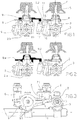
- Figure 1 shows a frontal view, according to an embodiment of the present invention, of two adjacent cocks, both manufactured according to the commonly-known technique with the only difference that, on the first cock there is a spark ignition microswitch manufactured, mounted and activated according to the commonly-known technique, while the second cock does not have a microswitch but an additional mechanical element which can activate the microswitch of the first cock.
- Figure 2 shows a further frontal view, substantially the same elements of the previous figure with only one variation relating to the additional mechanical element according to the present invention.
- Figure 3 shows a top view of the same elements of figure 1 as well as the so-called 'ramp', i.e. the tubing which supplies the gas cocks: the ramp is omitted in the previous figures for the sake of clarity.
- n o 1 denotes the gas ramp
- n o 2 denotes the body of a standard gas cock designed according to the commonly-known technique
- n o 2.b denotes a standard gas cock which can even be identical to the cock 2 except that it is fitted with an additional element according to the invention
- n o 3 denotes the cylindrical flange by means of which either gas cock 2 or 2 .b can be coupled to the ramp 1
- n o 4 denotes any of the knobs for gas cocks 2 or 2.b
- n o 5 denotes the shaft of a knob 4
- n o 6 denotes the body of a solenoid valve
- n o 6.1 denotes the feeler pin of the solenoid valve 6 whose pressure enables the opening of the solenoid valve 6 itself
- n o 7 denotes a microswitch mounted on a cock 2
- n o 7.1 denotes the feel
- the microswitch 7 is non incorporated in the cock 2 but simply mounted on this latter. If the knob 4 is pressed, the shaft 5 moves downwards and the striking element 8, mounted on to the shaft 5, crushes both the feeler pin 6.1 of the solenoid valve, opening it, and also the feeler pin 7.1 of the microswitch 7, if present.
- the said striking element 9 makes it possible not to mount a microswitch 7 on either of the cocks 2.b adjacent to a cock 2.
- the striking element 9 can be manufactured using any commonly-known material and technology and so it is not necessary to describe them.
- a preferred embodiment envisages moulded plastic, of a suitable mechanical and thermal resistance, fitted with hooking teeth 9.1 with which the striking element 8 can be locked in place.
- the said striking element 9 has a seating for coupling with the striking element 8 formed in such a way as to ensure the correct positioning of the first element with the second element, as the non-symmetrical positions of the teeth 9.1 show in the example in Fig. 3.
- a striking element 9.a is envisaged comprising the striking element 8 with the end 9.2 added.
- the material used will be the same as the material currently used to manufacture the striking elements 8. It could be advantageous, for production simplicity, to fit all the cocks 2 and 2.b., whether they are fitted with the microswitch 7 or not, with the same striking element 9 whose end 9.2, at the most, will not be used.
- the present invention has been described applied to gas cocks designed to be installed in cooking equipment fitted with a horizontal panel, but it is clear that, with elements and mechanical means equivalent to those described, this could also be applied to many other household gas cooking equipment in which optional ignition microswitches are mounted on the cocks and they are accessible, for activation, from the outside of the body of the said cocks.
- the said microswitch 7 mounted on a cock 2 cannot be accessed easily, because of its shape or position, by the striking elements 9 or 9.a mounted on a cock 2 .b, then the said microswitch 7 can be positioned between the two cocks 2.b, each one fitted with a striking element 9 or 9.a with the ends 9.2. in the appropriate positions, which can be identical if necessary.
Landscapes
- Engineering & Computer Science (AREA)
- Chemical & Material Sciences (AREA)
- Combustion & Propulsion (AREA)
- Mechanical Engineering (AREA)
- General Engineering & Computer Science (AREA)
- Feeding And Controlling Fuel (AREA)
- Mounting, Exchange, And Manufacturing Of Dies (AREA)
- Push-Button Switches (AREA)
Abstract
Description
- The invention relates to a device capable of reducing the number of microswitches usually used for the spark ignition of the gas burners of household cooking equipment.
- It is usual, in household cooking equipment fitted with gas burners, for the ignition of the burners to be effected by means of a spark created by a special igniter plug located near each of the burners: for wiring simplicity, a single electric circuit connects all the igniter plugs in parallel so that, when the circuit is closed, all the igniter plugs produce sparks, regardless of which burner needs to be ignited.
- To close this circuit there may be a special ignition button which comes into contact with the microswitches in series with the ignition plugs: this is located on the panel of the cooking equipment, independently of the knobs for the cocks, and the ignition is achieved by this being pushed down while the burner cock is opened at the same time.
- For the user's convenience and to limit the risk that, through carelessness, unconsumed gas is allowed to leak out, it is common to use cocks equipped with a microswitch. The microswitches are connected in parallel in the single electrical circuit which supplies all the igniter plugs. When the knob of the cock for the burner needed to be ignited is pressed, the relative solenoid valve to the burner opens while the microswitch, necessarily closes and, as in the case of a single button separate from the cocks, produces a spark from all the igniter plugs.
- Since the gas cut-off cock is a due and compulsory safety component, usually incorporated in the cock, while the spark ignition is an optional function, the microswitch is a separate element which can be mounted on the cock adapted to receive it.
- With the presence of a microswitch on each of the cocks the ignition manoeuvre is more convenient and safer, as the user simply has to press the knob down to ignite the burner, but it has the drawback of an additional cost since a microswitch must be provided for each gas cock.
- The present invention, in the case of household cooking equipment fitted with at least two gas burners supplied by means of corresponding cocks mounted next to each other and fitted with a spark ignition activated by means of microswitches attached to the said cocks, aims to allow the removal of one microswitch from each pair of adjacent cocks.
- A further aim of the present invention is to achieve this objective by simply applying an additional mechanical element to the standard cocks manufactured according to the commonly-known technique.
- These aims are achieved through a device according to the present invention in which the ignition spark is produced, for at least one cock because the said cock is equipped with a striking element which comes into contact with the microswitch mounted either on a second cock or close to this latter or positioned between the two and, however, in such a way that the said microswitch can be activated by both the first and the second cock, each one independently of the other.
- The characteristics of the device according to the present invention will better emerge from the detailed description of some preferred but not exclusive embodiments that follows, with reference to the accompanying drawings, provided in the form of a non-limiting example which shows the gas cock with a vertical knob shaft, of a type designed to be mounted on a cooking hob or, in any case, on a horizontal surface.
- Figure 1 shows a frontal view, according to an embodiment of the present invention, of two adjacent cocks, both manufactured according to the commonly-known technique with the only difference that, on the first cock there is a spark ignition microswitch manufactured, mounted and activated according to the commonly-known technique, while the second cock does not have a microswitch but an additional mechanical element which can activate the microswitch of the first cock.
- Figure 2 shows a further frontal view, substantially the same elements of the previous figure with only one variation relating to the additional mechanical element according to the present invention.
- Figure 3 shows a top view of the same elements of figure 1 as well as the so-called 'ramp', i.e. the tubing which supplies the gas cocks: the ramp is omitted in the previous figures for the sake of clarity.
- In the three figures the most important elements are highlighted with identification numbers, to be exact:
n o 1 denotes the gas ramp;n o2 denotes the body of a standard gas cock designed according to the commonly-known technique; no2.b denotes a standard gas cock which can even be identical to thecock 2 except that it is fitted with an additional element according to the invention;n o3 denotes the cylindrical flange by means of which eithergas cock ramp 1; no4 denotes any of the knobs forgas cocks 2 or 2.b;n o 5 denotes the shaft of a knob 4;n o6 denotes the body of a solenoid valve; no 6.1 denotes the feeler pin of thesolenoid valve 6 whose pressure enables the opening of thesolenoid valve 6 itselfn o7 denotes a microswitch mounted on acock 2; no 7.1 denotes the feeler pin of themicroswitch 7;n o8 denotes the striking element according to the commonly-known technique mounted onto theshaft 5 of acock 2 which can be pressed at the same time as the feeler pins 6.1 and 7.1 of, respectively, thesolenoid valve 6 and themicroswitch 7;n o 9 denotes an additional striking element according to the invention mounted on the cock 2.b; no 9.1 denotes the teeth for hooking the additionalstriking element 9 to thestriking element 8; no 9.a denotes a second possible embodiment of the additional striking element according to the invention, mounted on the cock 2.b; no9.2 denotes one end of the said additionalstriking elements 9 or 9.a. - The functioning modes and the advantages of the invention have already been highlighted by the description of the figures.
- According to the current technique, to cause the ignition of the burners by means of a spark, it is preferred not to use a separate button but to attach a
microswitch 7 to each of thecocks 2, naturally only if the spark ignition, an optional extra, is envisaged. This is why themicroswitch 7 is non incorporated in thecock 2 but simply mounted on this latter. If the knob 4 is pressed, theshaft 5 moves downwards and thestriking element 8, mounted on to theshaft 5, crushes both the feeler pin 6.1 of the solenoid valve, opening it, and also the feeler pin 7.1 of themicroswitch 7, if present. - According to a first embodiment of the invention, and with reference to the figures 1 and 3, since a
cock 2 has already been envisaged, equipped with amicroswitch 7, it is possible to attach a cock 2.b. adjacent to the additionalstriking element 9. As the cock 2.b. opens, initiated by means of the pressure of the corresponding knob 4, thecorresponding solenoid valve 6 is opened while the additionalstriking element 9 presses, by means of the end 9.2, the feeler pin 7.1 of theadjacent cock 2 without, however, interfering with the similar operation which can be activated by thestriking element 8 of the saidcock 2 nor activating thesolenoid valve 6 of thesame cock 2. - The said
striking element 9 makes it possible not to mount amicroswitch 7 on either of the cocks 2.b adjacent to acock 2. - The
striking element 9 can be manufactured using any commonly-known material and technology and so it is not necessary to describe them. A preferred embodiment envisages moulded plastic, of a suitable mechanical and thermal resistance, fitted with hooking teeth 9.1 with which thestriking element 8 can be locked in place. Obviously the saidstriking element 9 has a seating for coupling with thestriking element 8 formed in such a way as to ensure the correct positioning of the first element with the second element, as the non-symmetrical positions of the teeth 9.1 show in the example in Fig. 3. - According to a further embodiment of the invention, in figure 2 a striking element 9.a is envisaged comprising the
striking element 8 with the end 9.2 added. In this case, preferably, the material used will be the same as the material currently used to manufacture thestriking elements 8. It could be advantageous, for production simplicity, to fit all thecocks 2 and 2.b., whether they are fitted with themicroswitch 7 or not, with the samestriking element 9 whose end 9.2, at the most, will not be used. - The present invention has been described applied to gas cocks designed to be installed in cooking equipment fitted with a horizontal panel, but it is clear that, with elements and mechanical means equivalent to those described, this could also be applied to many other household gas cooking equipment in which optional ignition microswitches are mounted on the cocks and they are accessible, for activation, from the outside of the body of the said cocks.
- If the said
microswitch 7, mounted on acock 2, cannot be accessed easily, because of its shape or position, by thestriking elements 9 or 9.a mounted on acock 2 .b, then the saidmicroswitch 7 can be positioned between the two cocks 2.b, each one fitted with astriking element 9 or 9.a with the ends 9.2. in the appropriate positions, which can be identical if necessary. - An advantage of the invention just described is clear: by means of the application of an additional
striking element 9 or by means of a striking element 9.a produced by modifying slightly a standardstriking element 8, it is possible, for each pair of adjacent cocks, to remove one ignition microswitch and the relative wiring without it being necessary to modify any other component of the cooking equipment in any way.
Claims (8)
- Household cooking equipment fitted with at least two gas burners supplied by means of corresponding cocks (2, 2b) mounted next to each other and equipped with a spark ignition activated by means of the closing of one or more microswitches (7) attached to the said cocks (2, 2b) characterised by the fact that at least one cock (2, 2.b) is fitted with a striking element (9, 9.a) which comes into contact, by means of an end (9.2), with the feeler pin (7.1) of a microswitch (7) mounted on a second cock (2) adjacent to the first cock (2.b), said microswitch (7) being activated independently of both the first and the second cock (2, 2.b).
- Household cooking equipment fitted with at least two gas burners supplied by means of corresponding cocks (2, 2b) mounted next to each other and equipped with a spark ignition activated by means of the closing of one or more microswitches (7) attached to the said cocks (2, 2b) characterised by the fact that both cocks (2.b) are fitted with a striking element (9,9.a) which comes into contact, by means of one end (9.2), with the feeler pin (7.1) of a microswitch (7) positioned between the said cocks (2.b), said microswitches being activated independently of both the first and second cock (2.b).
- Household cooking equipment according to claims 1 or 2 characterised by the fact that the striking element (9) is an additional element which can be applied to a cock (2.b) which does not have a microswitch (7).
- Household cooking equipment according to claim 3 characterised by the fact that the striking element (9) can be attached to a striking element (8) of a cock (2 .b) which does not have a microswitch (7) using commonly-known means such as hooking teeth (9.1) or other commonly-known means capable of guaranteeing the correct positioning.
- Household cooking equipment according to claim 4 characterised by the fact that the striking element (9) can be manufactured using any suitable material such as moulded plastic with sufficient thermal and mechanical resistance.
- Household cooking equipment according to claims 1 or 2 characterised by the fact that the striking element (9.a) is created from a striking element (8) according to the commonly-known technique with an end (9.2) added to it.
- Household cooking equipment according to claim 6 characterised by the fact that all the cocks (2.b) are fitted with striking elements (9.a) whether the end (9.2) is necessary or not.
- Gas cocks for household cooking equipment having one or more of the characteristics listed in the individual claims above.
Applications Claiming Priority (2)
| Application Number | Priority Date | Filing Date | Title |
|---|---|---|---|
| ITAN990011U | 1999-03-08 | ||
| IT99AN000011 IT248927Y1 (en) | 1999-03-08 | 1999-03-08 | DOMESTIC GAS COOKING APPLIANCES WITH SIMPLIFIED SPARK IGNITION DEVICE |
Publications (3)
| Publication Number | Publication Date |
|---|---|
| EP1035378A2 true EP1035378A2 (en) | 2000-09-13 |
| EP1035378A3 EP1035378A3 (en) | 2001-04-25 |
| EP1035378B1 EP1035378B1 (en) | 2006-06-28 |
Family
ID=11334295
Family Applications (1)
| Application Number | Title | Priority Date | Filing Date |
|---|---|---|---|
| EP20000103200 Expired - Lifetime EP1035378B1 (en) | 1999-03-08 | 2000-02-17 | Household gas cooking equipment with a simplified spark ignition device |
Country Status (4)
| Country | Link |
|---|---|
| EP (1) | EP1035378B1 (en) |
| DE (1) | DE60029037T2 (en) |
| ES (1) | ES2267423T3 (en) |
| IT (1) | IT248927Y1 (en) |
Cited By (2)
| Publication number | Priority date | Publication date | Assignee | Title |
|---|---|---|---|---|
| EP1500881A3 (en) * | 2003-07-25 | 2005-06-15 | ITW Industrial Components S.r.l. | Integrated device for gas-cooking hobs including a gas tap and an ignitor |
| EP2390575A3 (en) * | 2010-05-24 | 2013-01-09 | BSH Bosch und Siemens Hausgeräte GmbH | Gas valve with an actuating device for an electric switch |
Family Cites Families (3)
| Publication number | Priority date | Publication date | Assignee | Title |
|---|---|---|---|---|
| DE1429108C3 (en) * | 1963-02-06 | 1978-04-06 | Imperial-Werke Gmbh, 4980 Buende | High-voltage ignition device for gas burners on gas stoves and the like |
| DE1905797A1 (en) * | 1969-02-06 | 1970-10-01 | Junkers & Co | Gas stove with several burners and a piezoelectric ignition device |
| FR2708087B1 (en) * | 1993-07-23 | 1995-09-01 | Cepem | Integrated ignition device for gas appliance. |
-
1999
- 1999-03-08 IT IT99AN000011 patent/IT248927Y1/en active
-
2000
- 2000-02-17 DE DE2000629037 patent/DE60029037T2/en not_active Expired - Fee Related
- 2000-02-17 EP EP20000103200 patent/EP1035378B1/en not_active Expired - Lifetime
- 2000-02-17 ES ES00103200T patent/ES2267423T3/en not_active Expired - Lifetime
Non-Patent Citations (1)
| Title |
|---|
| None |
Cited By (3)
| Publication number | Priority date | Publication date | Assignee | Title |
|---|---|---|---|---|
| EP1500881A3 (en) * | 2003-07-25 | 2005-06-15 | ITW Industrial Components S.r.l. | Integrated device for gas-cooking hobs including a gas tap and an ignitor |
| US7243647B2 (en) | 2003-07-25 | 2007-07-17 | Itw Industrial Components S.R.L. | Universal integrated device for controlling gas-burner rings of a cooking surface including a gas tap and a catenary element |
| EP2390575A3 (en) * | 2010-05-24 | 2013-01-09 | BSH Bosch und Siemens Hausgeräte GmbH | Gas valve with an actuating device for an electric switch |
Also Published As
| Publication number | Publication date |
|---|---|
| EP1035378A3 (en) | 2001-04-25 |
| ES2267423T3 (en) | 2007-03-16 |
| DE60029037D1 (en) | 2006-08-10 |
| ITAN990011U1 (en) | 1999-06-08 |
| IT248927Y1 (en) | 2003-03-06 |
| DE60029037T2 (en) | 2007-01-11 |
| EP1035378B1 (en) | 2006-06-28 |
Similar Documents
| Publication | Publication Date | Title |
|---|---|---|
| US6375150B1 (en) | Knob for gas apparatus with safety button | |
| EP3175176B1 (en) | Flame ignition control device for burners or the like | |
| EP1194720B1 (en) | An electrical switch for gas cocks | |
| EP1207348A1 (en) | A lighter with a lock-off switch | |
| CA2354608C (en) | Safety electronic lighter | |
| EP1035378B1 (en) | Household gas cooking equipment with a simplified spark ignition device | |
| CN101213405B (en) | Flame ignition device for gas burners | |
| EP3077730A1 (en) | Gas cooking appliance | |
| GB2252618A (en) | Igniting a gas burner of a simmering and cooking equipment | |
| US11353216B2 (en) | Switch assembly | |
| DE4238816C1 (en) | Gas stove with a ceramic hob | |
| GB1488137A (en) | Piezoelectric lighters for domestic appliances burners | |
| GB2189578A (en) | Gas tap assembly | |
| JPS6040568B2 (en) | Gas combustion safety device | |
| KR910000557Y1 (en) | Pressure-cooker | |
| ES2142220A1 (en) | Igniter controller for gas cooker burner | |
| ES2383612T3 (en) | Cooking device | |
| KR19990001691A (en) | Switch structure of oven burner igniter | |
| JPH087238Y2 (en) | Reset device for gas shut-off emergency shutoff valve with built-in cylinder | |
| KR200257762Y1 (en) | Valve for exhausting steam from rice cooker | |
| KR910001220Y1 (en) | Gas pressure cooker | |
| KR920005748Y1 (en) | Ignition device for gas range | |
| KR900008319Y1 (en) | Burner device in gas equipment | |
| ES2258911A1 (en) | Gas cooking plate | |
| KR100377724B1 (en) | Power supply device for ventillation hooded microwave oven |
Legal Events
| Date | Code | Title | Description |
|---|---|---|---|
| PUAI | Public reference made under article 153(3) epc to a published international application that has entered the european phase |
Free format text: ORIGINAL CODE: 0009012 |
|
| AK | Designated contracting states |
Kind code of ref document: A2 Designated state(s): DE ES FR GB |
|
| AX | Request for extension of the european patent |
Free format text: AL;LT;LV;MK;RO;SI |
|
| PUAL | Search report despatched |
Free format text: ORIGINAL CODE: 0009013 |
|
| AK | Designated contracting states |
Kind code of ref document: A3 Designated state(s): AT BE CH CY DE DK ES FI FR GB GR IE IT LI LU MC NL PT SE |
|
| AX | Request for extension of the european patent |
Free format text: AL;LT;LV;MK;RO;SI |
|
| 17P | Request for examination filed |
Effective date: 20010305 |
|
| AKX | Designation fees paid |
Free format text: DE ES FR GB |
|
| 17Q | First examination report despatched |
Effective date: 20040414 |
|
| RAP1 | Party data changed (applicant data changed or rights of an application transferred) |
Owner name: INDESIT COMPANY S.P.A. |
|
| GRAP | Despatch of communication of intention to grant a patent |
Free format text: ORIGINAL CODE: EPIDOSNIGR1 |
|
| GRAS | Grant fee paid |
Free format text: ORIGINAL CODE: EPIDOSNIGR3 |
|
| GRAA | (expected) grant |
Free format text: ORIGINAL CODE: 0009210 |
|
| AK | Designated contracting states |
Kind code of ref document: B1 Designated state(s): DE ES FR GB |
|
| REG | Reference to a national code |
Ref country code: GB Ref legal event code: FG4D |
|
| REF | Corresponds to: |
Ref document number: 60029037 Country of ref document: DE Date of ref document: 20060810 Kind code of ref document: P |
|
| ET | Fr: translation filed | ||
| REG | Reference to a national code |
Ref country code: ES Ref legal event code: FG2A Ref document number: 2267423 Country of ref document: ES Kind code of ref document: T3 |
|
| PLBE | No opposition filed within time limit |
Free format text: ORIGINAL CODE: 0009261 |
|
| STAA | Information on the status of an ep patent application or granted ep patent |
Free format text: STATUS: NO OPPOSITION FILED WITHIN TIME LIMIT |
|
| 26N | No opposition filed |
Effective date: 20070329 |
|
| PGFP | Annual fee paid to national office [announced via postgrant information from national office to epo] |
Ref country code: DE Payment date: 20090331 Year of fee payment: 10 |
|
| PG25 | Lapsed in a contracting state [announced via postgrant information from national office to epo] |
Ref country code: DE Free format text: LAPSE BECAUSE OF NON-PAYMENT OF DUE FEES Effective date: 20100901 |
|
| PGFP | Annual fee paid to national office [announced via postgrant information from national office to epo] |
Ref country code: ES Payment date: 20110223 Year of fee payment: 12 Ref country code: GB Payment date: 20110216 Year of fee payment: 12 |
|
| PGFP | Annual fee paid to national office [announced via postgrant information from national office to epo] |
Ref country code: FR Payment date: 20120316 Year of fee payment: 13 |
|
| GBPC | Gb: european patent ceased through non-payment of renewal fee |
Effective date: 20120217 |
|
| PG25 | Lapsed in a contracting state [announced via postgrant information from national office to epo] |
Ref country code: GB Free format text: LAPSE BECAUSE OF NON-PAYMENT OF DUE FEES Effective date: 20120217 |
|
| REG | Reference to a national code |
Ref country code: ES Ref legal event code: FD2A Effective date: 20130709 |
|
| PG25 | Lapsed in a contracting state [announced via postgrant information from national office to epo] |
Ref country code: ES Free format text: LAPSE BECAUSE OF NON-PAYMENT OF DUE FEES Effective date: 20120218 |
|
| REG | Reference to a national code |
Ref country code: FR Ref legal event code: ST Effective date: 20131031 |
|
| PG25 | Lapsed in a contracting state [announced via postgrant information from national office to epo] |
Ref country code: FR Free format text: LAPSE BECAUSE OF NON-PAYMENT OF DUE FEES Effective date: 20130228 |