EP1034923A1 - Vorrichtung zur Vermeidung von Zahnradspiel in Getrieben - Google Patents
Vorrichtung zur Vermeidung von Zahnradspiel in Getrieben Download PDFInfo
- Publication number
- EP1034923A1 EP1034923A1 EP00103433A EP00103433A EP1034923A1 EP 1034923 A1 EP1034923 A1 EP 1034923A1 EP 00103433 A EP00103433 A EP 00103433A EP 00103433 A EP00103433 A EP 00103433A EP 1034923 A1 EP1034923 A1 EP 1034923A1
- Authority
- EP
- European Patent Office
- Prior art keywords
- gear
- drive gear
- bores
- ring
- drive
- Prior art date
- Legal status (The legal status is an assumption and is not a legal conclusion. Google has not performed a legal analysis and makes no representation as to the accuracy of the status listed.)
- Granted
Links
- 238000007639 printing Methods 0.000 claims description 5
- 230000033001 locomotion Effects 0.000 claims description 4
- 238000007645 offset printing Methods 0.000 claims 1
- 238000006073 displacement reaction Methods 0.000 description 3
- 238000005452 bending Methods 0.000 description 2
- 238000003780 insertion Methods 0.000 description 2
- 230000037431 insertion Effects 0.000 description 2
- 238000004519 manufacturing process Methods 0.000 description 2
- 230000001133 acceleration Effects 0.000 description 1
- 230000005540 biological transmission Effects 0.000 description 1
- 238000005553 drilling Methods 0.000 description 1
- 230000036316 preload Effects 0.000 description 1
- 230000003068 static effect Effects 0.000 description 1
- 230000007704 transition Effects 0.000 description 1
Images


Classifications
-
- F—MECHANICAL ENGINEERING; LIGHTING; HEATING; WEAPONS; BLASTING
- F16—ENGINEERING ELEMENTS AND UNITS; GENERAL MEASURES FOR PRODUCING AND MAINTAINING EFFECTIVE FUNCTIONING OF MACHINES OR INSTALLATIONS; THERMAL INSULATION IN GENERAL
- F16H—GEARING
- F16H55/00—Elements with teeth or friction surfaces for conveying motion; Worms, pulleys or sheaves for gearing mechanisms
- F16H55/02—Toothed members; Worms
- F16H55/17—Toothed wheels
- F16H55/18—Special devices for taking up backlash
-
- B—PERFORMING OPERATIONS; TRANSPORTING
- B41—PRINTING; LINING MACHINES; TYPEWRITERS; STAMPS
- B41F—PRINTING MACHINES OR PRESSES
- B41F13/00—Common details of rotary presses or machines
- B41F13/008—Mechanical features of drives, e.g. gears, clutches
- B41F13/012—Taking-up backlash
-
- Y—GENERAL TAGGING OF NEW TECHNOLOGICAL DEVELOPMENTS; GENERAL TAGGING OF CROSS-SECTIONAL TECHNOLOGIES SPANNING OVER SEVERAL SECTIONS OF THE IPC; TECHNICAL SUBJECTS COVERED BY FORMER USPC CROSS-REFERENCE ART COLLECTIONS [XRACs] AND DIGESTS
- Y10—TECHNICAL SUBJECTS COVERED BY FORMER USPC
- Y10T—TECHNICAL SUBJECTS COVERED BY FORMER US CLASSIFICATION
- Y10T74/00—Machine element or mechanism
- Y10T74/19—Gearing
- Y10T74/19623—Backlash take-up
-
- Y—GENERAL TAGGING OF NEW TECHNOLOGICAL DEVELOPMENTS; GENERAL TAGGING OF CROSS-SECTIONAL TECHNOLOGIES SPANNING OVER SEVERAL SECTIONS OF THE IPC; TECHNICAL SUBJECTS COVERED BY FORMER USPC CROSS-REFERENCE ART COLLECTIONS [XRACs] AND DIGESTS
- Y10—TECHNICAL SUBJECTS COVERED BY FORMER USPC
- Y10T—TECHNICAL SUBJECTS COVERED BY FORMER US CLASSIFICATION
- Y10T74/00—Machine element or mechanism
- Y10T74/19—Gearing
- Y10T74/1987—Rotary bodies
- Y10T74/19893—Sectional
- Y10T74/19898—Backlash take-up
Definitions
- the invention relates to a device for avoiding gear play in transmissions in particular in gearboxes of web-fed rotary printing machines, according to the preamble of claim 1.
- the high-performance drive motors used in printing presses require gears, which transmit both acceleration torques and braking torques can, without the normal game between the Gear wheels of the gearbox causing a position error, with a very high Speed rotating gears tilt the meshing teeth a first gear and an associated second gear, e.g. B. one Drive gear and an output gear, to each other in the circumferential direction to separate, and when changing the torque, d. H. with a load change on Drive gear, arise due to the inertia of the gear driven components problems due to the backlash of the gears is due.
- US 5,813,335 describes a device for preventing play in which a Drive gear and an additional gear are provided.
- the additional Gear generally also referred to below as the output gear, is a recess formed in which a leaf spring arrangement is received, which the teeth of the additional gear so that it avoids play with respect to the teeth of the driven gear opposite to the drive gear turns.
- the additional gear must be of minimal size (minimal Diameter) to accommodate the leaf spring arrangement.
- the length of the Leaf springs for generating the play compensation forces is also low, so that the Leaf springs have an undesirably high spring constant. Because of the complex This arrangement is also very cost-intensive in terms of precision requirements Manufacturing.
- the device according to the invention for avoiding gear play includes a rotationally fixed drive gear disposed on a drive shaft with a plurality of therein through holes formed, which is in mesh with an output gear, to drive this without play.
- the device further comprises one on the Drive gear attached to rod ring, an idler gear with a variety of therein formed, corresponding to the through holes of the drive gear Through holes, a power ring attached to the enclosed gear with a Variety of receiving bores formed therein, and spring-loaded or overhung torsionally elastic rods, which are attached at one end to the rod ring and through which Numerous through holes in the drive gear and the adjacent gear to the mounting holes, and that the enclosed gear and the Preload drive gear in opposite directions.
- Another feature of the invention is that the plurality of Through holes in the drive gear and in the accompanying gear and the A plurality of receiving bores are preferably each offset from one another are.
- the resilient rods preferably run through the large number of through holes in the drive gear and the accompanying gear, without the respective gear too touch.
- the accompanying gearwheel preferably has a hub on which the force ring is attached.
- the resilient rods can also be designed as overhung resilient rods, which run through the through holes into the force ring and along their length is curved so that the force to bias the idler gear and the drive gear in opposite directions.
- the scope of the force ring has preferably a notch, which can accommodate a hexagon wrench, by means of of which the power ring can be turned.
- the accompanying gear is coaxial with the drive gear and adjacent to it on the drive shaft and freely rotatable around the drive shaft.
- a bore can also be formed in the drive gear, in which a bushing can be included.
- the bushing preferably has a conical, stepped inner bore.
- To the accompanying gear can also be formed a threaded bore that a Includes threaded pin, one end of the conical, stepped inner bore of the Bush is shaped accordingly and the other end has a thread and in the Threaded bore is arranged.
- the threaded pin interacts with the socket and is used in a first position on the one hand to lock the toothed gear with the Align drive gear and in a second position on the other hand, the Limit movement of the idler gear with respect to the drive gear.
- the force ring also preferably has a bore which is connected to the threaded bore of the accompanying gear can be aligned so that the arranged in the threaded hole Pin is accessible.
- FIG. 1 shows an exploded perspective view of a device according to the invention to avoid gear play, which a drive gear 1 with teeth 1 'and a includes spur gear 2 with teeth 2 '.
- the attached gear 2 causes one Torque component to avoid gear play.
- the drive gear 1 and the accompanying gear 2 are preferably adjacent to each other in such a way common shaft are arranged so that they together in a third, not shown Gear wheel which is wide enough to coaxially in the teeth 1, 2 'of both arranged gears 1, 2 to engage, and which subsequently also as Output gear is called.
- the teeth 1 'of the drive gear 1 press against one Side of the teeth of the third gear, while the teeth 2 'of the secondary gear 2 press against the other side of the output gear teeth.
- the drive gear 1 is rotatably and the accompanying gear 2 is rotatably arranged on the common shaft.
- a rod ring 4 On one side of the drive gear 1, a rod ring 4 is provided, which by means of Collar pin 9 is held exactly in position on the drive gear 1.
- a variety of cantilevered resilient or resilient Rods 8 attached, which extends from the rod ring 4 in the in the drive gear 1 and the through gear 2 formed through holes 13 and 17 extend.
- the Resilient rods 8 preferably run through the through bores without contact 13, 17 and serve as a cantilever support or cantilever spring for generating a Torque to avoid gear play between the drive gear 1 and Output gear.
- the through holes 13, 17 in the gears 1, 2 are in Direction of rotation offset and thus allow the resilient rods to bend 8.
- a rotatable force ring 3 is arranged, the Rotational position by means of a in the power ring 3 and a hole in the enclosed Gear 2 insertable positioning pin 10 is fixed.
- the power ring 3 we also from two Screws 11 held in position on the accompanying gear 2.
- the power ring 3 also has a variety of offset in the direction of rotation Through holes 17 of the adjacent gear 2 corresponding receiving holes 14, which preferably the ends of the toothed gear 2 emerging spring rods 8 take up.
- the force ring 3 is in a way on the attached gear 2 that the position of the mounting holes 14 a a boom comparable bending of the resilient rods 8 causes when this in the Receiving holes 14 are inserted.
- the bending plane of the overhung resilient rods 8 run perpendicular to the radial of the gear arrangement.
- the bend generates a torque between the adjacent gears 1, 2, which through a circular arrangement of a plurality of resilient rods 8 each desired value can be increased.
- the resilient rods 8 produce a between the coaxially arranged gears 1, 2 Torsional force.
- the gears 1, 2 exercise an identical, but oppositely directed contact force on the teeth of the driven gear, not shown off, so that no drive force acts on the output gear.
- the contact force of the Teeth of the non-rotatably arranged drive gear 1 is increased.
- a opposite torque becomes the contact force of the teeth of the drive gear 1 reduced, but remains greater than zero due to the spring force of the resilient rods 8, limited by the spring force of the resilient rods 8.
- a hardened bushing 7 and a pin 6 are provided.
- the hardened bushing 7 is inserted into a counter bore formed in the side of the drive gear 1 and has a conical insertion surface 15, the shape of which corresponds to the associated end of the pin 6 corresponds to a transition between the alignment function and the function of the To limit the mutual displacement of the teeth 1 ', 2'.
- the pin 6 is arranged in a threaded bore 19 in the adjacent gear 2. The movement of the pin 6 away from the hardened bushing 7 is preferably by the force ring 3rd limited.
- a bore 20 is provided in the force ring 3 which is large enough to to allow access to a hexagon head of the pin 6, but smaller than the diameter of the pin 6 is.
- the position of the pin 6 can the bore 20 in the force ring 3 by means of a hexagon wrench by simple Turning the pin 6 in and out can be adjusted.
- This allows the position of the Pin 6 can be adjusted in a suitable manner to a desired displacement enable so that the pin 6 can perform its double function.
- the force ring 3 preferably has a notch 16 or another recess in which is a tool, e.g. B. can intervene a hex key, by means of which Force ring 3 can be rotated.
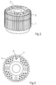
- Fig. 2 shows a perspective view of the device for Avoidance of gear play when assembled.
- FIG. 3 shows a front view of the assembled device from the force ring 3 considered.
- Fig. 4 shows a side view of the device according to the invention in assembled Condition
- Fig. 5 shows a rear view of the assembled device of the on a drive shaft 21 attached rod ring 4 viewed from.
- Another area of application of the present invention is e.g. B. smooth running Drive devices.
- the low spring constant combined with a comparatively high one driven mass causes a low natural frequency, such as that used to dampen Drive problems is desirable.
Landscapes
- Engineering & Computer Science (AREA)
- Mechanical Engineering (AREA)
- General Engineering & Computer Science (AREA)
- Gears, Cams (AREA)
- Arrangement And Mounting Of Devices That Control Transmission Of Motive Force (AREA)
- Structure Of Transmissions (AREA)
Abstract
Description
- Fig. 1
- eine schematische, perspektivische Explosionsansicht einer erfindungsgemäßen Vorrichtung zur Vermeidung von Spiel;
- Fig. 2
- eine perspektivische Draufsicht auf eine zusammengebaute erfindungsgemäße Vorrichtung;
- Fig. 3
- eine Vorderansicht der erfindungsgemäßen Vorrichtung;
- Fig. 4
- eine Seitenansicht der erfindungsgemäßen Vorrichtung; und
- Fig. 5
- eine Rückansicht der erfindungsgemäßen Vorrichtung.
- 1
- Antriebszahnrad
- 1'
- Zähne
- 2
- beilaufendes Zahnrad
- 2'
- Zähne
- 3
- Kraftring
- 4
- Stabring
- 6
- Zapfen
- 7
- gehärtete Buchse
- 8
- federnde Stäbe
- 9
- Bundbolzen
- 10
- Positionierzapfen
- 12
- Nabe
- 13
- Durchsteckbohrungen
- 14
- Aufnahmebohrungen
- 15
- konische Einfügefläche
- 16
- Kerbe
- 17
- Durchsteckbohrungen
- 18
- Gegenbohrung
- 20
- Bohrung
- 21
- Antriebswelle
Claims (10)
- Vorrichtung zur Vermeidung von Zahnradspiel zwischen einem Antriebszahnrad (1) und einem Abtriebszahnrad, insbesondere zum Antrieb von Druckmaschinenzylindern in einer Rollenrotations-Offsetdruckmaschine,
gekennzeichnet durch
eine Vielzahl von im Antriebszahnrad (1) gebildeten Drucksteckbohrungen (13), einem am Antriebszahnrad (1) befestigten Stabring (4), einem beilaufenden Zahnrad (2) mit einer Vielzahl von darin gebildeten, den Durchsteckbohrungen (13) des Antriebszahnrades (1) zugeordneten Durchsteckbohrungen (17), einen mit dem beilaufenden Zahnrad (2) verbundenen Kraftring (3) mit einer Vielzahl von darin angeordneten Aufnahmebohrungen (14); sowie federelastischen Elementen (8), welche mit ihrem einen Ende am Stabring (4) befestigt sind und welche sich durch die Vielzahl von Durchsteckbohrungen (13, 17) im Antriebszahnrad (1) sowie im beilaufenden Zahnrad (2) hindurch bis zu den Aufnahmenbohrungen (14) des Kraftrings (3) erstrecken und eine Kraft ausüben, durch die das beilaufende Zahnrad (2) und das Antriebszahnrad (1) in entgegengesetzten Richtungen vorspannbar ist. - Vorrichtung nach Anspruch 1,
dadurch gekennzeichnet,
dass die Vielzahl von Durchsteckbohrungen (13, 17) im Antriebszahnrad (1) und im beilaufenden Zahnrad (2) und die Vielzahl von Aufnahmebohrungen (14) im Kraftring (3) in Drehrichtung der Zahnräder betrachtet zueinander versetzt angeordnet sind. - Vorrichtung nach Anspruch 2,
dadurch gekennzeichnet,
dass die federelastischen Elemente (8) berührungsfrei durch die Durchsteckbohrungen (13, 17) im Antriebszahnrad (1) und im beilaufenden Zahnrad (2) verlaufen. - Vorrichtung nach einem der vorhergehenden Ansprüche,
dadurch gekennzeichnet,
dass zur Befestigung des Kraftrings (4) eine Nabe (12) am beilaufenden Zahnrad (2) vorgesehen ist. - Vorrichtung nach einem der vorhergehenden Ansprüche,
dadurch gekennzeichnet,
dass die federelastischen Elemente (8) als federelastische Stäbe ausgebildet sind, welche vergleichbar mit einem Ausleger in ihrem Verlauf von dem Stabring (4) zu dem Kraftring (3) gebogen werden, so dass sie eine Kraft ausüben, durch welche das beilaufende Zahnrad (2) und das Antriebszahnrad (1) in entgegengesetzten Richtungen zueinander vorspannbar sind. - Vorrichtung nach einem der vorhergehenden Ansprüche,
dadurch gekennzeichnet,
dass am Umfang des Kraftring (3) eine Kerbe (16) ausgebildet ist, in die zum Drehen des Kraftrings (3) ein Werkzeug eingreifen kann. - Vorrichtung nach einem der vorhergehenden Ansprüche,
dadurch gekennzeichnet,
dass das beilaufende Zahnrad (2) und das Antriebszahnrad (1) koaxial und aneinander angrenzend auf einer Antriebswelle (21) montierbar sind und dass das beilaufende Zahnrad (2) um die Antriebswelle (21) frei drehbar ist. - Vorrichtung nach einem der vorhergehenden Ansprüche,
dadurch gekennzeichnet,
dass im Antriebszahnrad (1) eine Bohrung gebildet ist, und dass das Antriebszahnrad (1) eine in der Bohrung angeordnete Buchse (7) umfasst. - Vorrichtung nach Anspruch 8,
dadurch gekennzeichnet,
dass die Buchse (7) eine konische, gestufte Innenbohrung aufweist, dass im beilaufenden Zahnrad (2) eine Gewindebohrung (19) gebildet ist, und dass ein Gewindezapfen (6) vorgesehen ist, welcher ein entsprechend der konischen, gestuften Innenbohrung der Buchse (7) geformtes Ende und ein in der Gewindebohrung (19) angeordnetes Gewindeende aufweist und welcher mit der Buchse (7) derart zusammenwirkt, dass das beilaufende Zahnrad (2) mit dem Antriebszahnrad (1) ausrichtbar und eine Bewegung des beilaufenden Zahnrads (2) bezüglich des Antriebszahnrads (1) begrenzbar ist. - Vorrichtung nach Anspruch 9,
dadurch gekennzeichnet,
dass im Kraftring (4) eine Bohrung vorgesehen ist, welche mit der Gewindebohrung (19) des beilaufenden Zahnrads (2) in einer Weise ausrichtbar ist, dass der in der Gewindebohrung (19) angeordnete Zapfen (6) zugänglich ist.
Applications Claiming Priority (2)
| Application Number | Priority Date | Filing Date | Title |
|---|---|---|---|
| US09/265,621 US6148684A (en) | 1999-03-10 | 1999-03-10 | Anti-backlash gear |
| US265621 | 1999-03-10 |
Publications (2)
| Publication Number | Publication Date |
|---|---|
| EP1034923A1 true EP1034923A1 (de) | 2000-09-13 |
| EP1034923B1 EP1034923B1 (de) | 2002-09-04 |
Family
ID=23011218
Family Applications (1)
| Application Number | Title | Priority Date | Filing Date |
|---|---|---|---|
| EP00103433A Expired - Lifetime EP1034923B1 (de) | 1999-03-10 | 2000-02-25 | Vorrichtung zur Vermeidung von Zahnradspiel in Getrieben |
Country Status (5)
| Country | Link |
|---|---|
| US (1) | US6148684A (de) |
| EP (1) | EP1034923B1 (de) |
| JP (1) | JP4669102B2 (de) |
| AT (1) | ATE223309T1 (de) |
| DE (2) | DE50000432D1 (de) |
Cited By (4)
| Publication number | Priority date | Publication date | Assignee | Title |
|---|---|---|---|---|
| EP1536161A1 (de) | 2003-11-25 | 2005-06-01 | Bobst S.A. | Spielfreie Getriebeanordnung |
| WO2009106222A1 (de) * | 2008-02-26 | 2009-09-03 | Maxon Motor Ag | Spielfreies planetengetriebe mit geteilten planetenrädern, die durch parallel zur planetenrotationsachse angeordnete federstäbe vorgespannt sind |
| EP2006096A3 (de) * | 2007-06-01 | 2012-03-21 | manroland AG | Angetriebene Baugruppe einer Druckmaschine |
| EP2735767A1 (de) * | 2012-11-23 | 2014-05-28 | Maxon Motor AG | Verdrehspielfreies Planetengetriebe mit zueinander vorgespannten Planetenträgern |
Families Citing this family (31)
| Publication number | Priority date | Publication date | Assignee | Title |
|---|---|---|---|---|
| DE10226850B3 (de) * | 2002-06-15 | 2004-01-22 | Motorenfabrik Hatz Gmbh & Co Kg | Zahnradtrieb mit selbsttätigem Ausgleich eines Zahnflankenspiels |
| US6854726B2 (en) * | 2002-12-06 | 2005-02-15 | Lexmark International, Inc. | Imaging apparatus including a print media feed system configured for reducing printing defects |
| US7121973B2 (en) * | 2004-05-05 | 2006-10-17 | Hr Textron, Inc. | Methods and apparatus for minimizing backlash in a planetary gear mechanism |
| DE202004009837U1 (de) * | 2004-06-23 | 2004-10-28 | Trw Automotive Safety Systems Gmbh | Getriebe für eine Fahrzeuglenkvorrichtung mit feststehendem Mittelteil |
| US7849796B2 (en) | 2005-03-30 | 2010-12-14 | Goss International Americas, Inc | Web offset printing press with articulated tucker |
| CN101631679B (zh) | 2005-03-30 | 2011-12-07 | 高斯国际美洲公司 | 悬臂式胶印滚筒提升机构 |
| WO2006104827A2 (en) | 2005-03-30 | 2006-10-05 | Goss International Americas, Inc. | Web offset printing press with autoplating |
| US7819057B2 (en) | 2005-03-30 | 2010-10-26 | Goss International Americas, Inc. | Print unit having blanket cylinder throw-off bearer surfaces |
| CN101163589B (zh) | 2005-04-11 | 2010-05-19 | 高斯国际美洲公司 | 允许自动装版的具有单个电动机驱动的印刷单元 |
| US20070295136A1 (en) * | 2006-05-05 | 2007-12-27 | The Regents Of The University Of California | Anti-backlash gear system |
| DE102006028181B4 (de) * | 2006-06-16 | 2014-09-11 | Sterki Ag | Zahnradsatz für ein Getriebe |
| US11280394B2 (en) | 2009-03-30 | 2022-03-22 | Tq-Systems Gmbh | Gear, motor-gear unit, vehicle, generator with a gear, and force transmitting element |
| CN104712732B (zh) | 2009-03-30 | 2017-06-30 | Tq系统有限公司 | 齿轮、电机齿轮装置及车辆 |
| US7752937B1 (en) | 2009-12-21 | 2010-07-13 | Winzeler Gear, Inc | Anti-backlash gear |
| US8512199B2 (en) | 2010-07-26 | 2013-08-20 | Rethink Robotics, Inc. | Minimizing backlash utilizing series elastic elements |
| AT510283B1 (de) * | 2010-09-29 | 2012-03-15 | Miba Sinter Austria Gmbh | Zahnradanordnung |
| EP3594532B1 (de) * | 2010-10-07 | 2021-05-19 | TQ-Systems GmbH | Getriebe, motorgetriebeeinheit, fahrzeug, generator mit einem getriebe und kraftübertragungselement |
| DE202010016197U1 (de) | 2010-12-06 | 2011-02-17 | Wmh Herion Antriebstechnik Gmbh | Spielfrei laufendes Zahnrad |
| US8686680B2 (en) | 2011-06-13 | 2014-04-01 | Rethink Robotics, Inc. | Dual-motor series elastic actuator |
| TWI452218B (zh) * | 2012-02-07 | 2014-09-11 | Nat Univ Chung Cheng | No backlash gear structure |
| US9409298B2 (en) | 2012-04-13 | 2016-08-09 | Rethink Robotics, Inc. | Flexure elements for series elastic actuators and related methods |
| EP2976551B1 (de) | 2013-03-20 | 2021-09-22 | TQ-Systems GmbH | Harmonisches pinring-getriebe |
| US9618108B2 (en) * | 2013-07-17 | 2017-04-11 | Achates Power, Inc. | Gear noise reduction in opposed-piston engines |
| KR20150138779A (ko) | 2014-06-02 | 2015-12-10 | 주식회사 만도 | 원형보조기구를 적용한 차량용 조향장치 유성기어 유격보상구조 |
| US9772030B2 (en) * | 2014-08-04 | 2017-09-26 | Achates Power, Inc. | Split gear assembly with one-way roller clutch for controlling backlash in opposed-piston engines |
| DE102016122845A1 (de) | 2016-11-28 | 2018-05-30 | Tq-Systems Gmbh | Harmonisches Pinring-Getriebe, Drehmomentmessvorrichtung und Freilaufanordnung |
| DE102017126205A1 (de) * | 2017-11-09 | 2019-05-09 | Man Truck & Bus Ag | Zahnrad, insbesondere Zwischenrad, für einen Rädertrieb |
| DE102018207493A1 (de) * | 2018-05-15 | 2019-11-21 | Sram Deutschland Gmbh | Stelleinrichtung für ein Fahrrad und Verfahren zur Steuerung oder Einstellung solcher Stelleinrichtungen |
| US12117065B2 (en) | 2018-05-31 | 2024-10-15 | Tq-Systems Gmbh | Traction mechanism with internal toothing and external toothing and transmission with traction mechanism |
| CN111609115A (zh) * | 2019-12-24 | 2020-09-01 | 广州市浩洋电子股份有限公司 | 一种精密齿轮传动构件及具有其的舞台灯 |
| CN120212230B (zh) * | 2025-05-30 | 2025-08-29 | 苏州明斯特机械科技有限公司 | 一种机械双消隙齿轮箱 |
Citations (7)
| Publication number | Priority date | Publication date | Assignee | Title |
|---|---|---|---|---|
| US2663198A (en) * | 1952-10-15 | 1953-12-22 | Bendix Aviat Corp | Antibacklash gearing |
| US2966806A (en) * | 1958-07-28 | 1961-01-03 | Alfred O Luning | Antibacklash gears |
| US3035454A (en) * | 1960-06-01 | 1962-05-22 | Alfred O Luning | Antibacklash gear |
| DE3336669A1 (de) * | 1983-09-17 | 1985-04-18 | Oelsch KG, 1000 Berlin | Getriebesatz |
| DE3527765A1 (de) * | 1985-08-02 | 1987-02-12 | Jahnel Kestermann Getriebewerk | Walzenradpaarung fuer walzenmaschinen |
| US4660432A (en) * | 1984-07-05 | 1987-04-28 | James Damas | Device for automatically taking up backlash in gear transmission systems |
| US5813335A (en) * | 1996-12-18 | 1998-09-29 | Heidelberg Harris Inc. | Apparatus for preventing backlash between the meshing teeth of a first and a second gear in a printing unit of a lithographic rotary printing press |
Family Cites Families (6)
| Publication number | Priority date | Publication date | Assignee | Title |
|---|---|---|---|---|
| JPS5358278U (de) * | 1976-10-15 | 1978-05-18 | ||
| JPS62151464U (de) * | 1986-03-18 | 1987-09-25 | ||
| JPH02113154A (ja) * | 1988-10-20 | 1990-04-25 | Mitsutoyo Corp | 駆動装置のバックラッシュ除去機構 |
| JPH02134351U (de) * | 1989-04-12 | 1990-11-07 | ||
| US5357858A (en) * | 1993-03-04 | 1994-10-25 | Heidelberg Druckmaschinen Ag | Apparatus for preventing circumferential separation between a blanket cylinder gear and a plate cylinder gear |
| JP2000081114A (ja) * | 1998-09-08 | 2000-03-21 | Ricoh Co Ltd | 歯車伝達機構 |
-
1999
- 1999-03-10 US US09/265,621 patent/US6148684A/en not_active Expired - Fee Related
-
2000
- 2000-02-25 AT AT00103433T patent/ATE223309T1/de not_active IP Right Cessation
- 2000-02-25 EP EP00103433A patent/EP1034923B1/de not_active Expired - Lifetime
- 2000-02-25 DE DE50000432T patent/DE50000432D1/de not_active Expired - Lifetime
- 2000-02-25 DE DE10008911A patent/DE10008911A1/de not_active Withdrawn
- 2000-03-08 JP JP2000063775A patent/JP4669102B2/ja not_active Expired - Fee Related
Patent Citations (7)
| Publication number | Priority date | Publication date | Assignee | Title |
|---|---|---|---|---|
| US2663198A (en) * | 1952-10-15 | 1953-12-22 | Bendix Aviat Corp | Antibacklash gearing |
| US2966806A (en) * | 1958-07-28 | 1961-01-03 | Alfred O Luning | Antibacklash gears |
| US3035454A (en) * | 1960-06-01 | 1962-05-22 | Alfred O Luning | Antibacklash gear |
| DE3336669A1 (de) * | 1983-09-17 | 1985-04-18 | Oelsch KG, 1000 Berlin | Getriebesatz |
| US4660432A (en) * | 1984-07-05 | 1987-04-28 | James Damas | Device for automatically taking up backlash in gear transmission systems |
| DE3527765A1 (de) * | 1985-08-02 | 1987-02-12 | Jahnel Kestermann Getriebewerk | Walzenradpaarung fuer walzenmaschinen |
| US5813335A (en) * | 1996-12-18 | 1998-09-29 | Heidelberg Harris Inc. | Apparatus for preventing backlash between the meshing teeth of a first and a second gear in a printing unit of a lithographic rotary printing press |
Cited By (9)
| Publication number | Priority date | Publication date | Assignee | Title |
|---|---|---|---|---|
| EP1536161A1 (de) | 2003-11-25 | 2005-06-01 | Bobst S.A. | Spielfreie Getriebeanordnung |
| CN100404915C (zh) * | 2003-11-25 | 2008-07-23 | 鲍勃斯脱股份有限公司 | 传动装置中的防止产生游隙的装置 |
| EP2006096A3 (de) * | 2007-06-01 | 2012-03-21 | manroland AG | Angetriebene Baugruppe einer Druckmaschine |
| WO2009106222A1 (de) * | 2008-02-26 | 2009-09-03 | Maxon Motor Ag | Spielfreies planetengetriebe mit geteilten planetenrädern, die durch parallel zur planetenrotationsachse angeordnete federstäbe vorgespannt sind |
| DE102008011147A1 (de) | 2008-02-26 | 2009-10-08 | Maxon Motor Ag | Spielfreies Planetengetriebe mit geteilten Planetenrädern, die durch parallel zur Planetenrotationsachse angeordnete Vorspannelemente vorgespannt sind |
| US8313411B2 (en) | 2008-02-26 | 2012-11-20 | Maxon Motor Ag | Backlash-free planetary gear unit with split planet gears, which are preloaded by spring bars arranged parallel to the planetary axis of rotation |
| DE102008011147B4 (de) * | 2008-02-26 | 2014-03-27 | Maxon Motor Ag | Spielfreies Planetengetriebe mit geteilten Planetenrädern, die durch parallel zur Planetenrotationsachse angeordnete Vorspannelemente vorgespannt sind |
| EP2735767A1 (de) * | 2012-11-23 | 2014-05-28 | Maxon Motor AG | Verdrehspielfreies Planetengetriebe mit zueinander vorgespannten Planetenträgern |
| US9033849B2 (en) | 2012-11-23 | 2015-05-19 | Maxon Motor Ag | Backlash-free planetary gear unit with planet carriers preloaded relative to each other |
Also Published As
| Publication number | Publication date |
|---|---|
| JP2000274514A (ja) | 2000-10-03 |
| DE10008911A1 (de) | 2000-11-09 |
| US6148684A (en) | 2000-11-21 |
| EP1034923B1 (de) | 2002-09-04 |
| DE50000432D1 (de) | 2002-10-10 |
| JP4669102B2 (ja) | 2011-04-13 |
| ATE223309T1 (de) | 2002-09-15 |
Similar Documents
| Publication | Publication Date | Title |
|---|---|---|
| EP1034923B1 (de) | Vorrichtung zur Vermeidung von Zahnradspiel in Getrieben | |
| EP1236929B1 (de) | Planetengetriebe | |
| DE69601213T2 (de) | Handgelenk für industrieroboter | |
| EP0180748A1 (de) | Planetengetriebe | |
| EP0551050A1 (de) | Exzentergetriebe | |
| EP3238874B1 (de) | Bohrmaschine, bohrmaschinensystem und verwendung einer bohrmaschine | |
| EP0849078A1 (de) | Vorrichtung zur Vermeidung von Spiel zwischen den kämmenden Zähnen eines ersten und eines zweiten Zahnrads in einem Druckwerk einer offset-Rotationsdruckmaschine | |
| DE3113563C2 (de) | ||
| WO2003100296A1 (de) | Standard-antrieb, baureihe mit zwischenflansch | |
| DE10161356B4 (de) | Schraubgerät | |
| DE3308413C1 (de) | Spielfrei einstellbarer Schwenkantrieb fuer mindestens eine Hauptachse von Manipulatoren | |
| DE102017130073B3 (de) | Niveauverstellvorrichtung für ein Kraftfahrzeug | |
| WO2019179869A1 (de) | Planetengetriebe mit einzahnigem sonnenrad mit evoloidverzahnung | |
| DE102007028873B4 (de) | Adapter für eine Ausgangswelle eines Getriebes | |
| DE102004023151B4 (de) | Umlaufgetriebe | |
| WO1998023883A1 (de) | Planetengetriebe, insbesondere zum einsatz in bohrlöchern | |
| DE4446115A1 (de) | Geschwindigkeitswandler | |
| DE102005019906B3 (de) | Webmaschine mit lösbarer Verbindung zwischen einem Antriebsmittel und dem Kettbaum einer Webmaschine | |
| WO2015083040A2 (de) | Planeten-schraubenrad-getriebe | |
| DE19548609C2 (de) | Zahnradgetriebe | |
| AT505628B1 (de) | Getriebe zur umkehrspielfreien kraftübertragung | |
| DE102007034449B4 (de) | Getriebe-Baureihe und Verfahren zur Herstellung eines Getriebes | |
| DE69603621T2 (de) | Getriebe | |
| DE2723319B2 (de) | Zweistufiges Mehrweggetriebe | |
| DE112022002761T5 (de) | Planetenuntersetzungsgetriebe mit mindestens einem Planetenrad mit mindestens einem Außengewindeabschnitt |
Legal Events
| Date | Code | Title | Description |
|---|---|---|---|
| PUAI | Public reference made under article 153(3) epc to a published international application that has entered the european phase |
Free format text: ORIGINAL CODE: 0009012 |
|
| 17P | Request for examination filed |
Effective date: 20000715 |
|
| AK | Designated contracting states |
Kind code of ref document: A1 Designated state(s): AT BE CH CY DE DK ES FI FR GB GR IE IT LI LU MC NL PT SE |
|
| AX | Request for extension of the european patent |
Free format text: AL;LT;LV;MK;RO;SI |
|
| AKX | Designation fees paid |
Free format text: AT BE CH CY DE DK ES FI FR GB GR IE IT LI LU MC NL PT SE |
|
| 17Q | First examination report despatched |
Effective date: 20010504 |
|
| GRAG | Despatch of communication of intention to grant |
Free format text: ORIGINAL CODE: EPIDOS AGRA |
|
| GRAG | Despatch of communication of intention to grant |
Free format text: ORIGINAL CODE: EPIDOS AGRA |
|
| GRAH | Despatch of communication of intention to grant a patent |
Free format text: ORIGINAL CODE: EPIDOS IGRA |
|
| GRAH | Despatch of communication of intention to grant a patent |
Free format text: ORIGINAL CODE: EPIDOS IGRA |
|
| GRAA | (expected) grant |
Free format text: ORIGINAL CODE: 0009210 |
|
| AK | Designated contracting states |
Kind code of ref document: B1 Designated state(s): AT BE CH CY DE DK ES FI FR GB GR IE IT LI LU MC NL PT SE |
|
| PG25 | Lapsed in a contracting state [announced via postgrant information from national office to epo] |
Ref country code: IT Free format text: LAPSE BECAUSE OF FAILURE TO SUBMIT A TRANSLATION OF THE DESCRIPTION OR TO PAY THE FEE WITHIN THE PRESCRIBED TIME-LIMIT;WARNING: LAPSES OF ITALIAN PATENTS WITH EFFECTIVE DATE BEFORE 2007 MAY HAVE OCCURRED AT ANY TIME BEFORE 2007. THE CORRECT EFFECTIVE DATE MAY BE DIFFERENT FROM THE ONE RECORDED. Effective date: 20020904 Ref country code: FI Free format text: LAPSE BECAUSE OF FAILURE TO SUBMIT A TRANSLATION OF THE DESCRIPTION OR TO PAY THE FEE WITHIN THE PRESCRIBED TIME-LIMIT Effective date: 20020904 Ref country code: IE Free format text: LAPSE BECAUSE OF FAILURE TO SUBMIT A TRANSLATION OF THE DESCRIPTION OR TO PAY THE FEE WITHIN THE PRESCRIBED TIME-LIMIT Effective date: 20020904 Ref country code: GR Free format text: LAPSE BECAUSE OF FAILURE TO SUBMIT A TRANSLATION OF THE DESCRIPTION OR TO PAY THE FEE WITHIN THE PRESCRIBED TIME-LIMIT Effective date: 20020904 |
|
| REF | Corresponds to: |
Ref document number: 223309 Country of ref document: AT Date of ref document: 20020915 Kind code of ref document: T |
|
| REG | Reference to a national code |
Ref country code: GB Ref legal event code: FG4D Free format text: NOT ENGLISH |
|
| REG | Reference to a national code |
Ref country code: CH Ref legal event code: EP |
|
| REG | Reference to a national code |
Ref country code: IE Ref legal event code: FG4D Free format text: GERMAN |
|
| REF | Corresponds to: |
Ref document number: 50000432 Country of ref document: DE Date of ref document: 20021010 |
|
| GBT | Gb: translation of ep patent filed (gb section 77(6)(a)/1977) |
Effective date: 20021029 |
|
| PG25 | Lapsed in a contracting state [announced via postgrant information from national office to epo] |
Ref country code: SE Free format text: LAPSE BECAUSE OF FAILURE TO SUBMIT A TRANSLATION OF THE DESCRIPTION OR TO PAY THE FEE WITHIN THE PRESCRIBED TIME-LIMIT Effective date: 20021204 Ref country code: DK Free format text: LAPSE BECAUSE OF FAILURE TO SUBMIT A TRANSLATION OF THE DESCRIPTION OR TO PAY THE FEE WITHIN THE PRESCRIBED TIME-LIMIT Effective date: 20021204 |
|
| PG25 | Lapsed in a contracting state [announced via postgrant information from national office to epo] |
Ref country code: PT Free format text: LAPSE BECAUSE OF FAILURE TO SUBMIT A TRANSLATION OF THE DESCRIPTION OR TO PAY THE FEE WITHIN THE PRESCRIBED TIME-LIMIT Effective date: 20021213 |
|
| PGFP | Annual fee paid to national office [announced via postgrant information from national office to epo] |
Ref country code: MC Payment date: 20030121 Year of fee payment: 4 |
|
| PG25 | Lapsed in a contracting state [announced via postgrant information from national office to epo] |
Ref country code: LU Free format text: LAPSE BECAUSE OF NON-PAYMENT OF DUE FEES Effective date: 20030225 Ref country code: CY Free format text: LAPSE BECAUSE OF FAILURE TO SUBMIT A TRANSLATION OF THE DESCRIPTION OR TO PAY THE FEE WITHIN THE PRESCRIBED TIME-LIMIT Effective date: 20030225 Ref country code: AT Free format text: LAPSE BECAUSE OF NON-PAYMENT OF DUE FEES Effective date: 20030225 |
|
| PG25 | Lapsed in a contracting state [announced via postgrant information from national office to epo] |
Ref country code: BE Free format text: LAPSE BECAUSE OF NON-PAYMENT OF DUE FEES Effective date: 20030228 |
|
| ET | Fr: translation filed | ||
| PG25 | Lapsed in a contracting state [announced via postgrant information from national office to epo] |
Ref country code: ES Free format text: LAPSE BECAUSE OF FAILURE TO SUBMIT A TRANSLATION OF THE DESCRIPTION OR TO PAY THE FEE WITHIN THE PRESCRIBED TIME-LIMIT Effective date: 20030328 |
|
| REG | Reference to a national code |
Ref country code: IE Ref legal event code: FD4D Ref document number: 1034923E Country of ref document: IE |
|
| PLBE | No opposition filed within time limit |
Free format text: ORIGINAL CODE: 0009261 |
|
| STAA | Information on the status of an ep patent application or granted ep patent |
Free format text: STATUS: NO OPPOSITION FILED WITHIN TIME LIMIT |
|
| 26N | No opposition filed |
Effective date: 20030605 |
|
| PG25 | Lapsed in a contracting state [announced via postgrant information from national office to epo] |
Ref country code: MC Free format text: LAPSE BECAUSE OF NON-PAYMENT OF DUE FEES Effective date: 20040228 |
|
| PG25 | Lapsed in a contracting state [announced via postgrant information from national office to epo] |
Ref country code: CH Free format text: LAPSE BECAUSE OF NON-PAYMENT OF DUE FEES Effective date: 20040229 Ref country code: LI Free format text: LAPSE BECAUSE OF NON-PAYMENT OF DUE FEES Effective date: 20040229 |
|
| PG25 | Lapsed in a contracting state [announced via postgrant information from national office to epo] |
Ref country code: NL Free format text: LAPSE BECAUSE OF NON-PAYMENT OF DUE FEES Effective date: 20040901 |
|
| REG | Reference to a national code |
Ref country code: CH Ref legal event code: PL |
|
| NLV4 | Nl: lapsed or anulled due to non-payment of the annual fee |
Effective date: 20040901 |
|
| REG | Reference to a national code |
Ref country code: GB Ref legal event code: 732E |
|
| REG | Reference to a national code |
Ref country code: FR Ref legal event code: TP |
|
| PGFP | Annual fee paid to national office [announced via postgrant information from national office to epo] |
Ref country code: FR Payment date: 20110309 Year of fee payment: 12 Ref country code: DE Payment date: 20110225 Year of fee payment: 12 |
|
| PGFP | Annual fee paid to national office [announced via postgrant information from national office to epo] |
Ref country code: GB Payment date: 20110223 Year of fee payment: 12 |
|
| GBPC | Gb: european patent ceased through non-payment of renewal fee |
Effective date: 20120225 |
|
| REG | Reference to a national code |
Ref country code: FR Ref legal event code: ST Effective date: 20121031 |
|
| REG | Reference to a national code |
Ref country code: DE Ref legal event code: R119 Ref document number: 50000432 Country of ref document: DE Effective date: 20120901 |
|
| PG25 | Lapsed in a contracting state [announced via postgrant information from national office to epo] |
Ref country code: GB Free format text: LAPSE BECAUSE OF NON-PAYMENT OF DUE FEES Effective date: 20120225 Ref country code: FR Free format text: LAPSE BECAUSE OF NON-PAYMENT OF DUE FEES Effective date: 20120229 |
|
| PG25 | Lapsed in a contracting state [announced via postgrant information from national office to epo] |
Ref country code: DE Free format text: LAPSE BECAUSE OF NON-PAYMENT OF DUE FEES Effective date: 20120901 |