EP1034892A1 - Schleifvorrichtung - Google Patents
Schleifvorrichtung Download PDFInfo
- Publication number
- EP1034892A1 EP1034892A1 EP00104682A EP00104682A EP1034892A1 EP 1034892 A1 EP1034892 A1 EP 1034892A1 EP 00104682 A EP00104682 A EP 00104682A EP 00104682 A EP00104682 A EP 00104682A EP 1034892 A1 EP1034892 A1 EP 1034892A1
- Authority
- EP
- European Patent Office
- Prior art keywords
- grindstone
- grinding
- grinding device
- knife
- electrically conductive
- Prior art date
- Legal status (The legal status is an assumption and is not a legal conclusion. Google has not performed a legal analysis and makes no representation as to the accuracy of the status listed.)
- Granted
Links
- 238000001514 detection method Methods 0.000 claims description 29
- 239000004575 stone Substances 0.000 claims description 16
- 230000003287 optical effect Effects 0.000 claims description 9
- 238000012360 testing method Methods 0.000 claims description 9
- 239000004459 forage Substances 0.000 claims description 3
- 238000003306 harvesting Methods 0.000 description 7
- 239000000463 material Substances 0.000 description 4
- 238000000034 method Methods 0.000 description 3
- 239000003082 abrasive agent Substances 0.000 description 2
- 239000000853 adhesive Substances 0.000 description 2
- 230000001070 adhesive effect Effects 0.000 description 2
- 230000007246 mechanism Effects 0.000 description 2
- 238000012795 verification Methods 0.000 description 2
- 244000025254 Cannabis sativa Species 0.000 description 1
- 241001124569 Lycaenidae Species 0.000 description 1
- 244000046127 Sorghum vulgare var. technicum Species 0.000 description 1
- 238000005520 cutting process Methods 0.000 description 1
- 230000007423 decrease Effects 0.000 description 1
- 239000000945 filler Substances 0.000 description 1
- 238000004519 manufacturing process Methods 0.000 description 1
- 239000000615 nonconductor Substances 0.000 description 1
- 238000003825 pressing Methods 0.000 description 1
- 230000000284 resting effect Effects 0.000 description 1
- 238000005245 sintering Methods 0.000 description 1
- 235000013311 vegetables Nutrition 0.000 description 1
Images


Classifications
-
- B—PERFORMING OPERATIONS; TRANSPORTING
- B24—GRINDING; POLISHING
- B24B—MACHINES, DEVICES, OR PROCESSES FOR GRINDING OR POLISHING; DRESSING OR CONDITIONING OF ABRADING SURFACES; FEEDING OF GRINDING, POLISHING, OR LAPPING AGENTS
- B24B3/00—Sharpening cutting edges, e.g. of tools; Accessories therefor, e.g. for holding the tools
- B24B3/36—Sharpening cutting edges, e.g. of tools; Accessories therefor, e.g. for holding the tools of cutting blades
- B24B3/368—Sharpening cutting edges, e.g. of tools; Accessories therefor, e.g. for holding the tools of cutting blades installed as an accessory on another machine
-
- A—HUMAN NECESSITIES
- A01—AGRICULTURE; FORESTRY; ANIMAL HUSBANDRY; HUNTING; TRAPPING; FISHING
- A01F—PROCESSING OF HARVESTED PRODUCE; HAY OR STRAW PRESSES; DEVICES FOR STORING AGRICULTURAL OR HORTICULTURAL PRODUCE
- A01F29/00—Cutting apparatus specially adapted for cutting hay, straw or the like
- A01F29/09—Details
- A01F29/22—Arrangement of knife sharpening devices
-
- B—PERFORMING OPERATIONS; TRANSPORTING
- B24—GRINDING; POLISHING
- B24B—MACHINES, DEVICES, OR PROCESSES FOR GRINDING OR POLISHING; DRESSING OR CONDITIONING OF ABRADING SURFACES; FEEDING OF GRINDING, POLISHING, OR LAPPING AGENTS
- B24B49/00—Measuring or gauging equipment for controlling the feed movement of the grinding tool or work; Arrangements of indicating or measuring equipment, e.g. for indicating the start of the grinding operation
- B24B49/12—Measuring or gauging equipment for controlling the feed movement of the grinding tool or work; Arrangements of indicating or measuring equipment, e.g. for indicating the start of the grinding operation involving optical means
-
- B—PERFORMING OPERATIONS; TRANSPORTING
- B24—GRINDING; POLISHING
- B24D—TOOLS FOR GRINDING, BUFFING OR SHARPENING
- B24D7/00—Bonded abrasive wheels, or wheels with inserted abrasive blocks, designed for acting otherwise than only by their periphery, e.g. by the front face; Bushings or mountings therefor
- B24D7/18—Wheels of special form
Definitions
- the invention relates to a grinding device with a Sharpening stone for sharpening a knife.
- grindstones are found various shapes and materials use.
- the grindstone is usually attached to a grindstone holder and is moved across the width of the knives during grinding and successively delivered to the knives.
- the sharpened Knives also wear out the grindstone when grinding. It it is therefore possible that the grindstone holder is complete worn grindstone in contact with the grinding knives and damage them.
- the key idea is to prevent possible damage to the Knife through the grinder to prevent that a worn grindstone is recognized and timely a new one can be exchanged.
- There is a corresponding one Detection device provided when reaching a corresponding point of wear of the grindstone Emits signal.
- This signal can be used to control a Serve display unit that informs a user if the Replace the grindstone after the wear point has been reached is.
- the detection device also control the grinder so that grinding is only possible with a grindstone that does its job Has not yet reached the point of wear.
- the loop form in the grindstone can.
- the grindstone as such is a non-conductor, which is usually the case. Becomes the loop when the wear point is reached by the The electrical connection is destroyed between the two ends of the electrically conductive element interrupted so that the detection device in a simple manner can detect whether the wear point of the grindstone is reached.
- an electrically conductive element be embedded in the grindstone, the one on Wear point positioned end. Because this end free when the wear point of the grindstone is reached it can come into contact with a knife to be sharpened and / or a test element. So if between the electrically conductive element and the knife or There is an electrical contact with the test element Grindstone reaches its wear point; this exists If there is no contact, the grindstone can still be used.
- the electrically conductive embedded in the grindstone Element is electrical with a detection circuit too connect, which in turn controls the display unit and / or grinding enables or prevents.
- a detection circuit too connect which in turn controls the display unit and / or grinding enables or prevents.
- the connection is permanently present; at one over the Width of a knife drum movable grindstone for example by means of a flexible cable or Sliding contact on the grindstone holder, the one with connected to the detection circuit and along the trajectory of the grindstone arranged wire or the like.
- the grindstone can also be used be moved into a measuring position in which the electrical conductive element with the detection circuit temporarily electrical connected is.
- the measuring position is in particular the parking position the grindstone, i.e. its inoperative position.
- an optical sensor whose output signal changes as soon as the wear point of the grindstone is reached.
- a cavity in the Grinding stone should be provided, in which when the Wear point ambient light that falls through the optical sensor is detected.
- an optical sensor can be permanent (especially via a flexible cable) or temporarily (only in one measuring position, e.g. parking position) with be connected to a detection circuit.
- the present invention is in a variety of Devices with knives to be sharpened can be used. she can especially on self-propelled or trailed harvesters can be used with chopping drums.
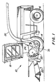
- a harvesting machine 10 shown in FIG. 1 in the manner of a self-propelled forage harvester is built on a frame 12 on carried by front and rear wheels 14 and 16 becomes.
- the harvesting machine 10 is operated by a Driver's cab 18, from which a crop receiving device 20 is visible.
- goods picked up from the ground e.g. B. corn, grass or the like is fed to a chopper drum 22, which it in small Chops pieces and gives it to a conveyor 24.
- the Well the harvesting machine 10 leaves for a vehicle traveling alongside Trailer over a rotating discharge chute 26.
- No further details of the harvesting machine 10 are required Description because it is known per se.
- the location of the Post-shredding device 28, however, is not critical so that they are also downstream of the conveyor device 24 can be provided.
- FIG. 2 schematically shows a view of a chopper drum 22 and a grinding device assigned to it, as seen when viewing the harvester 10 in Figure 1 (with respect to the direction of movement) results from the front.
- the Chopper drum 22 has a number across their width and their Scope of distributed knife 38 in cooperation with a rigid counter knife 46 through the crop receiving device Cut up 20 harvested crops.
- the chopper drum 22 comprises a central shaft 32, which over an end face of the Pulley 36 and belt, not shown, by a Motor of the harvesting machine 10 can be driven in rotation.
- the shaft 34 is supported by two on both sides of the chopper drum 22 arranged bearings on the frame 12 of the harvester 10.
- the sharpness of the knife 38 critical. Is the Distance from counter knife 46 too small, the knife 38 quickly dull or even damaged, if it is too large, it will harvested crop not properly chopped.
- the present invention relates to the second one Problem, the sharpness of the knife 38. To look for a certain operating time to be able to sharpen the knives 38 without the individual knives 38 or the entire chopper drum 22 need to remove is above the chopper 22 near the of the enveloping circle described by the knives 38 a grinding device provided which is essentially a grindstone 42, a grindstone holder 40 associated therewith and one Includes axis 44 on which the grindstone holder 40th is slidably mounted.
- the chopper drum is used 22 set in rotation, usually in reverse Direction of rotation and / or at reduced speed compared to normal chopping operation.
- the grindstone holder 40 with the attached grindstone 42 is made from a (not marked) resting or parking position, in the side is arranged next to the chopper drum 22, over the entire Width of the chopper drum 22 shifted.
- a grinding process is such that the Grindstone 42 several times across the width of the chopper drum 22 is operated.
- sensors are used according to the invention, for Detection of a worn grindstone 42 serve.
- Figure 3 an unused (brand new) grindstone 42 is shown, through which a wire loop 50 as an electrically conductive Element is misplaced.
- the wire loop 50 can Production of the grindstone 42, the z. B. by sintering or Pressing abrasive material and an adhesive filler takes place, be embedded in the grindstone 42.
- a plate 48 the grindstone holder 40 on which the grindstone 42 in the Usually attached by an adhesive connection is at least in the area through which the ends of the wire loop 50 are passed through, non-conductive.
- the plate 48 can in have a sufficiently large bore in this area or overall be electrically insulating.
- the plate 48 is preferably together with the grindstone 42 on the (in FIG 2 shown) remaining grindstone holder 40 releasably attached, around both parts (grindstone 42 and plate 48) if necessary to be able to exchange together.
- a Serve screw connection In particular, a Serve screw connection.
- the electrical conductivity of the wire loop 50 can be measured.
- the grindstone 42 is new, and the wire loop 50 is intact; thus there is an electrical contact between their ends.
- the same grindstone 42 is in shown worn condition. With the abrasive material is the wire loop 50 has also been ground off, and there is no more electrical contact between their ends. By Measuring the conductivity (or resistance) of the Wire loop 50 can reach the wear point of the Grindstone 42 are displayed.
- FIG 5 is a second embodiment of a grinding stone 42 according to the invention shown.
- the Grinding stone 42 are two wires 52 as electrically conductive Integrated elements that extend in the direction in which the grindstone 42 is fed to the knives 38. If the Grindstone 42 is worn, as shown in Figure 6, the ends of the wires 52 facing the knives 38 are exposed, and can be in contact with the knives 38 (or another conductive surface) come. By integrating the wires 52 in the grindstone 42 and measuring the resistance or The conductance between the wires 52 is therefore also one The wear point of the grindstone 42 can be displayed.
- FIG. 7 shows a third embodiment of a shown grinding stone according to the invention.
- this Embodiment is only a single wire 54 as electrical conductive element integrated in the grindstone 42. If the Grindstone 42 has reached its wear point, as in As shown in FIG. 8, the knife 38 is at the bottom drawn end of the wire 54 free, and can at rotating knife drum come into contact with the knives 38.
- the wear point of the grindstone detectable; in this case the resistance at certain Angular positions of the chopper drum 22 in which the wire 54 Has contact with a knife 38, much smaller than before.
- Figure 9 is a grindstone after a fourth Embodiment of the invention shown.
- a cavity 60 is provided, in which an optical sensor 56 is arranged.
- the grindstone 42 has reached its point of wear, is the grindstone material covering cavity 60 42 ground so that the cavity 60 - and thus the optical sensor 56 - incoming light 58 is exposed. On In this way, the point of wear can be easily demonstrated become.
- FIG. 13 shows a first embodiment of a Detection circuit shown in connection with Grinding stones 42 according to Figures 3 to 6 can be used.
- the Grindstone holder 40 with the grindstone attached 42 is provided with flexible cables 66 which one end to the Wires 50 and 52 integrated into the grindstone 42 are connected.
- One of the cables 66 is on the other end a certain potential (in the drawing Vehicle ground), and the other cable to a microprocessor 62 connected, which in turn is a display device 64 controls.
- the microprocessor 62 is stationary; so he will not shifted across the width of the chopper drum 22. Instead of the microprocessor 62 would also be a relay or the like can be used.
- the microprocessor 62 Based on the potential on the cable 66 the microprocessor 62 receives information that indicates whether the grindstone 42 has its wear point reached (then the cable is at 0 V) or not (then the cable is at any other potential).
- the grinding stone is monitored 42 continuously. With a grindstone 42, as in Figure 3 is shown, the resistance increases worn grindstone by interrupting the wire loop 50. On the other hand, the resistance decreases with one in figure 5 grinding stone 42 shown when the wear point is reached, because then the knife 38 (with appropriate angular position) create contact between the wires 52, while the resistance was higher before.
- FIG. 12 shows a second embodiment of a Detection circuit shown in connection with the in the Figures 7 and 8 shown grindstone 62 can be used.
- the in the grindstone 42 integrated wire 54 is over a single flexible cable 66 to a stationary microprocessor 62 connected to a display device 64 controls. If the grindstone 42 is worn out, is created at corresponding position of the knife 38 with the vehicle mass connected chopping drum 22 occasionally (with the corresponding Position of a knife 38) contact between wire 54 (and thus the cable 66) and the vehicle mass.
- the microprocessor 62 (the also through a simpler circuit, such as a relay or a Flip-flop could be replaced) recognizes this contact, and controls the display unit 64 accordingly. Also in this embodiment the condition of the grindstone is detected 42 continuously.
- FIG. 13 shows a third embodiment of a detection circuit, those with grinding stones 42 of FIGS. 5 and 6 is usable.
- the grindstone 42 is (e.g. after completion a grinding process) to the side of the chopper drum 22 been proceeded.
- the ends of the wires 52 at the bottom of the Grindstones 42 are in contact with a test element in shape a wire loop 70, and the top contacts of the Wires 52 are at a certain potential via a cable 68 laid, or via a further cable 72 to a microprocessor 62 connected, which controls a display unit 64.
- the Wire loop 70 and cables 68 and 72 are stationary.
- a fourth embodiment is one Detection circuit shown, which in combination with the in 7 and 8 shown grinding stone 42 can be used.
- the Contacts of the detection circuit are also stationary next to the chopper drum 22 arranged. For testing the grindstone 42 this must therefore after a grinding process next to the Chopping drum 22 (in its parking position) are brought.
- On contact 70 serving as test element is at ground potential, and a second contact 72 is with a microprocessor 62 connected, which controls a display unit 64. Is the Grinding stone 42 is still sufficiently worn, none comes electrical contact between the wire 54 in the grindstone 42 and the contact 70.
- the grindstone 42 reaches its wear point, the (occurs Ground potential) contact 70 in electrical Connection with the wire 54, so that the contact 72 on Is ground potential, and the microprocessor 62 with a corresponding signal is applied.
- the latter controls the display unit 64, and warns a user when it is worn out Whetstone 42
- the one embedded in the grindstone 42 forms Wire 50, 52, 54 together with the cables or contacts 66, 68, 70, 72, the microprocessor 62 and the display unit 64 a verification facility with which the achievement of Wear point of the grindstone 42 is detectable.
Landscapes
- Engineering & Computer Science (AREA)
- Mechanical Engineering (AREA)
- Life Sciences & Earth Sciences (AREA)
- Environmental Sciences (AREA)
- Constituent Portions Of Griding Lathes, Driving, Sensing And Control (AREA)
- Threshing Machine Elements (AREA)
Abstract
Description
- Fig. 1
- eine Erntemaschine mit einer Häckseltrommel mit Schleifvorrichtung in Seitenansicht und in schematischer Darstellung,
- Fig. 2
- eine Seitenansicht einer Schleifvorrichtung in den während des Schleifens eingenommenen Endpositionen,
- Fig. 3
- einen unbenutzten Schleifstein nach einer ersten Ausführungsform der Erfindung,
- Fig. 4
- den Schleifstein der Figur 3 in abgenutztem Zustand,
- Fig. 5
- einen unbenutzten Schleifstein nach einer zweiten Ausführungsform der Erfindung,
- Fig. 6
- den Schleifstein der Figur 5 in abgenutztem Zustand,
- Fig. 7
- einen unbenutzten Schleifstein nach einer dritten Ausführungsform der Erfindung,
- Fig. 8
- den Schleifstein der Figur 7 in abgenutztem Zustand,
- Fig. 9
- einen unbenutzten Schleifstein nach einer vierten Ausführungsform der Erfindung,
- Fig. 10
- den Schleifstein der Figur 9 in abgenutztem Zustand,
- Fig. 11
- einen Schleifstein mit angeschlossener Nachweisschaltung,
- Fig. 12
- einen Schleifstein mit einer anderen Nachweisschaltung,
- Fig. 13
- eine dritte Ausführungsform einer Nachweisschaltung, und
- Fig. 14
- eine vierte Ausführungsform einer Nachweisschaltung.
Claims (14)
- Schleifvorrichtung, mit einem Schleifstein (42) zum Schleifen eines Messers (38), gekennzeichnet durch eine Nachweiseinrichtung, mit der das Erreichen eines Verschleißpunktes des Schleifsteins (42) nachweisbar ist.
- Schleifvorrichtung nach Anspruch 1, dadurch gekennzeichnet, daß die Nachweiseinrichtung eine Anzeigeeinheit (64) steuert und/oder das Schleifen des Messers (38) ermöglicht bzw. unterbindet.
- Schleifvorrichtung nach Anspruch 1 oder 2, dadurch gekennzeichnet, daß die Nachweiseinrichtung ein in den Schleifstein (42) eingebettetes Element umfaßt, das beim Erreichen des Verschleißpunktes zerstört wird oder frei liegt, und daß die Nachweiseinrichtung den Zustand des Elements erfaßt.
- Schleifvorrichtung nach Anspruch 3, dadurch gekennzeichnet, daß die Nachweiseinrichtung ein im Schleifstein (42) angeordnetes elektrisch leitendes Element, insbesondere einen Draht (50, 52, 54), umfaßt.
- Schleifvorrichtung nach Anspruch 4, dadurch gekennzeichnet, daß das elektrisch leitende Element eine Schleife im Schleifstein (42) bildet, die beim Erreichen des Verschleißpunktes durchtrennt wird.
- Schleifvorrichtung nach Anspruch 4, dadurch gekennzeichnet, daß das elektrisch leitende Element ein im Schleifstein (42) angeordnetes Ende aufweist, das beim Erreichen des Verschleißpunktes frei liegt und in Kontakt mit dem Messer (38) und/oder einem Prüfelement (70) bringbar ist.
- Schleifvorrichtung nach einem der Ansprüche 4 bis 6, dadurch gekennzeichnet, daß das elektrisch leitende Element dauerhaft mit einer Nachweisschaltung, insbesondere einem Mikroprozessor (62), verbunden ist, die die Anzeigeeinheit (64) steuert und/oder das Schleifen des Messers (38) ermöglicht bzw. unterbindet.
- Schleifvorrichtung nach Anspruch 7, dadurch gekennzeichnet, daß der Schleifstein (42) über die Breite der Messer (38) verfahrbar ist, und daß das elektrisch leitende Element über ein flexibles Kabel (66) mit der Nachweisschaltung verbunden ist.
- Schleifvorrichtung nach einem der Ansprüche 4 bis 6, dadurch gekennzeichnet, daß der Schleifstein (42) zur Überprüfung, ob der Verschleißpunkt erreicht ist, in eine Meßposition, insbesondere eine Außerbetriebsstellung, verbracht wird, in der das elektrisch leitende Element mit einer Nachweisschaltung, beispielsweise einem Mikroprozessor (62), lösbar elektrisch verbunden ist, die die Anzeigeeinheit (64) steuert und/oder das Schleifen des Messers (38) ermöglicht bzw. unterbindet.
- Schleifvorrichtung nach Anspruch 9, dadurch gekennzeichnet, daß ein Prüfelement (70), mit dem ein beim Erreichen des Verschleißpunktes frei gewordenes Ende des elektrisch leitenden Elements im Schleifstein (42) in Kontakt kommt, an der Meßposition angeordnet ist.
- Schleifvorrichtung nach einem der Ansprüche 1 bis 3, dadurch gekennzeichnet, daß die Nachweiseinrichtung einen optischen Sensor (56) umfaßt.
- Schleifvorrichtung nach Anspruch 11, dadurch gekennzeichnet, daß der optische Sensor (56) an einem Hohlraum (60) des Schleifsteins (42) angeordnet ist, der beim Erreichen des Verschleißpunktes des Schleifsteins (42) gegenüber einfallendem Licht (58) geöffnet wird.
- Schleifvorrichtung nach Anspruch 11 oder 12, dadurch gekennzeichnet, daß der optische Sensor dauerhaft oder lösbar mit einer Nachweisschaltung, insbesondere einem Mikroprozessor (62), verbunden ist, die die Anzeigeeinheit (64) steuert und/oder das Schleifen des Messers (38) ermöglicht bzw. unterbindet.
- Erntemaschine, insbesondere selbstfahrender oder gezogener Feldhäcksler, mit einer Häckseltrommel (22) und einer Schleifvorrichtung nach einem der Ansprüche 1 bis 13.
Applications Claiming Priority (2)
| Application Number | Priority Date | Filing Date | Title |
|---|---|---|---|
| DE19910758A DE19910758A1 (de) | 1999-03-11 | 1999-03-11 | Schleifvorrichtung |
| DE19910758 | 1999-03-11 |
Publications (2)
| Publication Number | Publication Date |
|---|---|
| EP1034892A1 true EP1034892A1 (de) | 2000-09-13 |
| EP1034892B1 EP1034892B1 (de) | 2002-09-04 |
Family
ID=7900534
Family Applications (1)
| Application Number | Title | Priority Date | Filing Date |
|---|---|---|---|
| EP00104682A Expired - Lifetime EP1034892B1 (de) | 1999-03-11 | 2000-03-03 | Schleifvorrichtung |
Country Status (4)
| Country | Link |
|---|---|
| US (1) | US6430909B1 (de) |
| EP (1) | EP1034892B1 (de) |
| CA (1) | CA2297241C (de) |
| DE (2) | DE19910758A1 (de) |
Cited By (3)
| Publication number | Priority date | Publication date | Assignee | Title |
|---|---|---|---|---|
| EP2527087A1 (de) * | 2011-05-21 | 2012-11-28 | CLAAS Saulgau GmbH | Feldhäcksler mit einer Einrichtung zur Schneidschärfeerkennung |
| EP3769607A1 (de) * | 2019-07-24 | 2021-01-27 | CLAAS Selbstfahrende Erntemaschinen GmbH | Schleifstein und verfahren zum schleifen |
| DE102022101658A1 (de) | 2022-01-25 | 2023-07-27 | Deere & Company | Schleifeinrichtung |
Families Citing this family (14)
| Publication number | Priority date | Publication date | Assignee | Title |
|---|---|---|---|---|
| DE10035743A1 (de) * | 2000-07-22 | 2002-04-04 | Deere & Co | Schleifvorrichtung |
| DE10346116A1 (de) * | 2003-10-04 | 2005-04-21 | Deere & Co | Häckseleinrichtung für einen Feldhäcksler |
| US20070209344A1 (en) * | 2006-03-10 | 2007-09-13 | Textron Inc. | Sharpness monitor for indicating turf mower reel blade condition |
| US20130316770A1 (en) * | 2011-12-28 | 2013-11-28 | Agco Corporation | Knife-sharpening system for an infeed cutter of an agricultural impelment |
| DE102013101183A1 (de) * | 2013-02-07 | 2014-08-07 | Claas Selbstfahrende Erntemaschinen Gmbh | Landwirtschaftliche Arbeitsmaschine, insbesondere Feldhäcksler |
| DE102013211829B4 (de) * | 2013-06-21 | 2023-03-16 | Deere & Company | Element zum Abstützen und/oder Leiten von Erntegut in einer Erntemaschine |
| WO2018133984A1 (de) * | 2017-01-23 | 2018-07-26 | Voith Patent Gmbh | Schleifroboter zum schleifen elektrisch leitfähiger werkstücke und verfahren zum betrieb eines solchen |
| WO2018160663A2 (en) * | 2017-02-28 | 2018-09-07 | 3M Innovative Properties Company | Abrading tool for sensing vibration |
| BE1024803B1 (nl) * | 2017-05-12 | 2018-07-03 | Cnh Industrial Belgium Nv | Werkwijze voor het slijpen van messen van een landbouwvoertuig |
| DE102018128449A1 (de) * | 2018-11-13 | 2020-05-14 | Claas Saulgau Gmbh | Landwirtschaftliches Arbeitsgerät |
| US11279086B2 (en) * | 2019-07-15 | 2022-03-22 | Hamilton Sundstrand Corporation | Soft recoater blade and method of detecting wear |
| GB202007962D0 (en) * | 2020-05-28 | 2020-07-15 | Agco Int Gmbh | Forage harvester adjustment apparatus |
| GB202020465D0 (en) * | 2020-12-23 | 2021-02-03 | Agco Int Gmbh | Forage harvester |
| CN115634758B (zh) * | 2022-12-26 | 2023-03-07 | 中国农业科学院农业环境与可持续发展研究所 | 一种带动磨刀结构的秸秆粉碎装置 |
Citations (4)
| Publication number | Priority date | Publication date | Assignee | Title |
|---|---|---|---|---|
| US3490179A (en) * | 1967-03-06 | 1970-01-20 | Micromatic Hone Corp | Honing machine |
| US3964211A (en) * | 1975-07-31 | 1976-06-22 | Ex-Cell-O Corporation | Stone wear indication on a honing machine |
| DE3535473A1 (de) * | 1985-10-04 | 1987-04-09 | Krupp Gmbh | Verfahren und einrichtung zum erkennen von verschleiss und schneidenbruch bei werkzeugen mit schneiden aus hartstoff |
| EP0302565A2 (de) * | 1987-08-03 | 1989-02-08 | KADIA-Diamant Maschinen- und Werkzeugfabrik O. Kopp GmbH & Co. | Werkzeug zur spanabhebenden Bearbeitung |
Family Cites Families (8)
| Publication number | Priority date | Publication date | Assignee | Title |
|---|---|---|---|---|
| US3805228A (en) * | 1972-04-20 | 1974-04-16 | A Peeples | Vehicle brake lining wear indication apparatus |
| JPS5144073Y2 (de) * | 1972-07-24 | 1976-10-26 | ||
| US3908315A (en) * | 1973-10-19 | 1975-09-30 | Sundstrand Syracuse | Grinding machine systems |
| US4184145A (en) * | 1977-08-29 | 1980-01-15 | Jumpak Products, Inc. | Brake apparatus using light conductors to control remote wear indicators |
| SE433546B (sv) * | 1982-10-25 | 1984-05-28 | Asea Ab | Anordning for kontroll av kontaktavbrenning hos en elektrisk apparat anordning for kontroll av kontaktavbrenning hos en elektrisk apparat |
| US4991476A (en) | 1990-02-28 | 1991-02-12 | Ford New Holland, Inc. | Automatic knife sharpening method for forage harvesters |
| DE4212398A1 (de) * | 1992-04-13 | 1993-10-14 | Land Technik Ag Schoenebeck | Feldhäcksler |
| GB9506692D0 (en) * | 1995-03-31 | 1995-05-24 | New Holland Belguim Nv | Automatic knife sharpening method for forage harvesters |
-
1999
- 1999-03-11 DE DE19910758A patent/DE19910758A1/de not_active Withdrawn
-
2000
- 2000-01-13 US US09/483,010 patent/US6430909B1/en not_active Expired - Lifetime
- 2000-01-26 CA CA002297241A patent/CA2297241C/en not_active Expired - Fee Related
- 2000-03-03 DE DE50000431T patent/DE50000431D1/de not_active Expired - Lifetime
- 2000-03-03 EP EP00104682A patent/EP1034892B1/de not_active Expired - Lifetime
Patent Citations (4)
| Publication number | Priority date | Publication date | Assignee | Title |
|---|---|---|---|---|
| US3490179A (en) * | 1967-03-06 | 1970-01-20 | Micromatic Hone Corp | Honing machine |
| US3964211A (en) * | 1975-07-31 | 1976-06-22 | Ex-Cell-O Corporation | Stone wear indication on a honing machine |
| DE3535473A1 (de) * | 1985-10-04 | 1987-04-09 | Krupp Gmbh | Verfahren und einrichtung zum erkennen von verschleiss und schneidenbruch bei werkzeugen mit schneiden aus hartstoff |
| EP0302565A2 (de) * | 1987-08-03 | 1989-02-08 | KADIA-Diamant Maschinen- und Werkzeugfabrik O. Kopp GmbH & Co. | Werkzeug zur spanabhebenden Bearbeitung |
Cited By (5)
| Publication number | Priority date | Publication date | Assignee | Title |
|---|---|---|---|---|
| EP2527087A1 (de) * | 2011-05-21 | 2012-11-28 | CLAAS Saulgau GmbH | Feldhäcksler mit einer Einrichtung zur Schneidschärfeerkennung |
| US9801342B2 (en) | 2011-05-21 | 2017-10-31 | Claas Saulgau Gmbh | Method for determining the sharpness of cutting edges of chopper blades |
| EP3769607A1 (de) * | 2019-07-24 | 2021-01-27 | CLAAS Selbstfahrende Erntemaschinen GmbH | Schleifstein und verfahren zum schleifen |
| DE102022101658A1 (de) | 2022-01-25 | 2023-07-27 | Deere & Company | Schleifeinrichtung |
| BE1030161A1 (de) | 2022-01-25 | 2023-07-28 | Deere & Co | Schleifeinrichtung |
Also Published As
| Publication number | Publication date |
|---|---|
| EP1034892B1 (de) | 2002-09-04 |
| CA2297241C (en) | 2004-06-22 |
| CA2297241A1 (en) | 2000-09-11 |
| US6430909B1 (en) | 2002-08-13 |
| DE19910758A1 (de) | 2000-09-14 |
| DE50000431D1 (de) | 2002-10-10 |
Similar Documents
| Publication | Publication Date | Title |
|---|---|---|
| EP1034892B1 (de) | Schleifvorrichtung | |
| EP2008508B1 (de) | Erntemaschine mit Güteüberwachung der Schneiden | |
| EP2764767B1 (de) | Landwirtschaftliche Erntemaschine, insbesondere Feldhäcksler | |
| EP2436258B1 (de) | Landwirtschaftlicher Selbstfahrhäcksler mit Vorrichtung zur Ermittlung der Schärfe von Schneidmessern | |
| BE1022370B1 (de) | Anordnung zur erfassung der scharfe von hackselmessern | |
| DE102013201633B3 (de) | Einrichtung zur Verstellung der Position einer Gegenschneide gegenüber einer Häckseleinrichtung | |
| EP1442652A1 (de) | Einrichtung zur Messung und/oder Überprüfung des Abstands zwischen einer Gegenschneide und einem Häckselmesser | |
| EP1174021A1 (de) | Schleifvorrichtung | |
| EP1174020B1 (de) | Schleifvorrichtung | |
| DE102004016089B4 (de) | Einrichtung zur Verstellung der Position einer Gegenschneide gegenüber einer Häckseleinrichtung | |
| DE102017201423A1 (de) | Anordnung zur Erkennung des Verschleißgrades von Häckselmessern einer Häckseltrommel eines Feldhäckslers | |
| EP0217418B1 (de) | Fremdkörpererkennungseinrichtung für landwirtschaftliche Erntemaschinen | |
| DE102020129795A1 (de) | Feldhäcksler mit Konditionierwalzen und Verschleißsensor | |
| EP2329705A1 (de) | Häckselmesser für einen Feldhäcksler und Anordnung zur Erfassung von dessen Schärfe | |
| EP1145617B1 (de) | Schleifvorrichtung | |
| EP1537772B1 (de) | Häckselvorrichtung mit Schleifvorrichtung | |
| BE1028680B1 (de) | Steueranordnung für eine Schleifeinrichtung und eine Einrichtung zur Verstellung der Position einer Gegenschneide gegenüber einer Häckseleinrichtung eines Feldhäckslers | |
| EP1396184A1 (de) | Vorrichtung zum Zerkleinern von landwirtschaftlichem Erntegut | |
| EP3861849B1 (de) | Landwirtschaftliche arbeitsmaschine mit einer messanordnung, messanordnung für die landwirtschaftliche arbeitsmaschine und verfahren zum messen einer kontur eines sich bewegenden bauteils der landwirtschaftlichen arbeitsmaschine | |
| DE4023113A1 (de) | Verfahren zum feststellen der schaerfe von haeckselmessern | |
| DE102014221465A1 (de) | Schleifeinrichtung | |
| EP4122313A1 (de) | Verfahren zur bestimmung des verschleisszustandes einer an einem gegenschneideträger angeordneten gegenschneide sowie selbstfahrender feldhäcksler | |
| DE19716183A1 (de) | Verfahren und Vorrichtung zur Abstandsmessung bei Landmaschinen | |
| DE102017105439A1 (de) | Häckselwerk eines Feldhäckslers, Häckselmesser für ein solches Häckselwerk und Feldhäcksler | |
| DE102021120665A1 (de) | Anordnung zur Erfassung der Schärfe und/oder des Abstands von Messern einer Häckseltrommel eines Feldhäckslers und deren Drehstellung und/oder Drehzahl |
Legal Events
| Date | Code | Title | Description |
|---|---|---|---|
| PUAI | Public reference made under article 153(3) epc to a published international application that has entered the european phase |
Free format text: ORIGINAL CODE: 0009012 |
|
| AK | Designated contracting states |
Kind code of ref document: A1 Designated state(s): BE DE DK FR GB IT |
|
| AX | Request for extension of the european patent |
Free format text: AL;LT;LV;MK;RO;SI |
|
| 17P | Request for examination filed |
Effective date: 20010303 |
|
| AKX | Designation fees paid |
Free format text: BE DE DK FR GB IT |
|
| 17Q | First examination report despatched |
Effective date: 20010606 |
|
| GRAG | Despatch of communication of intention to grant |
Free format text: ORIGINAL CODE: EPIDOS AGRA |
|
| GRAG | Despatch of communication of intention to grant |
Free format text: ORIGINAL CODE: EPIDOS AGRA |
|
| GRAH | Despatch of communication of intention to grant a patent |
Free format text: ORIGINAL CODE: EPIDOS IGRA |
|
| GRAH | Despatch of communication of intention to grant a patent |
Free format text: ORIGINAL CODE: EPIDOS IGRA |
|
| GRAA | (expected) grant |
Free format text: ORIGINAL CODE: 0009210 |
|
| AK | Designated contracting states |
Kind code of ref document: B1 Designated state(s): BE DE DK FR GB IT |
|
| REG | Reference to a national code |
Ref country code: GB Ref legal event code: FG4D Free format text: NOT ENGLISH |
|
| REF | Corresponds to: |
Ref document number: 50000431 Country of ref document: DE Date of ref document: 20021010 |
|
| ET | Fr: translation filed | ||
| PG25 | Lapsed in a contracting state [announced via postgrant information from national office to epo] |
Ref country code: DK Free format text: LAPSE BECAUSE OF FAILURE TO SUBMIT A TRANSLATION OF THE DESCRIPTION OR TO PAY THE FEE WITHIN THE PRESCRIBED TIME-LIMIT Effective date: 20021204 |
|
| GBT | Gb: translation of ep patent filed (gb section 77(6)(a)/1977) |
Effective date: 20021202 |
|
| PLBE | No opposition filed within time limit |
Free format text: ORIGINAL CODE: 0009261 |
|
| STAA | Information on the status of an ep patent application or granted ep patent |
Free format text: STATUS: NO OPPOSITION FILED WITHIN TIME LIMIT |
|
| 26N | No opposition filed |
Effective date: 20030605 |
|
| PGFP | Annual fee paid to national office [announced via postgrant information from national office to epo] |
Ref country code: IT Payment date: 20090327 Year of fee payment: 10 |
|
| PG25 | Lapsed in a contracting state [announced via postgrant information from national office to epo] |
Ref country code: IT Free format text: LAPSE BECAUSE OF NON-PAYMENT OF DUE FEES Effective date: 20100303 |
|
| PGFP | Annual fee paid to national office [announced via postgrant information from national office to epo] |
Ref country code: FR Payment date: 20140317 Year of fee payment: 15 |
|
| PGFP | Annual fee paid to national office [announced via postgrant information from national office to epo] |
Ref country code: GB Payment date: 20140327 Year of fee payment: 15 |
|
| GBPC | Gb: european patent ceased through non-payment of renewal fee |
Effective date: 20150303 |
|
| REG | Reference to a national code |
Ref country code: FR Ref legal event code: ST Effective date: 20151130 |
|
| PG25 | Lapsed in a contracting state [announced via postgrant information from national office to epo] |
Ref country code: GB Free format text: LAPSE BECAUSE OF NON-PAYMENT OF DUE FEES Effective date: 20150303 |
|
| PG25 | Lapsed in a contracting state [announced via postgrant information from national office to epo] |
Ref country code: FR Free format text: LAPSE BECAUSE OF NON-PAYMENT OF DUE FEES Effective date: 20150331 |
|
| PGFP | Annual fee paid to national office [announced via postgrant information from national office to epo] |
Ref country code: BE Payment date: 20160328 Year of fee payment: 17 |
|
| REG | Reference to a national code |
Ref country code: BE Ref legal event code: MM Effective date: 20170331 |
|
| PG25 | Lapsed in a contracting state [announced via postgrant information from national office to epo] |
Ref country code: BE Free format text: LAPSE BECAUSE OF NON-PAYMENT OF DUE FEES Effective date: 20170331 |
|
| PGFP | Annual fee paid to national office [announced via postgrant information from national office to epo] |
Ref country code: DE Payment date: 20190331 Year of fee payment: 20 |
|
| REG | Reference to a national code |
Ref country code: DE Ref legal event code: R071 Ref document number: 50000431 Country of ref document: DE |