EP1033693A2 - Rear and side view monitor with camera for a vehicle - Google Patents
Rear and side view monitor with camera for a vehicle Download PDFInfo
- Publication number
- EP1033693A2 EP1033693A2 EP00104078A EP00104078A EP1033693A2 EP 1033693 A2 EP1033693 A2 EP 1033693A2 EP 00104078 A EP00104078 A EP 00104078A EP 00104078 A EP00104078 A EP 00104078A EP 1033693 A2 EP1033693 A2 EP 1033693A2
- Authority
- EP
- European Patent Office
- Prior art keywords
- vehicle
- image
- road
- rudder angle
- monitoring area
- Prior art date
- Legal status (The legal status is an assumption and is not a legal conclusion. Google has not performed a legal analysis and makes no representation as to the accuracy of the status listed.)
- Granted
Links
Images




Classifications
-
- H—ELECTRICITY
- H04—ELECTRIC COMMUNICATION TECHNIQUE
- H04N—PICTORIAL COMMUNICATION, e.g. TELEVISION
- H04N7/00—Television systems
- H04N7/18—Closed-circuit television [CCTV] systems, i.e. systems in which the video signal is not broadcast
- H04N7/183—Closed-circuit television [CCTV] systems, i.e. systems in which the video signal is not broadcast for receiving images from a single remote source
-
- G—PHYSICS
- G08—SIGNALLING
- G08G—TRAFFIC CONTROL SYSTEMS
- G08G1/00—Traffic control systems for road vehicles
- G08G1/16—Anti-collision systems
- G08G1/167—Driving aids for lane monitoring, lane changing, e.g. blind spot detection
Definitions
- the present invention generally relates to a vehicle-applied rear-and-side monitoring system and vehicle-applied rear-and-side monitoring and alarming system and more particularly, to a vehicle-applied rear-and-side monitoring system, which monitors a rear-and-side of a running vehicle, i.e. own vehicle, such as a motor vehicle by taking an image of a rear-and-side road view of the own vehicle by an image taking means such as a video camera and the like set on the own vehicle and by detecting a following vehicle being approaching the own vehicle from the rear-and-side with use of the taken road image, and to a vehicle-applied rear-and-side monitoring and alarming system, which alarms a driver when the above monitoring system have detected a danger.
- a running vehicle i.e. own vehicle, such as a motor vehicle by taking an image of a rear-and-side road view of the own vehicle by an image taking means such as a video camera and the like set on the own vehicle and by detecting a following vehicle being approaching the own
- JP '562 Japanese Patent No. 2641562
- JP '096 Japanese Patent Application Laid-open No. 6-107096
- JP '769 Japanese Patent Application Laid-open No. 7-50769
- the above system recognizes a lane marking on the road so as to distinguish traffic lanes with use of a road image taken by a video camera and sets a monitoring area on the neighboring lane.
- This system is intended to reduce an image-processing amount for detecting the following vehicle in the neighboring lane, i.e. in the monitoring area, so that the following vehicle in the neighboring lane can be detected fast and surely.
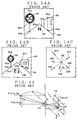
- JP '096 and JP '769 disclose the system applying an optical flow, which will be briefly described with reference to FIGS.13 and 14.
- FIG.13 is a block diagram showing a prior art vehicle-applied rear-and-side monitoring and alarming system, wherein 10 indicates an image taking portion used as an image taking means and has a video camera 11 for example. And, 30 is a data processing portion use as an arithmetical unit, and 42 is a speaker use as an alarming means.
- the image taking portion 10 is arranged at a required position on a rear side, e.g. over the trunk room, of the own vehicle for taking a rear-and-side road view of the vehicle.
- the data processing portion 30 has CPU 31 (i.e. a central processing unit) to operate according to a program, ROM 32 to keep the program for the CPU 31 and a preset value, and RAM 33 to temporary keep required data for calculation by the CPU 31.
- the speaker 42 is arranged inside the own vehicle and raises a voice or an alarm sound on the basis of a signal from the CPU 31 of the data processing portion 30 so as to have the driver take notice of the danger.
- FIGS.14A-14C are explanatory illustrations showing change of a rear-and-side road image taken by the image taking portion 10.
- FIG.14A is of at a time t
- FIG.14B is of at a time t+ ⁇ t.
- 200 indicates a following vehicle running at the rear-and-side of the own vehicle
- 300 indicates a road sign standing on one side of the road 500
- 400 indicates a building neighboring the road 500.
- Speed vectors connecting the corresponding subject points are obtained as optical flows such as 201F,202F,301F,302F,303F,401F and 402F shown in FIG. 14C.
- the optical flow is acknowledged to be radially formed from an infinity point in the road image, which infinity point is defined as FOE (i.e. Focus of Expansion).
- FOE Focus of Expansion
- the FOE is positioned at the opposite point to the running direction of the vehicle.
- the optical flows 201F and 202F of the following vehicle 200 are vectors in a diverging direction, the following vehicle is judged to be approaching to the own vehicle.
- Length of the optical flow is in proportion to a distance per unit time, i.e. speed difference, between the own vehicle and the object and also in proportion to a distance itself between the own vehicle and the object. This will be described with reference to FIG.15.
- FIG.15 is a theoretical scheme showing an optical arrangement, wherein 11a indicates a lens of the video camera of the image taking portion 10, 11b indicates an image plane of the video camera, f indicates a distance from the lens 11a to the image plane 11b, P(Xa,Ya,Za) indicates a point on the following vehicle, and p(xa,ya) on the image plane 11b indicates a corresponding point to the point P.
- Za in the equation (4) is a speed difference or a relative speed between the following vehicle 200 (FIG.14A) and the own vehicle.
- the x component u of the optical flow can be given with the following equation (6).
- Ya i.e. the Y-axis of the point P, can be obtained similarly.
- the data processing portion 30 judges that the object on the road exists near the own vehicle or is approaching thereto with a high speed when the optical flow is a vector in a diverging direction and simultaneously is large, and that degree of danger is high.
- Optical flows of objects on the image can be obtained similarly to the above, and thereby degree of danger with each of the objects can be judged. And, a driver can be given an alarm according to the degree of danger, thereby preventing a dangerous state or an actual trouble.
- the monitoring area is separated, by lane markings defining the own vehicle running lane, to an area of the own vehicle running lane and an area of the neighboring lanes on both sides of the own vehicle running lane so that required processing time can be decreased thereby to attain high speed processing.
- the FOE is detected by extending the lane markings, and the following vehicle 200 in the own vehicle running lane area or in the neighboring lane area is detected by obtaining its optical flow, and degree of danger with the following vehicle 200 running at the rear or on the neighboring lanes is judged according to length of the optical flow.
- the correlation method which requires enormous calculation since a corresponding point of each of the picture elements in the image is searched for calculating a correlation value.
- the method has, however, an advantage that the optical flow can be relatively correctly obtained even though the image is complicated.
- a monitoring area is considered to be set in order to decrease the processing time and to raise an accuracy of the detection.
- the monitoring area could not be set during night or a rainy day since lane markings is difficult to be recognized.
- an object of the present invention is to provide a vehicle-applied rear-and-side monitoring system wherein an monitoring area can be set correspondingly to the traffic lanes in the road image without using the lane markings to be detected in the road image and also a vehicle-applied rear-and-side monitoring and alarming system which gives a drive an alarm in case that the vehicle-applied rear-and-side monitoring system detected the danger.
- a vehicle-applied rear-and-side monitoring system to be set on a first vehicle includes: an image taking means 10 for taking an image of a rear-and-side road view of the first vehicle so as to obtain a road image every definite period of time; a monitoring area setting means 31-1 for setting a monitoring area in the road image for monitoring a second vehicle; an optical flow detecting means 31-2 for detecting an optical flow deriving from the second vehicle to be in the monitoring area in two serial road images so as to monitor a relative position between the first vehicle and the second vehicle; and a rudder angle detecting means 51 for detecting a rudder angle of the first vehicle, wherein the monitoring area setting means sets the monitoring area inside or outside an area enclosed with lines connecting two lane marking positions, where two lane markings on both sides of a first vehicle running lane in the road image cross a periphery of the road image, to an infinity point in the
- the image taking means 10 takes an image of a rear-and-side road view of the first vehicle so as to obtain a road image every definite period of time
- the monitoring area setting means 31-1 sets a monitoring area in the road image for monitoring a second vehicle.
- the optical flow detecting means 31-2 detects an optical flow deriving from the second vehicle to be in the monitoring area in two serial road images so as to monitor a relative position between the first vehicle and the second vehicle.
- the monitoring area setting means sets the monitoring area inside or outside an area enclosed with lines connecting two lane marking positions, where two lane markings on both sides of a first vehicle running lane in the road image cross a periphery of the road image, to an infinity point in the road image, said infinity point corresponding to the rudder angle detected by the rudder angle detecting means 51.
- the monitoring area can be set inside or outside an area enclosed with lines connecting the two lane marking positions to the infinity point without detecting the lane markings themselves. Further, since the infinity point which moves as time passed is set correspondingly to the own vehicle's rudder angle, the monitoring area can be almost correctly set.
- the monitoring area setting means has a rudder angle vs. infinity point memorizing means 32-1 for memorizing the infinity point correspondingly to the rudder angle of the first vehicle and decides the infinity point corresponding to the rudder angle detected by the rudder angle detecting means by reading out the infinity point from the rudder angle vs. infinity point memorizing means.
- the monitoring area is set accordingly to the infinity point which is stored accordingly to the rudder angle and is read out correspondingly to the own vehicle's rudder angle, the monitoring area can be set only by detecting the own vehicle's rudder angle, without a bothersome calculation processing.
- the monitoring area setting means has a rudder angle vs. lane marking position memorizing means 32-2 for memorizing the two lane marking positions correspondingly to the rudder angle of the first vehicle and decides the two lane marking positions corresponding to the rudder angle detected by the rudder angle detecting means by reading out the two lane marking positions from the rudder angle vs. lane marking position memorizing means.
- the monitoring area since the monitoring area is set accordingly to the two lane marking positions which are stored accordingly to the rudder angle and is read out correspondingly to the own vehicle's rudder angle, the monitoring area can be set only by detecting the own vehicle's rudder angle, without a bothersome calculation processing.
- the monitoring area setting means decides the two lane marking positions by image-processing a periphery of the road image taken by the image taking means.
- the monitoring area is set by using the two lane marking positions which are decided by image-processing the periphery of the road image taken by the image taking means, the monitoring area can be set only by image-processing a small area, without a bothersome calculation processing.
- a vehicle-applied rear-and-side monitoring system to be set on a first vehicle includes: an image taking means 10 for taking an image of a rear-and-side road view of the first vehicle so as to obtain a road image every definite period of time; a monitoring area setting means 31-1 for setting a monitoring area in the road image for monitoring a second vehicle; and an optical flow detecting means 31-2 for detecting an optical flow deriving from the second vehicle to be in the monitoring area in two serial road images so as to monitor a relative position between the first vehicle and the second vehicle, wherein the monitoring area setting means has a straight line detecting means 31-3 for detecting a plurality of straight lines by executing an edge processing to the road image and an infinity point deciding means 31-4 for deciding an intersection of the plurality of straight lines as an infinity point in the road image and sets the monitoring area inside or outside an area enclosed with lines connecting two lane marking positions,
- the monitoring area can be set inside or outside an area enclosed with lines connecting the two lane marking positions to the infinity point without detecting the lane markings themselves. Further, since the infinity point can be set simply and correctly, the monitoring area can be almost correctly set.
- a vehicle-applied rear-and-side monitoring system to be set on a first vehicle includes: an image taking means 10 for taking an image of a rear-and-side road view of the first vehicle so as to obtain a road image every definite period of time; a monitoring area setting means 31-1 for setting a monitoring area in the road image for monitoring a second vehicle; and an optical flow detecting means 31-2 for detecting an optical flow deriving from the second vehicle to be in the monitoring area in two serial road images so as to monitor a relative position between the first vehicle and the second vehicle, wherein the monitoring area setting means has a stationary object's optical flow detecting means 31-5 for detecting a plurality of optical flows deriving from stationary objects in two serial road images and an infinity point deciding means 31-6 for deciding a convergent point of the plurality of optical flows as an infinity point in the road image and sets the monitoring area inside or outside an area
- the monitoring area can be set inside or outside an area enclosed with lines connecting the two lane marking positions to the infinity point without detecting the lane markings themselves. Further, since the infinity point can be set simply and correctly, the monitoring area can be almost correctly set.
- a vehicle-applied rear-and-side monitoring system to be set on a first vehicle includes: an image taking means 10 for taking an image of a rear-and-side road view of the first vehicle so as to obtain a road image every definite period of time; a monitoring area setting means 31-1 for setting a monitoring area in the road image for monitoring a second vehicle; an optical flow detecting means 31-2 for detecting an optical flow deriving from the second vehicle to be in the monitoring area in two serial road images so as to monitor a relative position between the first vehicle and the second vehicle; a rudder angle detecting means 51 for detecting a rudder angle of the first vehicle; and a speed detecting means 53 for detecting speed of the first vehicle, wherein the monitoring area setting means has a road form calculating means 31-7 for calculating a passed road form on the basis of a past rudder angle detected by the rudder angle detecting means and
- the monitoring area can be set inside or outside an area enclosed with two curved lines, which start from the two lane marking positions, of the passed road form. Further, since the infinity point can be set simply and correctly, the monitoring area can be almost correctly set.
- the monitoring area setting means selects the two lane marking positions correspondingly to the rudder angle of the first vehicle.
- the monitoring area is set by selecting the two lane marking positions according to the own vehicle's rudder angle to have been detected, a part, of the monitoring area, near the own vehicle can be correct.
- the monitoring area setting means has a rudder angle vs. lane marking position memorizing means 32-2 for memorizing the two lane marking positions correspondingly to the rudder angle of the first vehicle and decides the two lane marking positions corresponding to the rudder angle detected by the rudder angle detecting means by reading out the two lane marking positions from the rudder angle vs. lane marking position memorizing means.
- the monitoring area is set accordingly to the two lane marking positions which are stored accordingly to the rudder angle and is read out correspondingly to the own vehicle's rudder angle, a part, of the monitoring area, near the own vehicle can be set only by detecting the own vehicle's rudder angle, without a bothersome calculation processing.
- the monitoring area setting means decides the two lane marking positions by image-processing a periphery of the road image taken by the image taking means.
- the monitoring area is set accordingly to the two lane marking positions which are stored accordingly to the rudder angle and is read out correspondingly to the own vehicle's rudder angle, a part, of the monitoring area, near the own vehicle can be set only by detecting the own vehicle's rudder angle, without a bothersome calculation processing.
- a vehicle-applied rear-and-side monitoring and alarming system to be set on a first vehicle includes: the vehicle-applied rear-and-side monitoring system with any one of the above preceding aspects, wherein the monitoring area is set outside the area enclosed with the lines; a blinker detecting means 52 for detecting an action and an indicating direction of a blinker; and an alarming means 40 for alarming a driver when a second vehicle exists within the monitoring area positioned in the indicating direction detected by the blinker detecting means as a result of monitoring the rear-and-side road view by means of the vehicle-applied rear-and-side monitoring system.
- the monitoring area is set outside the area enclosed with the lines connecting the two lane marking positions to the infinity point without detecting the lane markings themselves, only a short processing time period for raising an alarm is required.
- FIG.2 is a block diagram showing the vehicle-applied rear-and-side monitoring and alarming system in accordance with the present invention, wherein 10 is an image taking portion to be an image taking means, 20 is a memory portion to keep image data and the like from the image taking portion 10, 30 is a data processing portion to execute, based on image information from the image taking portion 10, an image processing and a processing of monitoring a relative position with a following vehicle and so on, 40 is an alarming portion to be an alarming means to raise an alarm, and 50 is a signal input portion to input signal showing operation information of a running direction change of an own vehicle (hereinafter "the vehicle” or "the own vehicle”).
- the vehicle or the own vehicle
- the image taking portion 10 has a video camera 11. And, the video camera 11 has a lens (indicated with reference numeral 11a in FIG.13) and an image plane (11b in FIG.13).
- the video camera 11 of the image taking portion 10 is mounted on a trunk portion or a rear end portion of the own vehicle and is directed rearward, which the video camera 11 is capable of taking an image of a rear-and-side road view of the vehicle and outputs rear-and-side road image information toward the CPU 31 (described later) of the data processing portion 30.
- the memory portion 20 has a first frame memory 21 and a second frame memory 22, which keep the road image information from the image taking portion 10, and a diverging optical flow memory 23 to keep a diverging optical flow.
- the first frame memory 21 and the second frame memory 22 consisting of the memory portion 20 are made of a matrix memory having picture elements of 512 x 512. And, the memories 21-23 are connected, with a read/write function, to the the CPU 31 of the data processing portion 30.
- the data processing portion 30 has the CPU 31 (i.e. a central processing unit) to operate according to a program, ROM 32 to keep the program for the CPU 31 and a preset value, and RAM 33 to temporary keep required data for calculation by the CPU 31.
- CPU 31 i.e. a central processing unit
- ROM 32 to keep the program for the CPU 31 and a preset value
- RAM 33 to temporary keep required data for calculation by the CPU 31.
- the alarming portion 40 has a display 41 and a speaker 42.
- the display 41 is made of LCD (i.e. a liquid crystal display) and the like, which display 41 displays an image taken by the video camera 11 or also displays a message of danger when the data processing portion 30 (CPU 31) has judged that there is a danger of scraping against the following vehicle so as to have a driver take notice of the danger.
- the speaker 42 raises a voice as a voice guidance or an alarm sound on the basis of an aural signal from the data processing portion 30 also so as to have the driver take notice of the danger.
- the signal input portion 50 has a rudder angle sensor 51 to be a rudder angle detecting means which detects a steering angle as a rudder angle or a rudder angle itself of a rudder wheel (i.e. generally front wheels) and a blinker detecting switch 52 to be a blinker detecting means which detects operation and indicating direction of a blinker system by a driver.
- the rudder angle sensor 51 detects turning information of the vehicle
- the blinker detecting switch 52 detects turning indication information of the blinker system which is operated by a driver when the vehicle is going to turn right or left.
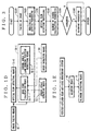
- Step S110 an image taking processing is executed at Step S110, wherein the CPU 31 of the data processing portion 30 functions as the monitoring area setting means 31-1.
- the image taking processing at Step S110 is of a process to take the image information required for setting the monitoring area and makes a rear-and-side road image shown in FIG.4.
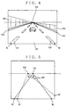
- FIG.4 is one example of a road image taken by a video camera 11 directed rearward and installed at a rear portion of the own vehicle running on a highway.
- a road 500, lane markings 510 and 520 which are made of a broken line and separate an own vehicle running lane from its neighboring lanes, lane markings 530 and 540 which are made of serial lines and limit the traffic lanes, and walls 600 on both sides of the road 500 disappear at a point positioned in the horizontal center and at vertically 1/3 position from the top of the road image, which point is defined as FOE (Focus of Expansion).
- the road image information is stored in the first frame memory 21 of the memory portion 20.
- the right in the road image corresponds to the left in the running direction and the left in the road image corresponds to the right in the running direction.
- right and left in the road image will be dealt with.
- a FOE line L indicating vertical position of the above FOE is fixed to, for example, 100m behind the vehicle according to a field angle of the video camera 11, an aberration of its lens, and setting parameters (i.e. height and dip) of the video camera 11 and the like.
- lane marking positions W1 and W2 where the lane markings 510 and 520 cross the periphery of the road image are also fixed according to the field angle of the video camera 11, the aberration of the lens, and setting parameters (i.e. height and dip) of the video camera 11 and the like. Therefore, the monitoring area of the own vehicle running lane can be set within an area enclosed with lines connecting the lane marking positions W1 and W2 to the FOE, i.e. an infinity point, and monitoring areas of the neighboring lanes can be set within areas enclosed with lines connecting the lane marking positions W1 and W2 and the FOE line L.
- the FOE line L does not change between serial two road images taken with a difference of a definite period of time even if the vehicle changes its running direction
- the FOE changes its position between the above two serial road images if the vehicle changes its running direction.
- the infinity point FOE in the preceding road image shifts to FOE' shown in FIG.5.
- the lane marking positions W1 and W2 on the periphery of the image do not change as far as the vehicle is running straight in the middle of a straight lane, the lane marking positions W1 and W2 in the preceding road image shift to the new lane marking positions W1 and W2 shown in FIG.5 in case that the vehicle has turned right.
- the following vehicle 200 which is running near the infinity point FOE may be misjudged to be running on the own vehicle running lane even if the following vehicle 200 is actually running on the neighboring lane because an image of the following vehicle 200 is very small.
- the following vehicle 200 running on the own vehicle running lane may be misjudged to be running on the neighboring lane.
- An area including the following vehicle running near the own vehicle can be, however, correctly judged even if the lane marking positions W1 and W2 are used instead of the new lane marking positions W1 and W2 because the image of the following vehicle is relatively large.
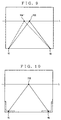
- the following vehicle 200 can be correctly monitored, whichever lanes, namely the own vehicle running lane or the neighboring lanes, the following vehicle 200 is running by setting a monitoring area for the own vehicle running lane and another monitoring area for the neighboring lanes inside and outside, respectively, the area enclosed with lines connecting the lane marking positions W1 and W2 to the FOE' as a substitute of the FOE.
- the above monitoring areas shall be strictly set inside and outside, respectively, the area enclosed with lines connecting the new lane marking positions W1 and W2 to the FOE'.
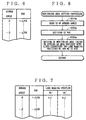
- the ⁇ FOE can be determined by reading out the ⁇ FOE addressed with the rudder angle, while having a table of rudder angle vs. ⁇ FOE as a rudder angle vs. infinity point memorizing means 32-1 in the ROM 32 as shown in FIG.6.
- the former does not require a storage area in ROM, and the latter does not require calculation and therefore is suitable for high speed processing.
- the new lane marking positions W1 and W2 can be determined by reading out the new lane marking positions W1 and W2 addressed with the rudder angle, while having a table of rudder angle and ⁇ FOE vs. the coordinates of new lane marking positions W1 and W2 , which have calculated, as a rudder angle vs. lane marking position memorizing means 32-2 in the ROM 32 as shown in FIG.7.
- Step S120 a monitoring area setting processing is executed at Step S120.
- the monitoring area setting processing is executed according to the flow chart shown in FIG.8.
- the monitoring area setting processing first, the rudder angle data, to which the analog to digital conversion has been executed to the rudder angle signal from the sensor 51, is read out at Step S210a, and the rudder angle is detected.
- Step S220a ⁇ FOE is read out from the table of FIG.6 according to the rudder angle to be used as the address, and the new infinity point FOE' having moved by ⁇ FOE is decided.
- Step S230a the monitoring area is set inside or outside an area enclosed with lines connecting the lane marking positions W1 and W2 to the infinity point FOE' decided at Step S220a, as is shown in FIG.9.
- the lane marking positions of W1 and W2 is used in the flow chart of FIG.8.
- the lane marking positions W1 and W2 which shift according to the rudder angle may be used at Step S230a by reading out the lane marking positions W1 and W2 from the table of FIG.7 according to the rudder angle.
- the monitoring area can be similarly set inside or outside an area enclosed with lines connecting the lane marking positions W1 and W2 to the infinity point FOE' decided at Step S220a.
- a small image processing area corresponding to an area where the lane marking positions move about, may be provided along the periphery of the road image so that the lane marking positions W1 and W2 are detected by the image processing of the image processing area due to higher luminance of the two lane marking positions than that of the other part.
- One method of deciding the infinity point FOE is that a plurality of straight lines of the lane marking 530 and 540, the walls 600, and the like on the road 500 are detected after executing an edge processing and Hough transform for the road image and an intersection of the straight lines are decided as the infinity point.
- a plurality of optical flows of stationary objects in serial two road images are detected, and a convergent point of the optical flows is decided as the infinity point.
- the CPU 31 of the data processing portion 30 functions as a straight line detecting means 31-3 which operates on the fixed program and detects the plurality of straight lines by executing the edge processing for the road image taken by the video camera 11 and also functions as an infinity point deciding means 31-4 which decides the intersection of the straight lines as the infinity point in the road image.
- the processing for detecting the straight line itself is generally known.
- the CPU 31 functions as a stationary object's optical flow detecting means 31-5 which operates on the fixed program and detects the plurality of optical flows of stationary objects in serial two road images taken by the video camera 11 and also functions as an infinity point deciding means 31-6 which decides the intersection of the optical flows as the infinity point in the road image.
- the processing for detecting the optical flow is generally known.
- the FOE changes its position between the two serial road images.
- the own vehicle running lane and the neighboring lanes gradually deviate from the FOE in the preceding road image as the rudder angle of the vehicle should be continuously kept almost constant. Therefore, as described above, if the monitoring area is fixedly set by the lane marking positions W1 and W2 and the infinity point FOE in spite that the own vehicle has changed its running direction, the following vehicle 200 which is running about 100m behind the own vehicle can not be judged its position correctly.
- the monitoring area is set by calculating the road form, on which the own vehicle has run, by the past rudder angle and the past speed during the past 100m. That is, the monitoring area is set with the calculated road form and the two lane marking positions which cross the periphery of the road image.
- the rudder angle ⁇ is obtained from the rudder angle signal from the rudder angle sensor 51 to be the rudder angle detecting means of the signal input portion 50
- the vehicle speed v is detected by the speed signal from a speed sensor (not shown) to be a speed detecting means 53 of the signal input portion 50
- the coordinates (x, y) of the following vehicle in the road image is obtained in order, whereby both of a variation, i.e. ⁇ FOE, between the present FOE and a position of the own vehicle running lane at 100m behind the present position of the own vehicle and locus information are obtained, every definite period of time when the road image is taken.
- monitoring areas corresponding to the own vehicle running lane and the neighboring lanes, respectively are set inside and outside areas, respectively, enclosed with curved lines, which are made by connecting the coordinates of both lane markings of the own vehicle running lane, connecting the two lane marking positions W1 and W2 to the FOE'.
- the CPU 31 functions as a road form calculating means 31-7 which operates with a fixed program and calculates the passed road form with use of the past rudder angle detected by the rudder angle sensor 51 and the past speed detected by the speed sensor.
- the CPU 31 functions as an optical flow detecting means 31-2 which operates with a fixed program and detects the optical flow of the following vehicle in the monitoring area, which optical flow is obtained from the two serial road images taken by the video camera 11.
- the optical flow detection processing is applied to the monitoring area being set at Step S120.
- the image is taken a determined time period ⁇ t later than the road image having stored in the first frame memory 21, and the same monitoring area is set for the image having stored in the second frame memory 22.
- movement of an imaging point in the serial road images at time t and t+ ⁇ t is detected as an optical flow at Step S130.
- Step S140 Calculation of degree of danger is executed at Step S140. That is, optical flows, detected at the above Step S130, in a diverging direction such as the optical flows 201F and 202F are weighed according to size (i.e. length) and given the numerical value.
- Step S150 it is judged to be dangerous in case that the degree of danger exceeds a preset threshold value. If several threshold values are given, degree of danger is judged accordingly.
- Step S160 In case that it has been judged to be dangerous, alarming process is executed at Step S160, and in case that it has been judged to be not dangerous, the system returns to Step S110.
- an aural signal is sent out to a speaker 42 of the alarming portion 40, and the speaker 42 produces a voice guidance or an alarm sound, while a display 41 indicates a message or the like for alarming a driver of the own vehicle.
- Step S160 finish of Step S160
- Step S110 system returns to Step S110.
Landscapes
- Physics & Mathematics (AREA)
- General Physics & Mathematics (AREA)
- Engineering & Computer Science (AREA)
- Multimedia (AREA)
- Signal Processing (AREA)
- Traffic Control Systems (AREA)
- Closed-Circuit Television Systems (AREA)
- Emergency Alarm Devices (AREA)
Abstract
Description




Claims (16)
- A vehicle-applied rear-and-side monitoring system, said monitoring system being set on a first vehicle, comprising:an image taking means for taking an image of a rear-and-side road view of the first vehicle so as to obtain a road image every definite period of time;a monitoring area setting means for setting a monitoring area in the road image for monitoring a second vehicle;an optical flow detecting means for detecting an optical flow deriving from the second vehicle to be in the monitoring area in two serial road images so as to monitor a relative position between the first vehicle and the second vehicle; anda rudder angle detecting means for detecting a rudder angle of the first vehicle,
wherein the monitoring area setting means sets the monitoring area inside or outside an area enclosed with lines connecting two lane marking positions, where two lane markings on both sides of a first vehicle running lane in the road image cross a periphery of the road image, to an infinity point in the road image, said infinity point corresponding to the rudder angle detected by the rudder angle detecting means. - The vehicle-applied rear-and-side monitoring system according to claim 1, whereinthe monitoring area setting meanshas a rudder angle vs. infinity point memorizing means for memorizing the infinity point correspondingly to the rudder angle of the first vehicle anddecides the infinity point corresponding to the rudder angle detected by the rudder angle detecting means by reading out the infinity point from the rudder angle vs. infinity point memorizing means.
- The vehicle-applied rear-and-side monitoring system according to claim 1, whereinthe monitoring area setting meanshas a rudder angle vs. lane marking position memorizing means for memorizing the two lane marking positions correspondingly to the rudder angle of the first vehicle anddecides the two lane marking positions corresponding to the rudder angle detected by the rudder angle detecting means by reading out the two lane marking positions from the rudder angle vs. lane marking position memorizing means.
- The vehicle-applied rear-and-side monitoring system according to claim 2, whereinthe monitoring area setting meanshas a rudder angle vs. lane marking position memorizing means for memorizing the two lane marking positions correspondingly to the rudder angle of the first vehicle anddecides the two lane marking positions corresponding to the rudder angle detected by the rudder angle detecting means by reading out the two lane marking positions from the rudder angle vs. lane marking position memorizing means.
- The vehicle-applied rear-and-side monitoring system according to claim 1, whereinthe monitoring area setting meansdecides the two lane marking positions by image-processing a periphery of the road image taken by the image taking means.
- The vehicle-applied rear-and-side monitoring system according to claim 2, whereinthe monitoring area setting meansdecides the two lane marking positions by image-processing a periphery of the road image taken by the image taking means.
- A vehicle-applied rear-and-side monitoring system, said monitoring system being set on a first vehicle, comprising:an image taking means for taking an image of a rear-and-side road view of the first vehicle so as to obtain a road image every definite period of time;a monitoring area setting means for setting a monitoring area in the road image for monitoring a second vehicle; andan optical flow detecting means for detecting an optical flow deriving from the second vehicle to be in the monitoring area in two serial road images so as to monitor a relative position between the first vehicle and the second vehicle,
wherein the monitoring area setting meanshas a straight line detecting means for detecting a plurality of straight lines by executing an edge processing to the road image andan infinity point deciding means for deciding an intersection of the plurality of straight lines as an infinity point in the road imageand sets the monitoring area inside or outside an area enclosed with lines connecting two lane marking positions, where two lane markings on both sides of a first vehicle running lane in the road image cross a periphery of the road image, to the infinity point in the road image. - A vehicle-applied rear-and-side monitoring system, said monitoring system being set on a first vehicle, comprising:an image taking means for taking an image of a rear-and-side road view of the first vehicle so as to obtain a road image every definite period of time;a monitoring area setting means for setting a monitoring area in the road image for monitoring a second vehicle; andan optical flow detecting means for detecting an optical flow deriving from the second vehicle to be in the monitoring area in two serial road images so as to monitor a relative position between the first vehicle and the second vehicle,
wherein the monitoring area setting meanshas a stationary object's optical flow detecting means for detecting a plurality of optical flows deriving from stationary objects in two serial road images andan infinity point deciding means for deciding a convergent point of the plurality of optical flows as an infinity point in the road imageand sets the monitoring area inside or outside an area enclosed with lines connecting two lane marking positions, where two lane markings on both sides of a first vehicle running lane in the road image cross a periphery of the road image, to the infinity point in the road image. - A vehicle-applied rear-and-side monitoring system, said monitoring system being set on a first vehicle, comprising:an image taking means for taking an image of a rear-and-side road view of the first vehicle so as to obtain a road image every definite period of time;a monitoring area setting means for setting a monitoring area in the road image for monitoring a second vehicle;an optical flow detecting means for detecting an optical flow deriving from the second vehicle to be in the monitoring area in two serial road images so as to monitor a relative position between the first vehicle and the second vehicle;a rudder angle detecting means for detecting a rudder angle of the first vehicle; anda speed detecting means for detecting speed of the first vehicle,
wherein the monitoring area setting meanshas a road form calculating means for calculating a passed road form on the basis of a past rudder angle detected by the rudder angle detecting means and of a past speed detected by the speed detecting means andsets the monitoring area inside or outside an area enclosed with lines of the calculated road form, which lines include two lane marking positions where two lane markings on both sides of a first vehicle running lane in the road image cross a periphery of the road image. - The vehicle-applied rear-and-side monitoring system according to claim 1, whereinthe monitoring area setting means selects the two lane marking positions correspondingly to the rudder angle of the first vehicle.
- The vehicle-applied rear-and-side monitoring system according to claim 9, whereinthe monitoring area setting means selects the two lane marking positions correspondingly to the rudder angle of the first vehicle.
- The vehicle-applied rear-and-side monitoring system according to claim 9, whereinthe monitoring area setting meanshas a rudder angle vs. lane marking position memorizing means for memorizing the two lane marking positions correspondingly to the rudder angle of the first vehicle anddecides the two lane marking positions corresponding to the rudder angle detected by the rudder angle detecting means by reading out the two lane marking positions from the rudder angle vs. lane marking position memorizing means.
- The vehicle-applied rear-and-side monitoring system according to claim 7, whereinthe monitoring area setting meansdecides the two lane marking positions by image-processing a periphery of the road image taken by the image taking means.
- The vehicle-applied rear-and-side monitoring system according to claim 8, whereinthe monitoring area setting meansdecides the two lane marking positions by image-processing a periphery of the road image taken by the image taking means.
- The vehicle-applied rear-and-side monitoring system according to claim 9, whereinthe monitoring area setting meansdecides the two lane marking positions by image-processing a periphery of the road image taken by the image taking means.
- A vehicle-applied rear-and-side monitoring and alarming system, said monitoring and alarming system being set on a first vehicle, comprising:the vehicle-applied rear-and-side monitoring system according to any one of claims 1-15, wherein the monitoring area is set outside the area enclosed with the lines;a blinker detecting means for detecting an action and an indicating direction of a blinker; andan alarming means for alarming a driver when a second vehicle exists within the monitoring area positioned in the indicating direction detected by the blinker detecting means as a result of monitoring the rear-and-side road view by means of the vehicle-applied rear-and-side monitoring system.
Applications Claiming Priority (2)
| Application Number | Priority Date | Filing Date | Title |
|---|---|---|---|
| JP5243599 | 1999-03-01 | ||
| JP5243599 | 1999-03-01 |
Publications (3)
| Publication Number | Publication Date |
|---|---|
| EP1033693A2 true EP1033693A2 (en) | 2000-09-06 |
| EP1033693A3 EP1033693A3 (en) | 2001-11-14 |
| EP1033693B1 EP1033693B1 (en) | 2004-04-21 |
Family
ID=12914681
Family Applications (1)
| Application Number | Title | Priority Date | Filing Date |
|---|---|---|---|
| EP00104078A Expired - Lifetime EP1033693B1 (en) | 1999-03-01 | 2000-02-28 | Rear and side view monitor with camera for a vehicle |
Country Status (3)
| Country | Link |
|---|---|
| US (1) | US6292111B1 (en) |
| EP (1) | EP1033693B1 (en) |
| DE (1) | DE60009976T2 (en) |
Cited By (7)
| Publication number | Priority date | Publication date | Assignee | Title |
|---|---|---|---|---|
| US6583730B2 (en) | 2000-07-28 | 2003-06-24 | Lang-Mekra North America, Llc | Surveillance apparatus for a vehicle |
| EP1407931A1 (en) * | 2002-10-11 | 2004-04-14 | Valeo Schalter und Sensoren GmbH | Process and system for assisting a driver |
| WO2005029439A1 (en) * | 2003-09-11 | 2005-03-31 | Daimlerchrysler Ag | Method and device for determining a position of a motor vehicle on a road |
| CN104584076A (en) * | 2012-08-31 | 2015-04-29 | 富士通株式会社 | Image processing device, image processing method, and image processing program |
| CN102607573B (en) * | 2007-07-04 | 2015-05-06 | 三菱电机株式会社 | Navigation System |
| CN107428288A (en) * | 2015-05-18 | 2017-12-01 | 御眼视觉技术有限公司 | Safety systems for vehicles that detect and warn of potential collisions |
| GB2598082A (en) * | 2020-07-08 | 2022-02-23 | Continental Automotive Gmbh | Road mirror detection system and method |
Families Citing this family (33)
| Publication number | Priority date | Publication date | Assignee | Title |
|---|---|---|---|---|
| JP3508665B2 (en) * | 1999-12-24 | 2004-03-22 | 株式会社豊田自動織機 | Steering support device |
| JP2001213254A (en) * | 2000-01-31 | 2001-08-07 | Yazaki Corp | Vehicle side monitoring system |
| JP4354085B2 (en) * | 2000-05-09 | 2009-10-28 | 本田技研工業株式会社 | Head-up display device for vehicle |
| EP1158804A3 (en) * | 2000-05-24 | 2003-12-17 | Matsushita Electric Industrial Co., Ltd. | Rendering device for generating a display image |
| US6642840B2 (en) | 2000-07-28 | 2003-11-04 | Lang-Mekra North Amicica, Llc | Rearview mirror assembly with monitor |
| DE10036875A1 (en) | 2000-07-28 | 2002-02-28 | Mekra Lang Gmbh & Co Kg | Rearview mirror for vehicle, has monitor connected to camera which captures fields before, laterally and behind vehicle |
| JP3603768B2 (en) * | 2000-09-06 | 2004-12-22 | 日産自動車株式会社 | Lane departure judgment device |
| US6552656B2 (en) * | 2001-04-12 | 2003-04-22 | Horizon Navigation, Inc. | Method and apparatus for generating notification of changed conditions behind a vehicle |
| AU2003225228A1 (en) * | 2002-05-03 | 2003-11-17 | Donnelly Corporation | Object detection system for vehicle |
| US6930593B2 (en) * | 2003-02-24 | 2005-08-16 | Iteris, Inc. | Lane tracking system employing redundant image sensing devices |
| US7197388B2 (en) * | 2003-11-06 | 2007-03-27 | Ford Global Technologies, Llc | Roll stability control system for an automotive vehicle using an external environmental sensing system |
| US7720580B2 (en) * | 2004-12-23 | 2010-05-18 | Donnelly Corporation | Object detection system for vehicle |
| US20070055431A1 (en) * | 2005-09-07 | 2007-03-08 | Weiwen Deng | Method and apparatus for preview-based vehicle lateral control |
| WO2008091565A1 (en) * | 2007-01-23 | 2008-07-31 | Valeo Schalter & Sensoren Gmbh | Method and system for universal lane boundary detection |
| JP4654208B2 (en) * | 2007-02-13 | 2011-03-16 | 日立オートモティブシステムズ株式会社 | Vehicle environment recognition device |
| JP4569837B2 (en) * | 2007-03-30 | 2010-10-27 | アイシン・エィ・ダブリュ株式会社 | Feature information collecting apparatus and feature information collecting method |
| JP4437556B2 (en) * | 2007-03-30 | 2010-03-24 | アイシン・エィ・ダブリュ株式会社 | Feature information collecting apparatus and feature information collecting method |
| JP4446201B2 (en) * | 2007-03-30 | 2010-04-07 | アイシン・エィ・ダブリュ株式会社 | Image recognition apparatus and image recognition method |
| US20090069973A1 (en) * | 2007-09-10 | 2009-03-12 | Shih-Hsiung Li | Warning method and device for deviation of a moving vehicle |
| US8207835B2 (en) | 2008-10-19 | 2012-06-26 | Micha Schwartz | Vehicle safety device |
| EP2179892A1 (en) | 2008-10-24 | 2010-04-28 | Magna Electronics Europe GmbH & Co. KG | Method for automatic calibration of a virtual camera |
| US8964032B2 (en) | 2009-01-30 | 2015-02-24 | Magna Electronics Inc. | Rear illumination system |
| GB0901906D0 (en) * | 2009-02-05 | 2009-03-11 | Trw Ltd | Collision warning apparatus |
| EP2523831B2 (en) | 2010-01-13 | 2024-05-29 | Magna Electronics Inc. | Vehicular camera and method for periodic calibration of vehicular camera |
| TWI434239B (en) * | 2011-08-26 | 2014-04-11 | Ind Tech Res Inst | Pre-warning method for rear coming vehicle which switches lane and system thereof |
| JP6051608B2 (en) * | 2012-06-19 | 2016-12-27 | 市光工業株式会社 | Vehicle surrounding object detection device |
| DE102013002111B4 (en) * | 2013-02-08 | 2021-11-18 | Mekra Lang Gmbh & Co. Kg | Vision system for vehicles, in particular commercial vehicles |
| WO2016035215A1 (en) * | 2014-09-05 | 2016-03-10 | 横浜ゴム株式会社 | Collision avoidance system and collision avoidance method |
| US9482751B2 (en) * | 2014-10-13 | 2016-11-01 | Applied Concepts, Inc. | Collision detection system and method of operation |
| US11228700B2 (en) | 2015-10-07 | 2022-01-18 | Magna Electronics Inc. | Vehicle vision system camera with adaptive field of view |
| US10300859B2 (en) | 2016-06-10 | 2019-05-28 | Magna Electronics Inc. | Multi-sensor interior mirror device with image adjustment |
| US10705105B2 (en) | 2017-07-21 | 2020-07-07 | Applied Concepts, Inc. | Absolute speed detector |
| CN114119955B (en) * | 2020-08-31 | 2026-02-17 | 深圳引望智能技术有限公司 | Method and device for detecting potential dangerous target |
Family Cites Families (14)
| Publication number | Priority date | Publication date | Assignee | Title |
|---|---|---|---|---|
| FR2646383B3 (en) * | 1989-04-28 | 1991-08-23 | Renault | METHOD AND DEVICE FOR DETECTING OBSTACLES FOR MOTOR VEHICLES |
| JP2754871B2 (en) * | 1990-06-01 | 1998-05-20 | 日産自動車株式会社 | Roadway detection device |
| JP3286334B2 (en) * | 1992-01-17 | 2002-05-27 | 本田技研工業株式会社 | Mobile unit control device |
| JPH0696397A (en) * | 1992-09-16 | 1994-04-08 | Mitsubishi Electric Corp | Image tracking device and image tracking method |
| JP3452268B2 (en) | 1993-08-06 | 2003-09-29 | 矢崎総業株式会社 | Rear side monitoring method for vehicles |
| JP2863381B2 (en) | 1992-09-25 | 1999-03-03 | 矢崎総業株式会社 | Vehicle monitoring method |
| DE4332612C2 (en) * | 1992-09-25 | 1996-02-22 | Yazaki Corp | Exterior view monitoring method for motor vehicles |
| JP2908947B2 (en) * | 1992-10-22 | 1999-06-23 | 三菱電機株式会社 | Object detection device |
| US5680123A (en) * | 1996-08-06 | 1997-10-21 | Lee; Gul Nam | Vehicle monitoring system |
| JP3214364B2 (en) * | 1996-08-14 | 2001-10-02 | 富士電機株式会社 | Inter-vehicle distance measuring device |
| JP3711705B2 (en) * | 1996-10-15 | 2005-11-02 | いすゞ自動車株式会社 | Vehicle rear view support device |
| JPH10208047A (en) * | 1997-01-23 | 1998-08-07 | Nissan Motor Co Ltd | In-vehicle driving environment recognition device |
| JPH1123291A (en) * | 1997-07-04 | 1999-01-29 | Nissan Motor Co Ltd | Vehicle image processing device |
| JPH1166488A (en) * | 1997-08-21 | 1999-03-09 | Honda Motor Co Ltd | White line recognizing device |
-
2000
- 2000-02-28 DE DE60009976T patent/DE60009976T2/en not_active Expired - Fee Related
- 2000-02-28 EP EP00104078A patent/EP1033693B1/en not_active Expired - Lifetime
- 2000-02-28 US US09/514,948 patent/US6292111B1/en not_active Expired - Fee Related
Cited By (9)
| Publication number | Priority date | Publication date | Assignee | Title |
|---|---|---|---|---|
| US6583730B2 (en) | 2000-07-28 | 2003-06-24 | Lang-Mekra North America, Llc | Surveillance apparatus for a vehicle |
| EP1407931A1 (en) * | 2002-10-11 | 2004-04-14 | Valeo Schalter und Sensoren GmbH | Process and system for assisting a driver |
| WO2005029439A1 (en) * | 2003-09-11 | 2005-03-31 | Daimlerchrysler Ag | Method and device for determining a position of a motor vehicle on a road |
| CN102607573B (en) * | 2007-07-04 | 2015-05-06 | 三菱电机株式会社 | Navigation System |
| CN104584076A (en) * | 2012-08-31 | 2015-04-29 | 富士通株式会社 | Image processing device, image processing method, and image processing program |
| CN104584076B (en) * | 2012-08-31 | 2017-05-10 | 富士通株式会社 | Image processing device and image processing method |
| CN107428288A (en) * | 2015-05-18 | 2017-12-01 | 御眼视觉技术有限公司 | Safety systems for vehicles that detect and warn of potential collisions |
| CN107428288B (en) * | 2015-05-18 | 2021-03-19 | 御眼视觉技术有限公司 | Safety systems for vehicle detection and warning of potential collisions |
| GB2598082A (en) * | 2020-07-08 | 2022-02-23 | Continental Automotive Gmbh | Road mirror detection system and method |
Also Published As
| Publication number | Publication date |
|---|---|
| EP1033693B1 (en) | 2004-04-21 |
| EP1033693A3 (en) | 2001-11-14 |
| DE60009976D1 (en) | 2004-05-27 |
| DE60009976T2 (en) | 2004-09-02 |
| US6292111B1 (en) | 2001-09-18 |
Similar Documents
| Publication | Publication Date | Title |
|---|---|---|
| EP1033693B1 (en) | Rear and side view monitor with camera for a vehicle | |
| EP1033694B1 (en) | Rear-view monitoring system for vehicles | |
| EP1962254B1 (en) | In-vehicle apparatus for recognizing running environment of vehicle | |
| JP5022609B2 (en) | Imaging environment recognition device | |
| EP1072863B1 (en) | Image processing apparatus for navigation system | |
| US20210170947A1 (en) | Vehicular trailering assist system with trailer state estimation | |
| US6330511B2 (en) | Danger deciding apparatus for motor vehicle and environment monitoring apparatus therefor | |
| JP4855158B2 (en) | Driving assistance device | |
| US5424952A (en) | Vehicle-surroundings monitoring apparatus | |
| EP1233390B1 (en) | Vehicle obstacle warning system and method | |
| US10477102B2 (en) | Method and device for determining concealed regions in the vehicle environment of a vehicle | |
| EP2579231A1 (en) | Image processing apparatus for vehicle | |
| EP1035455A1 (en) | Rear monitoring system | |
| US20150035981A1 (en) | Sign information output apparatus | |
| JP2000295604A (en) | Rear and side monitoring device for vehicle | |
| EP3608179B1 (en) | Display control device, display control system, display control method, and program | |
| US20220171275A1 (en) | Image pickup system and image pickup device | |
| WO2010132314A2 (en) | Camera system for use in vehicle parking | |
| JP7306047B2 (en) | rear display | |
| JP2000251198A (en) | Periphery monitor device for vehicle | |
| JP4930432B2 (en) | Vehicle periphery monitoring device | |
| JP3635591B2 (en) | Vehicle periphery monitoring device | |
| JP2000251199A (en) | Rear side monitoring device for vehicles | |
| JP2000315255A (en) | Rear side monitoring device for vehicle and rear side monitoring alarm device for vehicle | |
| US12358519B2 (en) | Notification device and notification method |
Legal Events
| Date | Code | Title | Description |
|---|---|---|---|
| PUAI | Public reference made under article 153(3) epc to a published international application that has entered the european phase |
Free format text: ORIGINAL CODE: 0009012 |
|
| AK | Designated contracting states |
Kind code of ref document: A2 Designated state(s): AT BE CH CY DE DK ES FI FR GB GR IE IT LI LU MC NL PT SE Kind code of ref document: A2 Designated state(s): DE FR IT |
|
| AX | Request for extension of the european patent |
Free format text: AL;LT;LV;MK;RO;SI |
|
| PUAL | Search report despatched |
Free format text: ORIGINAL CODE: 0009013 |
|
| AK | Designated contracting states |
Kind code of ref document: A3 Designated state(s): AT BE CH CY DE DK ES FI FR GB GR IE IT LI LU MC NL PT SE |
|
| AX | Request for extension of the european patent |
Free format text: AL;LT;LV;MK;RO;SI |
|
| RIC1 | Information provided on ipc code assigned before grant |
Free format text: 7G 08G 1/16 A, 7B 60R 1/02 B, 7H 04N 7/18 B |
|
| 17P | Request for examination filed |
Effective date: 20020221 |
|
| AKX | Designation fees paid |
Free format text: DE FR IT |
|
| 17Q | First examination report despatched |
Effective date: 20021105 |
|
| GRAP | Despatch of communication of intention to grant a patent |
Free format text: ORIGINAL CODE: EPIDOSNIGR1 |
|
| GRAS | Grant fee paid |
Free format text: ORIGINAL CODE: EPIDOSNIGR3 |
|
| GRAA | (expected) grant |
Free format text: ORIGINAL CODE: 0009210 |
|
| AK | Designated contracting states |
Kind code of ref document: B1 Designated state(s): DE FR IT |
|
| REF | Corresponds to: |
Ref document number: 60009976 Country of ref document: DE Date of ref document: 20040527 Kind code of ref document: P |
|
| ET | Fr: translation filed | ||
| PLBE | No opposition filed within time limit |
Free format text: ORIGINAL CODE: 0009261 |
|
| STAA | Information on the status of an ep patent application or granted ep patent |
Free format text: STATUS: NO OPPOSITION FILED WITHIN TIME LIMIT |
|
| 26N | No opposition filed |
Effective date: 20050124 |
|
| PGFP | Annual fee paid to national office [announced via postgrant information from national office to epo] |
Ref country code: FR Payment date: 20060220 Year of fee payment: 7 |
|
| PGFP | Annual fee paid to national office [announced via postgrant information from national office to epo] |
Ref country code: DE Payment date: 20060223 Year of fee payment: 7 |
|
| PGFP | Annual fee paid to national office [announced via postgrant information from national office to epo] |
Ref country code: IT Payment date: 20060228 Year of fee payment: 7 |
|
| REG | Reference to a national code |
Ref country code: FR Ref legal event code: ST Effective date: 20071030 |
|
| PG25 | Lapsed in a contracting state [announced via postgrant information from national office to epo] |
Ref country code: DE Free format text: LAPSE BECAUSE OF NON-PAYMENT OF DUE FEES Effective date: 20070901 |
|
| PG25 | Lapsed in a contracting state [announced via postgrant information from national office to epo] |
Ref country code: FR Free format text: LAPSE BECAUSE OF NON-PAYMENT OF DUE FEES Effective date: 20070228 |
|
| PG25 | Lapsed in a contracting state [announced via postgrant information from national office to epo] |
Ref country code: IT Free format text: LAPSE BECAUSE OF NON-PAYMENT OF DUE FEES Effective date: 20070228 |