EP1033578A2 - Dispositif de détermination de la rotation d'un élément rotatif - Google Patents
Dispositif de détermination de la rotation d'un élément rotatif Download PDFInfo
- Publication number
- EP1033578A2 EP1033578A2 EP00102683A EP00102683A EP1033578A2 EP 1033578 A2 EP1033578 A2 EP 1033578A2 EP 00102683 A EP00102683 A EP 00102683A EP 00102683 A EP00102683 A EP 00102683A EP 1033578 A2 EP1033578 A2 EP 1033578A2
- Authority
- EP
- European Patent Office
- Prior art keywords
- electrode
- arrangement according
- electrodes
- excitation
- receiver
- Prior art date
- Legal status (The legal status is an assumption and is not a legal conclusion. Google has not performed a legal analysis and makes no representation as to the accuracy of the status listed.)
- Granted
Links
Images


Classifications
-
- G—PHYSICS
- G01—MEASURING; TESTING
- G01P—MEASURING LINEAR OR ANGULAR SPEED, ACCELERATION, DECELERATION, OR SHOCK; INDICATING PRESENCE, ABSENCE, OR DIRECTION, OF MOVEMENT
- G01P13/00—Indicating or recording presence, absence, or direction, of movement
- G01P13/02—Indicating direction only, e.g. by weather vane
- G01P13/04—Indicating positive or negative direction of a linear movement or clockwise or anti-clockwise direction of a rotational movement
-
- G—PHYSICS
- G01—MEASURING; TESTING
- G01P—MEASURING LINEAR OR ANGULAR SPEED, ACCELERATION, DECELERATION, OR SHOCK; INDICATING PRESENCE, ABSENCE, OR DIRECTION, OF MOVEMENT
- G01P3/00—Measuring linear or angular speed; Measuring differences of linear or angular speeds
- G01P3/42—Devices characterised by the use of electric or magnetic means
- G01P3/44—Devices characterised by the use of electric or magnetic means for measuring angular speed
- G01P3/48—Devices characterised by the use of electric or magnetic means for measuring angular speed by measuring frequency of generated current or voltage
- G01P3/481—Devices characterised by the use of electric or magnetic means for measuring angular speed by measuring frequency of generated current or voltage of pulse signals
- G01P3/483—Devices characterised by the use of electric or magnetic means for measuring angular speed by measuring frequency of generated current or voltage of pulse signals delivered by variable capacitance detectors
Definitions
- the invention relates to an arrangement for detecting a rotation of a rotating element.
- the task of consumption measurement technology is often mechanical Volume meter such as the rotary movement of a water meter Consumption-proportional speed of rotating rotating part, i.e. a primary encoder electronically. It can then be electronically evaluated and accumulated and the accumulated consumption via an optical or electronic Communication system for billing, control or control transfer become. Often the original rotary movement of the turned part, e.g. an impeller, additionally mechanically reduced. On the one hand, this reduction is supposed to decadic display units lead if the volume meter also with a conventional mechanical counter with display. On the other hand it can be advantageous the time requirements for the scanning system or reduce its electronic processing. It comes to feel a special arrangement for detecting a rotation of a rotating element for use.
- Such an arrangement requires the smallest possible, simple and inexpensive encoder element, e.g. in the form of a circular encoder disc, at the certain angular ranges (usually 180 °) by a physical to be scanned Parameters (e.g. black and white, north pole-south pole, conductive-non-conductive and the like) distinguish. Furthermore, a component for detecting this physical properties needed.
- the arrangement itself is said to be electrical and magnetic DC and AC fields as well as DC and Alternating light, temperature and other external parameters as well as moisture and dirt cannot be influenced, for example in the case of a volume meter otherwise there is a risk that consumers willfully or unintentionally influence the scanning system by such parameters and a Manipulate consumption accumulation of the electronic revolution counter or prevent.
- the speed of the turned part in the case of a volume meter quickly between years of standstill and a maximum speed can change, the entire speed range and its rate of change be covered safely.
- the power consumption for the Detection arrangement should be as small as possible and battery operation over at least enable a calibration period (currently 5-12 years). That's why for one Detection arrangement to strive for a maximum current requirement in the range of 1 ⁇ A.
- the overall height of the detection arrangement should be as low as possible in order to the installation of such a counter despite the additional scanning in the often cramped To enable meter wells.
- the detection arrangement if possible also through the wall of a closed plastic housing function. This enables the scanning of conventional mechanical ones Counters by an externally replaceable one that can also be attached later Detection system.
- the alternative standard methods are magnetic Alternating fields. Usually a conductive encoder disk half influences Quality and / or frequency of an electrical resonant circuit.
- a disadvantage however are the costs and above all the height of the magnetic field coils serve both as resonant circuit elements and as sensors.
- Another disadvantage are the costs and the power requirements of the evaluation electronics as well as the ability to influence them by external static magnetic fields on the magnetic saturation of the Ferrite material of the coils as well as temperature influence and manufacturing tolerances of the Resonant circuit components.
- the process requires a strictly limited one Surface resistance area of the encoder disc and allows accordingly only certain manufacturing processes for this. In addition, the measuring effect decreases very strong with increasing distance of the encoder disc.
- the invention is therefore based on the problem of an arrangement for detection specify a rotation of a rotating element, which reliably detects the rotation with simplicity in construction.
- a rotating element comprising one on a substantially tarpaulin surface of the rotating element provided electrically conductive partial surface, which at least two flat surface provided on a fixed sensor element Electrodes are spaced apart, at least one of which is as Excitation electrode and at least one serves as a receiver electrode, and the when the rotating element rotates capacitively via the electrically conductive partial surface can be coupled, detection means being provided by means of which the excitation electrode with voltage pulses and on the receiver electrode Receiver signals can be tapped, and that based on the receiver signals designed to determine the position of the rotary element with respect to the sensor element are.
- the rotation of the rotating element resulting capacitive coupling of the fixed excitation and the Receiver electrode used over the electrically conductive surface.
- the excitation electrode with a preferably rectangular voltage pulse driven with a positive or negative edge, a single is sufficient Rectangular pulse from that due to the capacitive coupling to the receiver electrode a corresponding receiver signal can be tapped. This is only can be tapped if there is a capacitive coupling, which is only the case if the rotating element at least partially covers the electrodes. Since it is this is a capacitive measuring method, it is by any external Magnetic fields and external light cannot be influenced.
- the required Electrodes or the partial surface in the form of very thin metallic layers can be trained, the height extremely low, the same applies with regard the related costs.
- the receiver signals in the mV range are simple circuitry possible.
- the arrangement according to the invention is therefore simple constructed scanning system that can be used wherever the rotation of a rotating part is to be recorded, for example with one Volume meter.
- volume meters it is necessary, for example, for volume meters, also one To enable detection of the direction of rotation so that it can be determined whether a flow to be accumulated is given by the volume meter, or else whether a small amount of reflux is to be taken into account which leads to a rotation of Turned part of the volume meter, for example the impeller in the opposite Direction leads.
- at least two excitation electrodes and at least one receiver electrode be provided, the excitation electrodes staggered with the voltage pulses are applied. From the sequence of the receiver signals the direction of rotation can then be to the respective excitation voltage edges be determined.
- An alternative solution to this provides that to enable detection of the Direction of rotation of at least two staggered receiver electrodes and at least one excitation electrode are provided, wherein also in in this case from the chronological sequence of the respective receiver electrodes delivered receiver signals the direction of rotation can be determined.
- a third possibility can be provided that to enable detection of the direction of rotation at least two by approx. Pairs of one excitation and one arranged at 90 ° to each other Receiver electrode are provided, the direction detection on the same principle as explained above.
- the frequency of the voltage pulses with which the excitation electrode over the detection means is acted upon in the case of detection without detection of the direction of rotation at least twice, preferably four times the maximum Rotation frequency of the rotating element corresponds.
- the pulse frequency should be at least four times, in particular six to eight times the maximum rotation frequency correspond.
- the sub-area and the electrodes should be as it is a rotating rotating element acts, expediently have the shape of circular segments.
- the use of three electrodes should be the two outer ones Electrodes a circle segment from 30 ° to 120 ° and the one arranged between them Cover the electrode with a circle segment of 30 ° to 80 °.
- This geometry is taken into account on the one hand that the two receiver signals that are used in one of the above Configurations in which direction detection is possible, be delivered to a sufficient angular range, if possible offset by 90 ° occur to each other to enable optimal quadrature detection.
- the angles from the segment-like electrodes are swept over, do not become too small, since otherwise coupling capacities are too low and the sensitivity is too low.
- the Electrodes dimensioned as described can be used with sufficient sensitivity realize a sufficient phase shift of the signals.
- the central electrode is a segment of a circle of approx. 50 ° and the two outer electrodes a circular segment of approx. Occupy 50 °.
- These geometry conditions apply in every case, i.e. independently whether the middle electrode is the excitation electrode and the two outer ones Electrodes are the receiver electrodes, or the middle electrode is the receiver electrode and the two outer electrodes are the excitation electrodes.
- a small angular range of e.g. 5 - 10 ° remain isolated so that the direct crosstalk from the excitation electrode too Receiver electrode is largely prevented.
- Another alternative embodiment of the invention provides that only one central receiver electrode and four offset by 90 ° symmetrically around the Receiver electrodes arranged excitation electrodes are provided, which are staggered in time are subject to voltage pulses.
- the receiver electrode should preferably circular, but other geometries are also conceivable. Important is the symmetrical arrangement of the four excitation electrodes with respect to the Receiver electrode.
- the excitation electrodes themselves can be as one Circular segments extending between 45-90 ° are formed, wherein Different geometries are also conceivable here, as long as the symmetry condition is met on the other hand there is a sufficient electrode area is realized.
- the electrodes should preferably be at a full 90 ° around the central one Extend the receiver electrode.
- the receiver electrode itself should be dimensioned in this way be 0.4-0.8 times the diameter of the semicircular trained partial area, so that a sufficient coupling is possible is.
- the partial area itself should be dimensioned such that two neighboring ones Excitation electrodes are completely covered. It is also expedient if on the preferably semicircular partial surface one on the straight line Surface edge protruding further partial surface is arranged, which is the central Receiver electrode at least partially covered.
- the size of this patch which is expediently adapted in shape to the shape of the receiver electrode should be such that its diameter is that of the receiver electrode corresponds. For example, if the receiver electrode is circular, then the other partial area represents a semicircle. Since half of the receiver electrode is covered by the first, large partial area, the other by the second partial area, is therefore a complete coverage of the receiver electrode realized.
- the invention can be provided that on the sensor element of the or each receiver electrode Compensation electrode is assigned, which is adjacent to the receiver electrode is arranged and on the part of the detection means with the voltage pulses, which are given to the excitation electrode or electrodes, inverted voltage pulses is acted upon.
- the receiver signal can be detected uncritically because a net receiver signal only by coupling via the conductive patch on Rotary element is created.
- the compensation capacity can also be somewhat larger be made as the actual coupling capacity, so that a negative Biasing is achieved in order for zero voltages greater than zero a certain minimum switching threshold for a detector means with undefined amplification to specify.
- the excitation electrode to be applied to the excitation voltage pulse is always opposite Compensation electrode forms, which can be acted upon with the inverted voltage pulse at the same time.
- two opposing excitation electrodes each form a pair of electrodes, one of which functions as a "real" excitation electrode, the other serves as a compensation electrode which is acted upon by the inverted voltage pulse, that is to say it is driven with voltage edges of reversed polarity.
- the ideal detector threshold is at zero and not at a certain amount of coupling, as is the case with the embodiment in which the modulation stroke usually corresponds to the states on the one hand without net overcoupling (the rotating element does not cover) both an excitation electrode and a receiver electrode) and, on the other hand, with net overcoupling (the rotating element covers both electrodes), so that even with a variation in the useful coupling, for example due to the distance between the electrodes and the partial area, the same ideal threshold value zero always results of just compensated coupling.
- the coupling states thus advantageous
- the detection means an excitation electrode within the minimum revolution time of the partial area and their opposite excitation electrode serving as a compensation electrode can be loaded with voltage pulses, and that the detection means to determine a rotation based on the ascertainable polarity of the Receiver electrode tapped signals is formed. Because of the invention Formation and arrangement of the electrodes and the described inverted control is advantageously sufficient for a sampling rate of only little above the minimum sampling rate when working without detection of the direction of rotation. So it gets here at regular intervals of less than that Half of the minimum revolution time of the partial area was measured, which is compared to a previous one. So at least overall two per revolution.
- a first excitation electrode on the part of the detection means and their associated compensation electrode with voltage pulses and then a second adjacent excitation electrode and its associated one Compensation electrode with voltage pulses are applied, wherein this at least four times within the minimum revolution time of the partial area can be done.
- the detection means are used to determine the rotation and the direction of rotation based on the polarity determined on the receiver electrode tapped signals formed. So it will be within regular Time intervals of ⁇ a quarter of the minimum rotation time two each Excitation electrodes and their respective compensation electrodes with voltage pulses acted upon and evaluated the receiver signals.
- the direction detection is preferably carried out according to the method of quadrature direction detection.
- the signal detection and the modulation stroke are in the The remainder is further improved in that the symmetrical in the invention Electrode arrangement now given larger areas of the electrodes are what lead to larger coupling capacities and consequently to larger useful signals leads.
- the detection means are designed such that within the minimum rotation time of the partial area all four excitation electrodes and their respective opposite excitation electrodes serving as compensation electrodes can be acted upon with voltage pulses, the detection means for determining the polarity of the signals can be tapped at the receiver electrode, a signal being generated by the detection means when all four polarities are the same.
- the detection means are designed such that within the minimum rotation time of the partial area all four excitation electrodes and their respective opposite excitation electrodes serving as compensation electrodes can be acted upon with voltage pulses, the detection means for determining the polarity of the signals can be tapped at the receiver electrode, a signal being generated by the detection means when all four polarities are the same.
- the reception threshold should advantageously have a small offset and should not be exactly at zero voltage in order to always give a signal of unambiguous polarity even without overcoupling.
- the existence of the symmetry-interrupting rotating element or its partial area with its 180 ° symmetry can be discovered at a functionally sufficient distance.
- This configuration according to the invention thus creates a electronic seal ", which prevents tampering.
- an amplifier or an analog comparator is provided for the receiver signal.
- a pulse amplifier can be used for this purpose be used.
- the amplifier is a feedback CMOS inverter in which the Output e.g. with 10MOhm is fed back to the input. This poses automatically an optimal working point as a linear amplifier, for example at the Mine the supply voltage.
- several such CMOS inverters can be cascaded.
- the amplifier of the receiver signal voltage can also the level of Excitation voltage pulse can be increased.
- Means comprising a clocked current-carrying inductor are provided by means of which an induction voltage surge can be generated when the current is switched off, which serves as a voltage pulse.
- This shutdown induction surge can possibly be made so large that the receiver signal without further Amplification of a logic input of the processing logic of the detection means can control.
- the immunity to electrical interference External interference significantly increased.
- a separate inductor is provided for each excitation electrode his.
- the electrodes are easily characterized by thin surfaces conductive material can be produced. You should expediently on one with one Backside metallization provided printed circuit board, it being in this case preferably by a circuit board of the evaluation electronics of the Detection agent can act. They have very low manufacturing tolerances and a negligible temperature response. Due to the preferred provision It is also rear-side metallization of the double-sided circuit board advantageously possible, static and dynamic electric fields easily and to be able to shield effectively. The arrangement itself can be part of the invention of a volume measuring device.
- the invention also relates to a volume measuring device for Measuring the volume of a medium flowing through this, in particular a water meter with a rotating part that can be rotated by the medium, especially an impeller.
- This volume measuring device is distinguished according to the invention by an arrangement of the type described above, which Rotating element with the rotating part, in particular the impeller motion-coupled is
- the volume measuring device can have a mechanical counter, which via a counter gear with the rotating part, in particular the Impeller is motion-coupled, the rotary element in turn with the Counter or the counter gear is motion-coupled, preferably via a own reduction gear. It has proven to be particularly useful if the rotating element has a role of the counter designed as a roller counter is, the electrically conductive partial surface on a side surface of the roller is provided.
- an alternative embodiment of the invention provides that the Rotary element is a pointer of the counter, on the top of which is the electrically conductive Partial area is provided, and above which there is a counter cover, wherein the sensor element and the detection element on the opposite Side of the counter cover are provided. Sensor element and Detection means can be integrated in a detachably attachable unit.
- the electrical partial area is thus virtually inside the volume measuring device, the sensor element and the detection means Outside of the volumetric device, they are usually in the form counter cover made of a transparent plastic cap. The scanning takes place through the counter cover.
- a pointer offers the one-liter pointer of e.g. volume measuring device designed as a water meter on.
- This embodiment offers the considerable advantage of generally one Volume measuring device, e.g. in the form of a water meter with a one liter pointer, on which the electrically conductive partial surface is already provided, approve, certify and install. Then to one an additional electronic function, e.g. the radio transmission meter readings or the like can be realized, this can already be done volumetric device installed ready for operation by a purely passive one Unit, which contains the sensor element and the detection means, realized the measuring properties are not affected, the operational approval of the volume measuring device is also thereby not questioned.
- the quasi-indirect scanning through the counter cover furthermore has the advantage that the cover as a dielectric layer in the coupling capacitances between the two electrodes provided on the sensor side and the electrically conductive partial surface serves, whereby the capacity is still is slightly enlarged and the sensor arrangement works even better.
- the invention further relates to a volume measuring device system
- a volume measuring device system comprising a volume measuring device for measuring the volume of a flowing through it Medium, especially water meter, with one that can be set in rotation by the medium Turned part, in particular an impeller, and a mechanical Counter with at least one rotating element in the form of a pointer that with the The rotating part is motion-coupled and an electrically conductive top Partial area is provided, and the outside over a counter cover is encapsulated, and one detachable on the outside of the volume measuring device, if necessary retrofittable unit with a sensor element and a detection means, the rotating element in the form of the pointer, the sensor element and the detection means an arrangement according to one of the claims in this regard form.
- This system enables in particular the one already described Retrofittable, since the volume measuring device itself already works with the accordingly conductive sub-area, since it is a simple surface electrode acts, can be applied extremely easily, can be provided, the parts required for scanning can be integrated in a separate unit be, which forms its own system element and at any time on Volume measuring device can be attached. In the event that the unit is detachable is and e.g. has been retrofitted, it must be sealed accordingly or an alternative To provide securing means.
- Fig. 1 shows a disc-shaped rotary element 1, on which one side Partial surface 2 made of electrically conductive material, for example in the form of a metallization is applied.
- the partial area has the shape of a circular segment and extends over 180 ° in the exemplary embodiment shown.
- the rotating element 1 is Part of an arrangement for detecting the rotation thereof, the partial surface 2 plays an important role in recording.
- This partial area 2 works with several Electrodes 3, 4 of a sensor element 7 together, which on a circuit board 5, which is provided with a rear side metallization 6 together. Even the electrodes 3, 4 have the shape of circular segments, in the example shown all electrodes 3, 4 occupy a segment of a circle of approximately 50 °.
- both electrodes 3 serve as excitation electrodes
- the electrode 4 as the receiver electrode, its function with respect to FIG. 4 will be described in more detail.
- Fig. 3 shows in the form of a schematic diagram the arrangement of the rotating element 1 with respect the electrodes 3, 4.
- the rotary element 1, which, as indicated by the arrow A is shown rotated about an axis, with the partial surface 2 facing the electrodes 3 directed towards. If the rotating element 2 is rotated into a position in which the partial surface 2 at least one of the electrodes 3, 4 is opposite, so this is a condenser depending on the angle of rotation between the partial surface 2 and the respective one Electrode 3, 4 formed.
- the partial area 2 couples the two electrodes 3, 4 capacitive, which leads to the fact that when a voltage pulse is applied a corresponding one to the capacitively coupled excitation electrode 3 Receiver signal can be tapped at the receiver electrode 4.
- Fig. 4 shows a schematic diagram of an arrangement according to the invention, here the rotating element is not shown.
- Via a detection means 8, which voltage generating means 9a, is applied to the first excitation electrode 3a Voltage pulse with a frequency that is at least four times preferred six to eight times the maximum rotational frequency of the rotating element corresponds.
- rectangular pulses are created see curve I.
- the second excitation electrode 3b are also the same Frequency corresponding voltage pulses according to curve II via the voltage generating means 9 a created, but with a time delay. It is also here rectangular pulses.
- the electrically conductive partial surface 2 of the Rotating element for example, both the excitation electrode 3a and Receiver electrode 4, so forms the excitation electrode 3a with the opposite one Partial area 2 a small capacitor of e.g. 0.1 pF.
- the size of this Value can be determined based on the diameter of the electrodes, the respective angle, which they occupy and the distance to the partial area can be varied.
- the receiver electrode 4 with the partial surface 2 thereof opposite it Rotating element 1 such a rotation angle dependent capacitor, also for example 0.1 pF.
- Partial area 2 now connects these two partial capacitors to a series connection of then 0.05 pF between the excitation electrode 3a and receiver electrode 4.
- Is the input capacity of the evaluation device 9b of the detection means 8, which is preceded by an amplifier 10, For example, 5 pF, then with a usual excitation pulse of 3 V the evaluation electronics or the amplifier 10 a receiver signal of (0.05 pF / 5pF) Set 3 V 30 mv.
- Both the generation of the 3V rectangular pulses the detection of the receiver signals in the mV range is also more conventional CMOS digital logic is inexpensive and energy-saving.
- a compensation electrode 11 is provided, which is arranged adjacent to the receiver electrode 4 and also with this forms a capacity.
- the capacitance that is formed by this is preferred dimensioned the same size as that between the respective excitation electrodes 3a, b and the receiver electrode 4 formed capacities.
- This compensation electrode 11 is simultaneously with the excitation electrodes 3a, b also with excitation pulses applied, see curve III, but these pulses are inverted to the excitation pulses for the excitation electrodes 3a, b, which by means of a NOR gate 12 is made possible. That is, it is with each excitation edge on the respective excitation electrode as well as on the compensation electrode, the same time however, given inverted to each other, due to the inherent Coupling capacities a "positive” and a "negative” receiver signal at the Receiver electrode 4 generated, so that in the end a net receiver signal from "zero" is present.
- a simple structure of an amplifier circuit with regard to that in the mV range Fig. 5 shows useful receiver signals come in the example shown two cascaded CMOS inverters 13, the are each fed back via a feedback resistor 14. Every amplifier stage causes an amplification of that supplied by the receiver electrode 4 Receiver signal by a factor of approximately 30.
- the signal thereby amplified is then passed to the evaluation device 9b, with corresponding Threshold value means 15 comprising various resistances, a signal threshold, For example, 150 mV is set, which only causes signals that are larger than the threshold value are actually sent to the evaluation device 9b e.g. in the Form of evaluation logic are given that are greater than the threshold. This ensures that only those signals are considered that are based on a corresponding minimum coverage of the conductive sub-area of excitation and Let the receiving electrode close.
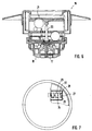
- FIG. 6 finally shows a volume measuring device in the form of a water meter 16.
- the structure of such a water meter is known, it is not in detail to go into more detail.
- the parts relevant to the present invention are Turned part in the form of an impeller 17, which by the lower part 18 of the Counter flowing water is rotated. The rotation is over a Magnetic coupling 19 transmitted to a rotary rod 20, which in turn is in motion coupling with a mechanical roller counter 21, on which see Fig. 7, the measured consumption is displayed.
- a rotary rod 20 which in turn is in motion coupling with a mechanical roller counter 21, on which see Fig. 7, the measured consumption is displayed.
- FIG. 7 is, is on the flat side surface 22 of the decadal roller 23, which here Representing rotary element, the partial surface 24 is applied.
- Assigned to the roll counter is the detection means 27 with the sensor element with the corresponding Printed circuit board 29 carrying electrodes 28.
- the voltage generating means and the evaluation means are not shown for reasons of clarity. In this way, the rotation of the roller 23 can be detected and accordingly the accumulated flow volume can be accumulated here. Via a corresponding Output not shown here, which is a can act electronic or an optical output, this can Value then electronically or optically tapped from the outside by means of a reading device become.
- the roller 23 is preferably the one-liter roller.
- FIGS. 8 and 9 show a second embodiment of a volume measuring device in the form of a water meter 30.
- This is also a mechanical one Counter provided, which on the one hand comprises a roller counter 31 and several pointers 32.
- the counters 32 or the entire counter are of a cap-like, usually made of transparent plastic Counter cover 33 overlapped.
- Pointer 32a is a separate one Unit 34 assigned, in which the sensor element 35 with the corresponding Electrodes 36 is integrated, furthermore the corresponding necessary detection means, which are not shown here for reasons of clarity.
- the electrically conductive partial surface 37 is scanned on the upper side of the pointer 32a is provided, through the counter cover 33, which acts as a dielectric layer within the coupling capacitors and an increase the same causes.
- the unit 34 itself can be detachable and in particular can be retrofitted attached to the volume measuring device, i.e. the volume measuring device is inherently with a counter 32a with the electrically conductive partial surface should then provide additional electronic functions such as radio transmission or the like can be realized on the device becomes easy the unit 34 is attached, which enables the volume detection and then in the additional components required for the desired electronic function, e.g. are integrated in the form of a radio device. Also not shown the corresponding safety equipment that prevents that unauthorized detachment of the unit 34 can occur, e.g. in the form of a seal or similar.
- FIG. 10 shows a further electrode configuration according to the invention. This exists from a central receiver electrode 38, which in the exemplary embodiment shown is circular. Arranged symmetrically around the receiver electrode 38 are four excitation electrodes 39a, 39b, 39c, 39d, each as circular ring segments are formed and cover a segment angle of 90 °. On each of the excitation electrodes 39a to 39d can be connected via suitable control lines a voltage pulse is applied to the receiver electrode, which is connected to a connected downstream amplifier, not shown, the corresponding Coupling signals tapped.
- the design is such that two electrodes opposite each other form a pair of electrodes, one of which acts as an excitation electrode, the other as Compensation electrode is used and an inverted voltage pulse is applied becomes.
- the excitation electrode 39a with a Voltage pulse with a positive edge at the same time the opposite excitation electrode 39c with an inverted voltage pulse of the same size with a negative one Edge driven.
- the resulting receiver electrode signal will tapped for this purpose and processed by the detection means. Then will a voltage pulse with a positive edge to the excitation electrode 39b and simultaneously a voltage pulse with a negative edge to the opposite excitation electrode 39d, and again the resulting receiver electrode signal tapped.
- the electrodes clearly show a sufficiently large area so that relative Coupling capacities are given, which lead to sufficiently high signals, what is advantageous in that it also changes in the distance between the Partial area, which is arranged, for example, in a water meter, and the electrodes, which, for example, on one for detection on the water meter housing attachable external device are arranged, easily compensated can, because even with a relatively large distance, sufficiently high signals can be tapped.
- Control also a sufficiently high modulation stroke, namely the between positive and negative coupling, in which the partial area is full over an excitation electrode with a positive edge or over an excitation electrode with a negative edge.
- FIG. 11 shows a rotary element 40 with an applied electrically conductive partial surface 41, for example a vapor-deposited metallization.
- a further smaller partial surface 42 is arranged on the large semicircular partial surface 41.
- the shape of this further partial area 42 preferably corresponds to the shape of the central receiver electrode 38. This realizes that the receiver electrode is always completely covered, half of which are covered by the further partial area 42, the other half of the electrode 38 by the partial area 41 the subareas 41, 42 are designed taking into account the size of the receiver electrode 38, possibly also that of the excitation electrodes 39a, 39d.
- the partial surface or the rotating element are preferably implemented in a planar manner.
- the excitation electrode 39a-39b or the diameter of the partial surface 41 should be chosen so that a complete overlap of two adjacent excitation electrodes is possible.
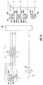
- Fig. 12 shows schematically the connection of an electrode configuration according to. 10 together with its control and an example of the signals tapped at the receiver electrode and located at the amplifier output.
- the receiver electrode 43 and the excitation electrodes 44a, 44b, 44c, 44d are not of circular or annular segment-like design, but rather polygonal. However, the symmetrical arrangement is still maintained.
- the excitation electrodes 44a-44d are subjected to voltage pulses via a detection means 45. On the basis of the voltage pulses I and II shown, it can be seen that, at time t 1 , the excitation electrode 44a and the opposite electrode 44c, which serves as the compensation electrode, are initially subjected to inverted voltage edges.
- the electrode 44a is acted upon with a positive pulse flank, the electrode 44c with a negative pulse flank.
- the signal that can be tapped at the receiver electrode 43 is amplified via an amplifier 46 and sent to the detection means 45.
- a voltage pulse II is given at the time t 2 , which is given to the excitation electrode 44b with its positive edge and to the excitation electrode 44d with its negative edge.
- a detector electrode signal is tapped by the detector means 45 via the analog comparator 46.
- the analog comparator detects the positive signals and outputs corresponding logic signals.
- FIG. 12 also shows the taps that can be tapped at the output of the analog comparator 46 Signals are given to different positions of the partial area. Because the analog comparator if only positive signals are detected, the detection means are only positive or no signals.
- the conductive partial surface covers the two Electrodes 44a, 44b. Both are driven with positive voltage edges, so that two positive receiver signals are added to the two pulses I, II become.
- the partial surface 47 continues to rotate and covers the electrodes 44b, 44c. Due to the control of the electrode 44c with the negative inverted edge there is no signal for pulse I, but a pulse for pulse II positive, since the electrode 44b is driven with the positive edge.
- the partial surface 47 covers the electrodes 44c, 44d. Because of their control with the respective negative edge are no signals to the Get pulses I, II. In case D the electrodes 44d, 44a are covered, which due to the control leads to a positive signal to pulse I, to pulse II there is no signal at the detection means. Due to the receiver signals or Signal distribution to the respective pulses, it is possible that the detection means 45 already from the receiver signals that are determined in cases A and B, can determine direction detection.
- the respective signals for the pulses As described, I, II have certain polarities, the quadrature direction detection enable.
- the two received in the respective overlap case Signals each form the usual two-bit quadrature signal for direction detection.
- each of the electrodes 44a-44d is in a very rapid sequence real "excitation electrode with a positive voltage pulse and the respective counterpart is acted upon with a negative voltage pulse.
- This mode of operation is carried out, for example, at certain time intervals and is used to determine whether a conductive partial surface is actually facing in any position or not. This is to avoid manipulation 12.
- electrodes 44a and 44c are first driven with a positive or negative voltage edge and the associated signal is tapped at receiver electrode 43. The drive pulse is present until time t 3 and then drops to zero.
- the excitation electrode 44b with the positive edge, the excitation electrode 44d is applied with the negative edge, and this drive pulse is up to the time t 4 and then drops to zero.
- These flanks are given by the falling pulse that has been present since t 1 .
- the excitation electrode 44 d is acted upon by the positive and the electrode 44b by the negative flank.
- the flanks are generated by the pulse that has been present since time t 2 . This sequential pulse build-up takes place very quickly, it takes place within a period of time that is significantly less than the minimum revolution time of the partial area.
- the electrodes are 44a, 44b coupled. Both become signal pulses I and II applied to the positive edge so that two positive signals are tapped. However, negative pulses are applied to pulses III and IV, so that there are no signals at the detection means. Become visible ie receive different signals if a conductive partial surface is opposite. In the event that there would be no such, there would be no capacitive Given electrode coupling, so that no signal pulse is obtained overall. In the event that this is detected, it is clearly recognizable that no conductive Partial area faces, therefore no encoder element at the time of recording and therefore no water meter is within range of the electrodes. Even in the event that the partial surface position deviates from the idealized position and the electrodes are only partially covered, which is usually the case Despite everything, there are always different areas Receiver signals.
- control examples described are only exemplary. Of course there is the possibility of the processes and signals also with reverse polarity of the drive and accordingly to realize the detection signals.
Landscapes
- Physics & Mathematics (AREA)
- General Physics & Mathematics (AREA)
- Transmission And Conversion Of Sensor Element Output (AREA)
- Indicating Or Recording The Presence, Absence, Or Direction Of Movement (AREA)
- Exhaust Gas Treatment By Means Of Catalyst (AREA)
- Electrostatic Spraying Apparatus (AREA)
- Filtering Of Dispersed Particles In Gases (AREA)
- Details Of Flowmeters (AREA)
- Measuring Volume Flow (AREA)
- Rotational Drive Of Disk (AREA)
- Investigating Or Analyzing Materials By The Use Of Electric Means (AREA)
Applications Claiming Priority (2)
| Application Number | Priority Date | Filing Date | Title |
|---|---|---|---|
| DE19908612 | 1999-02-27 | ||
| DE19908612A DE19908612B4 (de) | 1999-02-27 | 1999-02-27 | Anordnung zum Detektieren einer Rotation eines Drehelements |
Publications (3)
| Publication Number | Publication Date |
|---|---|
| EP1033578A2 true EP1033578A2 (fr) | 2000-09-06 |
| EP1033578A3 EP1033578A3 (fr) | 2000-11-02 |
| EP1033578B1 EP1033578B1 (fr) | 2005-04-06 |
Family
ID=7899128
Family Applications (1)
| Application Number | Title | Priority Date | Filing Date |
|---|---|---|---|
| EP00102683A Expired - Lifetime EP1033578B1 (fr) | 1999-02-27 | 2000-02-09 | Dispositif de détermination de la rotation d'un élément rotatif |
Country Status (6)
| Country | Link |
|---|---|
| EP (1) | EP1033578B1 (fr) |
| AT (1) | ATE292803T1 (fr) |
| DE (2) | DE19908612B4 (fr) |
| HU (1) | HUP0000749A3 (fr) |
| PL (1) | PL338627A1 (fr) |
| SK (1) | SK2112000A3 (fr) |
Cited By (7)
| Publication number | Priority date | Publication date | Assignee | Title |
|---|---|---|---|---|
| FR2849186A1 (fr) * | 2002-12-23 | 2004-06-25 | Actaris Sas | Dispositif de detection du positionnement d'un module de mesure sur un compteur de fluide |
| EP1785732A1 (fr) * | 2005-11-11 | 2007-05-16 | Prof. Dr. Horst Ziegler und Partner GbR | Dispositif pour la détection de la rotation d'un élément rotatif |
| EP2108963A2 (fr) | 2008-04-09 | 2009-10-14 | Prof. Dr. Horst Ziegler und Partner GbR | Dispositif de détection d'une rotation d'un élément rotatif |
| WO2010000861A1 (fr) * | 2008-07-04 | 2010-01-07 | Ident Technology Ag | Dispositif capteur capacitif |
| WO2012107415A1 (fr) | 2011-02-07 | 2012-08-16 | Ident Technology Ag | Configuration d'électrodes pour un dispositif capteur capacitif, ainsi que dispositif capteur capacitif pour la détection d'une approximation |
| DE102016204439A1 (de) | 2016-03-17 | 2017-09-21 | Hochschule Karlsruhe-Technik Und Wirtschaft | Kapazitiver Winkelsensor |
| CN109945931A (zh) * | 2019-04-23 | 2019-06-28 | 宁波水表股份有限公司 | 计量装置和计量仪 |
Families Citing this family (7)
| Publication number | Priority date | Publication date | Assignee | Title |
|---|---|---|---|---|
| DE10027647B4 (de) * | 2000-06-03 | 2004-02-05 | Hydrometer Gmbh | Anordnung zum Detektieren einer Rotation eines Drehelements |
| DE10060198A1 (de) * | 2000-12-01 | 2002-06-13 | Abb Patent Gmbh | Impulsgebereinrichtung für Volumenzähler |
| DE102007006607B4 (de) * | 2007-02-10 | 2010-08-05 | Techem Energy Services Gmbh | Modul zur kapazitiven Abtastung und Verbrauchszähler |
| DE102008039377A1 (de) | 2008-08-22 | 2010-02-25 | Hengstler Gmbh | Vorrichtung zur Abtastung der Teilstriche eines mechanischen Rollenzählwerks bei Zählern aller Art |
| DE102009052537B4 (de) * | 2009-11-11 | 2011-12-22 | Ident Technology Ag | Sensorelektronik für eine Mehrzahl von Sensorelementen sowie Verfahren zum Bestimmen einer Position eines Objektes an den Sensorelementen |
| DE102010018271B4 (de) | 2010-04-26 | 2012-12-20 | Prof. Dr. Horst Ziegler & Partner GbR (vertretungsberechtigter Gesellschafter: Dipl.-Ing. F. W. Ziegler, 70499 Stuttgart) | Technik zur Erfassung einer Drehbewegung |
| DE102011015589B3 (de) | 2011-03-30 | 2012-04-12 | Techem Energy Services Gmbh | Anordnung und Verfahren zur kapazitiven Abtastung der Drehbwegung eines Drehelements |
Citations (14)
| Publication number | Priority date | Publication date | Assignee | Title |
|---|---|---|---|---|
| DE1774578A1 (de) * | 1968-07-19 | 1972-02-03 | Bopp & Reuther Gmbh | Fernuebertragung von Messergebnissen,insbesondere bei Fluessigkeitszaehlern |
| US3766544A (en) * | 1971-11-19 | 1973-10-16 | Northern Illinois Gas Co | Analog-to-digital converter employing electrostatic signal coupling apparatus |
| DE2748425A1 (de) * | 1976-10-29 | 1978-05-03 | Elin Union Ag | Einrichtung zur beruehrungslosen abtastung von bewegungsvorgaengen |
| US4391144A (en) * | 1979-03-12 | 1983-07-05 | Krautkramer-Branson, Inc. | Ultrasonic test probe |
| US4488152A (en) * | 1982-02-01 | 1984-12-11 | Schlumberger Canada Limited | Register position sensing and controlling apparatus |
| DE3340508A1 (de) * | 1983-11-09 | 1985-11-07 | Bopp & Reuther Gmbh, 6800 Mannheim | Impulsgebereinrichtung fuer wasserzaehler |
| US4556864A (en) * | 1982-08-26 | 1985-12-03 | Roy Joseph J | Apparatus and method for communicating digital information on AC power lines |
| US4779094A (en) * | 1985-11-23 | 1988-10-18 | Lee Doo S | Apparatus for remotely determining the angular orientation, speed and/or direction of rotary objects |
| DE3711062A1 (de) * | 1987-04-02 | 1988-10-20 | Herbert Leypold | Kapazitive absolute positionsmessvorrichtung |
| US4843387A (en) * | 1985-05-23 | 1989-06-27 | Mitutoyo Mfg. Co., Ltd. | Variable capacitance type encoder |
| US4924407A (en) * | 1988-08-15 | 1990-05-08 | Siecor Corporation | Humidity resistant meter reading device |
| EP0397335A2 (fr) * | 1989-05-09 | 1990-11-14 | Advanced Micro Devices, Inc. | Translateur de niveaux logiques de type CMOS |
| US5077635A (en) * | 1990-05-22 | 1991-12-31 | Robert Bosch Gmbh | Capacitive position sensor |
| EP0701109A2 (fr) * | 1994-08-16 | 1996-03-13 | Hydrometer Gesellschaft mbH | Compteur d'eau |
Family Cites Families (4)
| Publication number | Priority date | Publication date | Assignee | Title |
|---|---|---|---|---|
| AT389006B (de) * | 1979-06-06 | 1989-10-10 | Elin Wasserwerkstechnik Ges Mb | Anordnung zur beruehrungslosen kapazitiven erfassung von drehbewegungen |
| GB2096328A (en) * | 1981-04-06 | 1982-10-13 | Schlumberger Ca Ltd | Apparatus for electrically measuring rotation |
| CH664019A5 (de) * | 1983-09-15 | 1988-01-29 | Zellweger Uster Ag | Einrichtung zur zaehlung der umdrehungen einer laeuferscheibe eines elektrizitaetszaehlers. |
| DE3429326A1 (de) * | 1984-08-09 | 1986-02-13 | Engelmann, Hans, 6908 Wiesloch | Vorrichtung zur messung der drehzahl und gegebenenfalls der drehrichtung eines fluegelrades eines fluegelraddurchflussmessers in stroemenden fluessigkeiten |
-
1999
- 1999-02-27 DE DE19908612A patent/DE19908612B4/de not_active Expired - Fee Related
-
2000
- 2000-02-09 DE DE50009954T patent/DE50009954D1/de not_active Expired - Lifetime
- 2000-02-09 AT AT00102683T patent/ATE292803T1/de active
- 2000-02-09 EP EP00102683A patent/EP1033578B1/fr not_active Expired - Lifetime
- 2000-02-16 SK SK211-2000A patent/SK2112000A3/sk unknown
- 2000-02-21 HU HU0000749A patent/HUP0000749A3/hu unknown
- 2000-02-25 PL PL00338627A patent/PL338627A1/xx not_active Application Discontinuation
Patent Citations (14)
| Publication number | Priority date | Publication date | Assignee | Title |
|---|---|---|---|---|
| DE1774578A1 (de) * | 1968-07-19 | 1972-02-03 | Bopp & Reuther Gmbh | Fernuebertragung von Messergebnissen,insbesondere bei Fluessigkeitszaehlern |
| US3766544A (en) * | 1971-11-19 | 1973-10-16 | Northern Illinois Gas Co | Analog-to-digital converter employing electrostatic signal coupling apparatus |
| DE2748425A1 (de) * | 1976-10-29 | 1978-05-03 | Elin Union Ag | Einrichtung zur beruehrungslosen abtastung von bewegungsvorgaengen |
| US4391144A (en) * | 1979-03-12 | 1983-07-05 | Krautkramer-Branson, Inc. | Ultrasonic test probe |
| US4488152A (en) * | 1982-02-01 | 1984-12-11 | Schlumberger Canada Limited | Register position sensing and controlling apparatus |
| US4556864A (en) * | 1982-08-26 | 1985-12-03 | Roy Joseph J | Apparatus and method for communicating digital information on AC power lines |
| DE3340508A1 (de) * | 1983-11-09 | 1985-11-07 | Bopp & Reuther Gmbh, 6800 Mannheim | Impulsgebereinrichtung fuer wasserzaehler |
| US4843387A (en) * | 1985-05-23 | 1989-06-27 | Mitutoyo Mfg. Co., Ltd. | Variable capacitance type encoder |
| US4779094A (en) * | 1985-11-23 | 1988-10-18 | Lee Doo S | Apparatus for remotely determining the angular orientation, speed and/or direction of rotary objects |
| DE3711062A1 (de) * | 1987-04-02 | 1988-10-20 | Herbert Leypold | Kapazitive absolute positionsmessvorrichtung |
| US4924407A (en) * | 1988-08-15 | 1990-05-08 | Siecor Corporation | Humidity resistant meter reading device |
| EP0397335A2 (fr) * | 1989-05-09 | 1990-11-14 | Advanced Micro Devices, Inc. | Translateur de niveaux logiques de type CMOS |
| US5077635A (en) * | 1990-05-22 | 1991-12-31 | Robert Bosch Gmbh | Capacitive position sensor |
| EP0701109A2 (fr) * | 1994-08-16 | 1996-03-13 | Hydrometer Gesellschaft mbH | Compteur d'eau |
Non-Patent Citations (1)
| Title |
|---|
| FABIAN T ET AL: "A ROBUST CAPACITIVE ANGULAR SPEED SENSOR" , INSTRUMENTATION AND MEASUREMENT TECHNOLOGY CONFERENCE PROCEEDINGS. (IMTC),US,NEW YORK, IEEE, VOL. CONF. 14, PAGE(S) 1267-1272 XP000730879ISBN: 0-7803-3748-4 * das ganze Dokument * * |
Cited By (13)
| Publication number | Priority date | Publication date | Assignee | Title |
|---|---|---|---|---|
| FR2849186A1 (fr) * | 2002-12-23 | 2004-06-25 | Actaris Sas | Dispositif de detection du positionnement d'un module de mesure sur un compteur de fluide |
| EP1434038A2 (fr) * | 2002-12-23 | 2004-06-30 | Actaris S.A.S. | Dispositif de détection du positionnement d'un module de mesure sur un compteur de fluide |
| EP1434038A3 (fr) * | 2002-12-23 | 2006-05-03 | Actaris S.A.S. | Dispositif de détection du positionnement d'un module de mesure sur un compteur de fluide |
| EP1785732A1 (fr) * | 2005-11-11 | 2007-05-16 | Prof. Dr. Horst Ziegler und Partner GbR | Dispositif pour la détection de la rotation d'un élément rotatif |
| EP2108963A2 (fr) | 2008-04-09 | 2009-10-14 | Prof. Dr. Horst Ziegler und Partner GbR | Dispositif de détection d'une rotation d'un élément rotatif |
| DE102008018099A1 (de) | 2008-04-09 | 2009-11-05 | Prof. Dr. Horst Ziegler und Partner GbR (vertretungsberechtigter Gesellschafter: Prof. Dr. Horst Ziegler 33100 Paderborn) | Anordnung zum Erfassen einer Drehung eines Drehelements |
| WO2010000861A1 (fr) * | 2008-07-04 | 2010-01-07 | Ident Technology Ag | Dispositif capteur capacitif |
| US9074310B2 (en) | 2008-07-04 | 2015-07-07 | Ident Technology Ag | Capacitative sensor device |
| WO2012107415A1 (fr) | 2011-02-07 | 2012-08-16 | Ident Technology Ag | Configuration d'électrodes pour un dispositif capteur capacitif, ainsi que dispositif capteur capacitif pour la détection d'une approximation |
| KR20140052962A (ko) * | 2011-02-07 | 2014-05-07 | 마이크로칩 테크놀로지 저머니 Ⅱ 게엠베하 운트 콤파니 카게 | 정전용량성 센서 디바이스용 전극 구조 및 접근 검출용 정전용량성 센서 디바이스 |
| US9989569B2 (en) | 2011-02-07 | 2018-06-05 | Microchip Technology Germany Gmbh | Electrode configuration for a capacitive sensor device and a capacitive sensor device for the detection of an approximation |
| DE102016204439A1 (de) | 2016-03-17 | 2017-09-21 | Hochschule Karlsruhe-Technik Und Wirtschaft | Kapazitiver Winkelsensor |
| CN109945931A (zh) * | 2019-04-23 | 2019-06-28 | 宁波水表股份有限公司 | 计量装置和计量仪 |
Also Published As
| Publication number | Publication date |
|---|---|
| DE19908612A1 (de) | 2000-09-14 |
| EP1033578B1 (fr) | 2005-04-06 |
| SK2112000A3 (en) | 2000-09-12 |
| EP1033578A3 (fr) | 2000-11-02 |
| ATE292803T1 (de) | 2005-04-15 |
| HU0000749D0 (en) | 2000-04-28 |
| HUP0000749A3 (en) | 2002-10-28 |
| DE19908612B4 (de) | 2004-06-03 |
| DE50009954D1 (de) | 2005-05-12 |
| PL338627A1 (en) | 2000-08-28 |
| HUP0000749A2 (hu) | 2000-09-28 |
Similar Documents
| Publication | Publication Date | Title |
|---|---|---|
| EP1785732B1 (fr) | Dispositif pour la détection de la rotation d'un élément rotatif | |
| EP1033578B1 (fr) | Dispositif de détermination de la rotation d'un élément rotatif | |
| EP2965043B1 (fr) | Codeur linéaire ou rotatif magnétique | |
| EP1565755B2 (fr) | Detecteur de position | |
| DE4141959A1 (de) | Drehzahlsensor, insbesondere zahnradsensor | |
| DE102008015837A1 (de) | Positionsmessgerät und Verfahren zu dessen Betrieb | |
| WO1998008060A1 (fr) | Dispositif de detection sans contact d'un angle de rotation | |
| DE102005008484A1 (de) | Drehwinkelsensor | |
| DE102004057909A1 (de) | Linearer Positionssensor | |
| EP2691743B1 (fr) | Agencement et procédé de détection capacitive du mouvement de rotation d'un élément rotatif. | |
| DE102008027921B4 (de) | Admittanzmeßvorrichtung für einen Füllstandsensor | |
| DE102013103445A1 (de) | Magnetischer Linear- oder Drehgeber | |
| EP1510787B1 (fr) | Procédé et capteur angulaire de mesure de la position angulaire absolue | |
| EP0264408A1 (fr) | Detecteur de proximite par induction | |
| DE3804786C2 (fr) | ||
| EP0836072B1 (fr) | Capteur de rotation | |
| DE102013102543B4 (de) | Drehgeber mit geringer Leistungsaufnahme | |
| WO2010020413A1 (fr) | Dispositif de balayage inductif des traits de graduation d'une minuterie mécanique à rouleaux, sur des compteurs de tout type | |
| DE102008018099A1 (de) | Anordnung zum Erfassen einer Drehung eines Drehelements | |
| EP1391735B1 (fr) | Circuit d'évaluation pour des capteurs à circuit oscillant | |
| DE10354469B4 (de) | Vorrichtung zum Messen des Drehwinkels eines Drehkörpers | |
| DE3429326C2 (fr) | ||
| DE3422172C2 (fr) | ||
| EP1506378B1 (fr) | Procede de mesure d'une substance s'ecoulant dans un tuyau de mesure | |
| EP0807806A2 (fr) | Circuit de détection de rayonnement électromagnétique |
Legal Events
| Date | Code | Title | Description |
|---|---|---|---|
| PUAI | Public reference made under article 153(3) epc to a published international application that has entered the european phase |
Free format text: ORIGINAL CODE: 0009012 |
|
| AK | Designated contracting states |
Kind code of ref document: A2 Designated state(s): AT BE CH CY DE DK ES FI FR GB GR IE IT LI LU MC NL PT SE |
|
| AX | Request for extension of the european patent |
Free format text: AL;LT;LV;MK;RO;SI |
|
| PUAL | Search report despatched |
Free format text: ORIGINAL CODE: 0009013 |
|
| AK | Designated contracting states |
Kind code of ref document: A3 Designated state(s): AT BE CH CY DE DK ES FI FR GB GR IE IT LI LU MC NL PT SE |
|
| AX | Request for extension of the european patent |
Free format text: AL;LT;LV;MK;RO;SI |
|
| RIC1 | Information provided on ipc code assigned before grant |
Free format text: 7G 01P 3/483 A, 7G 01D 5/241 B, 7G 01P 13/04 B, 7G 01F 15/06 B |
|
| 17P | Request for examination filed |
Effective date: 20001121 |
|
| AKX | Designation fees paid |
Free format text: AT BE CH CY DE DK ES FI FR GB GR IE IT LI LU MC NL PT SE |
|
| AXX | Extension fees paid |
Free format text: SI PAYMENT 20001121 |
|
| 17Q | First examination report despatched |
Effective date: 20030616 |
|
| GRAP | Despatch of communication of intention to grant a patent |
Free format text: ORIGINAL CODE: EPIDOSNIGR1 |
|
| GRAS | Grant fee paid |
Free format text: ORIGINAL CODE: EPIDOSNIGR3 |
|
| GRAA | (expected) grant |
Free format text: ORIGINAL CODE: 0009210 |
|
| AK | Designated contracting states |
Kind code of ref document: B1 Designated state(s): AT BE CH CY DE DK ES FI FR GB GR IE IT LI LU MC NL PT SE |
|
| AX | Request for extension of the european patent |
Extension state: SI |
|
| PG25 | Lapsed in a contracting state [announced via postgrant information from national office to epo] |
Ref country code: IT Free format text: LAPSE BECAUSE OF FAILURE TO SUBMIT A TRANSLATION OF THE DESCRIPTION OR TO PAY THE FEE WITHIN THE PRE;WARNING: LAPSES OF ITALIAN PATENTS WITH EFFECTIVE DATE BEFORE 2007 MAY HAVE OCCURRED AT ANY TIME BEFORE 2007. THE CORRECT EFFECTIVE DATE MAY BE DIFFERENT FROM THE ONE RECORDED.SCRIBED TIME-LIMIT Effective date: 20050406 Ref country code: FI Free format text: LAPSE BECAUSE OF FAILURE TO SUBMIT A TRANSLATION OF THE DESCRIPTION OR TO PAY THE FEE WITHIN THE PRESCRIBED TIME-LIMIT Effective date: 20050406 Ref country code: GB Free format text: LAPSE BECAUSE OF FAILURE TO SUBMIT A TRANSLATION OF THE DESCRIPTION OR TO PAY THE FEE WITHIN THE PRESCRIBED TIME-LIMIT Effective date: 20050406 Ref country code: IE Free format text: LAPSE BECAUSE OF FAILURE TO SUBMIT A TRANSLATION OF THE DESCRIPTION OR TO PAY THE FEE WITHIN THE PRESCRIBED TIME-LIMIT Effective date: 20050406 Ref country code: NL Free format text: LAPSE BECAUSE OF FAILURE TO SUBMIT A TRANSLATION OF THE DESCRIPTION OR TO PAY THE FEE WITHIN THE PRESCRIBED TIME-LIMIT Effective date: 20050406 |
|
| REG | Reference to a national code |
Ref country code: GB Ref legal event code: FG4D Free format text: NOT ENGLISH |
|
| REG | Reference to a national code |
Ref country code: CH Ref legal event code: NV Representative=s name: ISLER & PEDRAZZINI AG Ref country code: CH Ref legal event code: EP |
|
| REG | Reference to a national code |
Ref country code: IE Ref legal event code: FG4D Free format text: LANGUAGE OF EP DOCUMENT: GERMAN |
|
| REF | Corresponds to: |
Ref document number: 50009954 Country of ref document: DE Date of ref document: 20050512 Kind code of ref document: P |
|
| PG25 | Lapsed in a contracting state [announced via postgrant information from national office to epo] |
Ref country code: DK Free format text: LAPSE BECAUSE OF FAILURE TO SUBMIT A TRANSLATION OF THE DESCRIPTION OR TO PAY THE FEE WITHIN THE PRESCRIBED TIME-LIMIT Effective date: 20050706 Ref country code: SE Free format text: LAPSE BECAUSE OF FAILURE TO SUBMIT A TRANSLATION OF THE DESCRIPTION OR TO PAY THE FEE WITHIN THE PRESCRIBED TIME-LIMIT Effective date: 20050706 Ref country code: GR Free format text: LAPSE BECAUSE OF FAILURE TO SUBMIT A TRANSLATION OF THE DESCRIPTION OR TO PAY THE FEE WITHIN THE PRESCRIBED TIME-LIMIT Effective date: 20050706 |
|
| PG25 | Lapsed in a contracting state [announced via postgrant information from national office to epo] |
Ref country code: ES Free format text: LAPSE BECAUSE OF FAILURE TO SUBMIT A TRANSLATION OF THE DESCRIPTION OR TO PAY THE FEE WITHIN THE PRESCRIBED TIME-LIMIT Effective date: 20050717 |
|
| PG25 | Lapsed in a contracting state [announced via postgrant information from national office to epo] |
Ref country code: PT Free format text: LAPSE BECAUSE OF FAILURE TO SUBMIT A TRANSLATION OF THE DESCRIPTION OR TO PAY THE FEE WITHIN THE PRESCRIBED TIME-LIMIT Effective date: 20050908 |
|
| NLV1 | Nl: lapsed or annulled due to failure to fulfill the requirements of art. 29p and 29m of the patents act | ||
| GBV | Gb: ep patent (uk) treated as always having been void in accordance with gb section 77(7)/1977 [no translation filed] |
Effective date: 20050406 |
|
| REG | Reference to a national code |
Ref country code: IE Ref legal event code: FD4D |
|
| PLBE | No opposition filed within time limit |
Free format text: ORIGINAL CODE: 0009261 |
|
| STAA | Information on the status of an ep patent application or granted ep patent |
Free format text: STATUS: NO OPPOSITION FILED WITHIN TIME LIMIT |
|
| PG25 | Lapsed in a contracting state [announced via postgrant information from national office to epo] |
Ref country code: LU Free format text: LAPSE BECAUSE OF NON-PAYMENT OF DUE FEES Effective date: 20060228 Ref country code: BE Free format text: LAPSE BECAUSE OF NON-PAYMENT OF DUE FEES Effective date: 20060228 Ref country code: MC Free format text: LAPSE BECAUSE OF NON-PAYMENT OF DUE FEES Effective date: 20060228 |
|
| ET | Fr: translation filed | ||
| 26N | No opposition filed |
Effective date: 20060110 |
|
| REG | Reference to a national code |
Ref country code: CH Ref legal event code: PCAR Free format text: ISLER & PEDRAZZINI AG;POSTFACH 1772;8027 ZUERICH (CH) |
|
| BERE | Be: lapsed |
Owner name: ZIEGLER, HORST PROF. DR. Effective date: 20060228 |
|
| PG25 | Lapsed in a contracting state [announced via postgrant information from national office to epo] |
Ref country code: CY Free format text: LAPSE BECAUSE OF FAILURE TO SUBMIT A TRANSLATION OF THE DESCRIPTION OR TO PAY THE FEE WITHIN THE PRESCRIBED TIME-LIMIT Effective date: 20050406 |
|
| REG | Reference to a national code |
Ref country code: FR Ref legal event code: PLFP Year of fee payment: 17 |
|
| REG | Reference to a national code |
Ref country code: FR Ref legal event code: PLFP Year of fee payment: 18 |
|
| PGFP | Annual fee paid to national office [announced via postgrant information from national office to epo] |
Ref country code: CH Payment date: 20170221 Year of fee payment: 18 Ref country code: DE Payment date: 20170215 Year of fee payment: 18 Ref country code: FR Payment date: 20170220 Year of fee payment: 18 |
|
| PGFP | Annual fee paid to national office [announced via postgrant information from national office to epo] |
Ref country code: AT Payment date: 20170217 Year of fee payment: 18 |
|
| REG | Reference to a national code |
Ref country code: DE Ref legal event code: R119 Ref document number: 50009954 Country of ref document: DE |
|
| REG | Reference to a national code |
Ref country code: CH Ref legal event code: PL |
|
| REG | Reference to a national code |
Ref country code: AT Ref legal event code: MM01 Ref document number: 292803 Country of ref document: AT Kind code of ref document: T Effective date: 20180209 |
|
| PG25 | Lapsed in a contracting state [announced via postgrant information from national office to epo] |
Ref country code: LI Free format text: LAPSE BECAUSE OF NON-PAYMENT OF DUE FEES Effective date: 20180228 Ref country code: CH Free format text: LAPSE BECAUSE OF NON-PAYMENT OF DUE FEES Effective date: 20180228 Ref country code: AT Free format text: LAPSE BECAUSE OF NON-PAYMENT OF DUE FEES Effective date: 20180209 |
|
| REG | Reference to a national code |
Ref country code: FR Ref legal event code: ST Effective date: 20181031 |
|
| PG25 | Lapsed in a contracting state [announced via postgrant information from national office to epo] |
Ref country code: DE Free format text: LAPSE BECAUSE OF NON-PAYMENT OF DUE FEES Effective date: 20180901 |
|
| PG25 | Lapsed in a contracting state [announced via postgrant information from national office to epo] |
Ref country code: FR Free format text: LAPSE BECAUSE OF NON-PAYMENT OF DUE FEES Effective date: 20180228 |