EP1033490A2 - Control valve for variable displacement compressor - Google Patents
Control valve for variable displacement compressor Download PDFInfo
- Publication number
- EP1033490A2 EP1033490A2 EP00104151A EP00104151A EP1033490A2 EP 1033490 A2 EP1033490 A2 EP 1033490A2 EP 00104151 A EP00104151 A EP 00104151A EP 00104151 A EP00104151 A EP 00104151A EP 1033490 A2 EP1033490 A2 EP 1033490A2
- Authority
- EP
- European Patent Office
- Prior art keywords
- pressure
- chamber
- control valve
- actuator
- rod
- Prior art date
- Legal status (The legal status is an assumption and is not a legal conclusion. Google has not performed a legal analysis and makes no representation as to the accuracy of the status listed.)
- Withdrawn
Links
Images

Classifications
-
- F—MECHANICAL ENGINEERING; LIGHTING; HEATING; WEAPONS; BLASTING
- F04—POSITIVE - DISPLACEMENT MACHINES FOR LIQUIDS; PUMPS FOR LIQUIDS OR ELASTIC FLUIDS
- F04B—POSITIVE-DISPLACEMENT MACHINES FOR LIQUIDS; PUMPS
- F04B27/00—Multi-cylinder pumps specially adapted for elastic fluids and characterised by number or arrangement of cylinders
- F04B27/08—Multi-cylinder pumps specially adapted for elastic fluids and characterised by number or arrangement of cylinders having cylinders coaxial with, or parallel or inclined to, main shaft axis
- F04B27/14—Control
- F04B27/16—Control of pumps with stationary cylinders
- F04B27/18—Control of pumps with stationary cylinders by varying the relative positions of a swash plate and a cylinder block
- F04B27/1804—Controlled by crankcase pressure
- F04B2027/1809—Controlled pressure
- F04B2027/1813—Crankcase pressure
-
- F—MECHANICAL ENGINEERING; LIGHTING; HEATING; WEAPONS; BLASTING
- F04—POSITIVE - DISPLACEMENT MACHINES FOR LIQUIDS; PUMPS FOR LIQUIDS OR ELASTIC FLUIDS
- F04B—POSITIVE-DISPLACEMENT MACHINES FOR LIQUIDS; PUMPS
- F04B27/00—Multi-cylinder pumps specially adapted for elastic fluids and characterised by number or arrangement of cylinders
- F04B27/08—Multi-cylinder pumps specially adapted for elastic fluids and characterised by number or arrangement of cylinders having cylinders coaxial with, or parallel or inclined to, main shaft axis
- F04B27/14—Control
- F04B27/16—Control of pumps with stationary cylinders
- F04B27/18—Control of pumps with stationary cylinders by varying the relative positions of a swash plate and a cylinder block
- F04B27/1804—Controlled by crankcase pressure
- F04B2027/1822—Valve-controlled fluid connection
- F04B2027/1831—Valve-controlled fluid connection between crankcase and suction chamber
-
- F—MECHANICAL ENGINEERING; LIGHTING; HEATING; WEAPONS; BLASTING
- F04—POSITIVE - DISPLACEMENT MACHINES FOR LIQUIDS; PUMPS FOR LIQUIDS OR ELASTIC FLUIDS
- F04B—POSITIVE-DISPLACEMENT MACHINES FOR LIQUIDS; PUMPS
- F04B27/00—Multi-cylinder pumps specially adapted for elastic fluids and characterised by number or arrangement of cylinders
- F04B27/08—Multi-cylinder pumps specially adapted for elastic fluids and characterised by number or arrangement of cylinders having cylinders coaxial with, or parallel or inclined to, main shaft axis
- F04B27/14—Control
- F04B27/16—Control of pumps with stationary cylinders
- F04B27/18—Control of pumps with stationary cylinders by varying the relative positions of a swash plate and a cylinder block
- F04B27/1804—Controlled by crankcase pressure
- F04B2027/184—Valve controlling parameter
- F04B2027/185—Discharge pressure
Definitions
- the present invention relates to control valves for variable displacement compressors, which vary the amount of discharge of compressors by controlling the amount of gas discharged from a crank chamber of a variable displacement compressor.
- Variable displacement compressors which vary displacement by controlling the inclination angle of tiltable swash plates disposed in a crank chamber within a compressor, are well known as compressors used in automobile air conditioners.
- the inclination angle of the swash plate is regulated by controlling the pressure of the gas (crank pressure Pc) in the crank chamber using a special valve.
- outlet control One method to control the crank pressure is called outlet control. This type of control method regulates the crank pressure by controlling the amount of gas discharged from the crank chamber using an outlet control valve located within a bleed passage that links the crank chamber and the suction chamber. Additionally, the suction chamber of the compressor is connected to the outlet of an evaporator of an external refrigerant circuit.
- a pressure sensitive member deforms in response to changes in the pressure (suction pressure Ps) at the suction chamber, which corresponds to the pressure at the outlet of the evaporator. This in turn actuates the valve body.
- a target value is set in advance for the suction pressure (target suction pressure) depending on the amount of force applied to the pressure sensitive member.
- the control valve automatically controls the opening of the valve body such that the suction pressure Ps converges on the target suction pressure.
- discharge pressure Pd discharge pressure
- suction pressure Ps becomes higher than the pressure Ps' at the outlet of the evaporator as the discharge pressure Pd increases.
- the control valve uses the suction pressure Ps as the pressure Ps' at the outlet of the evaporator. Consequently, it becomes impossible for the difference between both pressures Ps and Ps' to accurately control pressure Ps' at the outlet of the evaporator.
- a control valve disclosed in Japanese Unexamined Patent Publication No. 5-52182 includes a diaphragm (pressure sensitive member) that deforms in response to suction pressure changes, a spherical valve body actuated by means of the diaphragm, and a rod that transmits the displacement of the diaphragm to the valve body.
- a pressure correction mechanism is located between the diaphragm and the valve body to compensate for differences between the suction pressure and the pressure at the outlet of the evaporator. This pressure correction mechanism has a chamber where discharge pressure is introduced and the rod passes through the chamber.
- valve body in the control valve of Japanese Unexamined Patent Publication No. 5-52182 is spherical, the valve body and the rod must be produced separately making the production of the control valve complicated. Further, the action of placing the valve body at established locations within the control valve and the action of placing the rod such that it passes through the chamber of the pressure correction mechanism must be carried out separately, making the assembly of the control valve tedious.
- the present invention provides a control valve for a variable displacement compressor.
- the control, valve adjusts the pressure of a crank chamber in the compressor to vary the compressor displacement.
- the compressor includes a suction pressure region to which suction pressure is communicated, a discharge pressure region to which a discharge pressure is communicated, and a bleed passage connecting the crank chamber to the suction pressure region.
- the control valve includes a housing, a pressure sensitive member arranged in the housing to deform in accordance with the suction pressure, and an actuator extending from the pressure sensitive member and arranged in the housing.
- the actuator includes a valve body for adjusting the opened amount of the bleed passage and a pressure receiving body for receiving the discharge pressure.
- the pressure sensitive member drives the valve body in accordance with the suction pressure.
- the pressure receiving body urges the pressure sensitive member in a single direction with a force corresponding to the discharge pressure, and the actuator is formed so that its cross-sectional area decreases in a stepped manner axially.
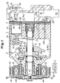
- variable displacement type swash plate compressor includes a cylinder block 1, a front housing member 2 joined to the front end of the cylinder block 1, and a rear housing member 4 joined to the rear end of the cylinder block 1 through a valve plate 3.
- the cylinder block 1, front housing member 2, valve plate 3 and rear housing member 4 are held together with a plurality of bolts (not shown) to form the compressor housing.
- a crank chamber 5 is defined between the cylinder block 1 and the front housing member 2.
- a drive shaft 6 is supported by the cylinder block 1 and the front housing member 2 with a plurality of radial bearings.
- a bore housing a helical spring 7 and a thrust bearing 8 is formed substantially at the center of the cylinder block 1.
- a rotating support 11 is fixed on the drive shaft 6 to rotate integrally with the drive shaft 6.
- Another thrust bearing 9 is located between the rotating support 11 and an inner wall of the front housing member 2.
- the drive shaft 6 is supported in the axial direction by both thrust bearing 8, 9 and is urged toward the front by the spring 7.
- the drive shaft 6 is connected through an electromagnetic clutch 40 to an engine E, which serves as an external power source.
- the electromagnetic clutch 40 includes a pulley 42, an annular solenoid coil 43, and an armature 45.
- the pulley 42 is supported by a bearing 41 at the front end of the front housing member 2 allowing it to rotate.
- the armature 45 is connected to the drive shaft 6 by a leaf spring 44.
- a swash plate 12, or drive plate, is housed in the crank chamber 5.
- the drive shaft 6 passes through a hole formed at the center of the swash plate 12.
- the swash plate 12 is connected through a hinge mechanism 13 to the rotating support 11 and the drive shaft 6.
- the hinge mechanism 13 consists of a supporting arm 14 with a guide hole provided on the rotating support 11, and a guide pin 15 with a spherical head on the front surface of the swash plate 12.
- the hinge mechanism 13 causes the swash plate 12 and the drive shaft 6 to rotate together. This permits the swash plate 12 to move in the axial direction of the drive shaft 6 and to incline with respect to the axis of the drive shaft 6.
- a coil spring 16 is fitted to the drive shaft 6 between the rotating support 11 and the swash plate 12.
- the spring 16 urges the swash plate 12 in a direction decreasing the angle of inclination of the swash plate 12.
- a snap ring 17 is fixed on the drive shaft 6 between the swash plate 12 and the cylinder block 1.
- the snap ring 17 restricts the rearward movement of the swash plate 12 to determine the minimum inclination angle of the swash plate 12.
- the minimum inclination angle is, for example, 3 to 5 degrees.
- the maximum inclination angle of the swash plate 12 is determined by the abutment of a counterweight 12a formed on the swash plate 12 against a restricting section 11a of the rotating support 11.
- a plurality of cylinder bores 1a extend through the cylinder block 1.
- the cylinder bores 1a are arranged at predetermined intervals along a circle drawn about the axis of the drive shaft 6.
- a single-headed piston 18 is located in each cylinder bore 1a.
- Each piston 18 is connected to the swash plate 12 through a pair of shoes 19.
- a suction chamber 21, the pressure of which is referred to as the suction pressure Ps, and a discharge chamber 22, the pressure of which is referred to as the discharge pressure Pd, are defined in the rear housing member 4.
- the valve plate 3 contains a suction port 23, a suction valve 24, a discharge port 25 and a discharge valve 26 for each cylinder bore 1a.
- the suction chamber 21 is connected to each cylinder bore 1a through the corresponding suction port 23.
- Each cylinder bore 1a is connected to the discharge chamber 22 through the corresponding discharge port 25.
- the drive shaft 6 is rotated when the engine E is driven, and the swash plate 12 rotates with the rotation of the shaft 6.
- the rotational movement of the swash plate 12 is converted through the shoes 19 into reciprocating movement of the pistons 18.
- This reciprocating movement compresses a refrigerant gas drawn from the suction chamber 21, through the valve plate 3, into each cylinder bore 1a. Compressed refrigerant gas is discharged from each cylinder bore 1a into the discharge chamber 22.
- the inclination angle of the swash plate 12 is determined according to various moments applied to the swash plate 12.
- the moments include a rotational moment, which is based on the centrifugal force of the rotating swash plate 12, a spring force moment, which is based on the force of the spring 16, and a gas pressure moment.
- the rotational moment continually acts on the swash plate 12 to increase the inclination angle.
- the gas pressure moment depends on the mutual relationship of the reactive force of compression acting upon the pistons 18 during the compression strokes, the internal pressure in the cylinder bore 1a acting upon the pistons 18 during the suction strokes, and the pressure in the crank chamber 5 (crank pressure Pc).
- the gas pressure moment acts on the swash plate 12 to decrease the inclination angle.
- the crank pressure Pc when the crank pressure Pc is maintained at a high pressure, the sum of the gas pressure moment and the spring 16 force moment becomes greater than the rotational moment. Accordingly, the swash plate 12 shifts to the minimum inclination angle position. The sum of the moment based on the gas pressure and the moment based on the spring force is balanced with the moment of the rotational movement by adjusting the crank pressure Pc. As a result, the inclination of the swash plate 12 is set at a desired angle between the minimum inclination angle and the maximum inclination angle. The stroke of each piston 18, or the discharge displacement of the compressor, is adjusted according to the inclination angle of the swash plate 12.
- the mechanism for controlling the crank pressure Pc consists of a displacement control valve 50 and a plurality of passages 27A, 27B, 28 and 29.
- the compressor housing is provided with a bleed passage 27A, 27B connecting the crank chamber 5 to the suction chamber 21.
- the displacement control valve 50 is located in the bleed passage 27A, 27B.
- the displacement control valve 50 regulates the amount of gas discharged from the crank chamber 5 to the suction chamber 21 by controlling the opening amount of the bleed passage 27A, 27B.
- the control valve 50 will be described in detail later.
- the downstream section 27B of the bleed passage which is downstream of the control valve 50, also functions as a manometry passage to direct suction pressure Ps to the control valve 50.
- the compressor housing is provided with a connecting passage 28 connecting the control valve 50 to the discharge chamber 22 as well as an auxiliary supply passage 29 connecting the crank chamber 5 to the discharge chamber 22.
- the auxiliary supply passage 29 is provided with a fixed restriction 29a.
- the gas supply to the crank chamber 5 depends mainly on leakage from the gap between the piston 18 and the cylinder bore 1a during compression strokes. This is called blow-by gas.
- the supply of blow-by gas is unstable.
- the auxiliary supply passage 29, which has the fixed restriction 29a compensates for this instability.
- the discharge chamber 22 and the suction chamber 21 are connected to each other through an external refrigerant circuit 30.
- the external refrigerant circuit 30 forms, together with the compressor, a cooling circuit of an automobile air conditioner.
- the external refrigerant circuit 30 is provided with a condenser 31, a thermostatic expansion valve 32, and an evaporator 33.
- the valve position of the expansion valve 32 is controlled based on the temperature detected by a temperature detector 34 located at the outlet of the evaporator 33 and the pressure at the outlet of the evaporator 33.
- the expansion valve 32 provides liquefied refrigerant to the evaporator 33 depending on the thermal load applied to the refrigerator circuit. This adjusts the flow rate of the refrigerant in the external refrigerant circuit 30.
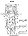
- the displacement control valve 50 regulates the amount of gas discharged from the crank chamber 5. As shown in Fig. 2, the displacement control valve 50 is provided with a lower first valve housing 60 and an upper second valve housing 70 that are coupled together.
- the first valve housing 60 is cylindrical with three spaces 61, 62, 63 formed inside. The diameter of these spaces increase in steps from the lower to the upper space.
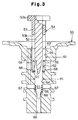
- Fig. 3 shows the first valve housing 60 before assembling the control valve 50. Prom among the three spaces 61, 62, 63, the first space 61, which is lowest, and the second, or middle, space 62 are connected through a lower through-hole 64, and the second space 62 and the third, or highest, space 63 are connected through an upper through-hole 65.
- the first space 61, lower through-hole 64, second space 62, upper through-hole 65, and third space 63 are all circular and coaxial.
- the first space 61 and the lower through-hole 64 have the same diameter d1.
- the second space 62 and the upper through-hole 65 have the same diameter d2.
- the inner diameter d2 is larger than the inner diameter d1.
- a first port 66 is formed directly below the first space 61.
- the first port 66 extends axially through the first valve housing 60.
- a plurality of second ports 67 are formed to extend substantially perpendicular to the first space 61. These second ports 67 extend radially through the first valve housing 60.
- a plurality of third ports 68 are formed to extend substantially perpendicular to the second space 62. These second ports 67 extend radially through the first valve housing 60.
- the first port 66 connects to the crank chamber 5 through the upstream section 27A of the bleed passage
- the second port 67 connects to the suction chamber 21 through the downstream section 27B of the bleed passage
- the third port 68 connects to the discharge chamber 22 through the connecting passage 28.
- An annular stepped portion, or valve seat 69 is defined between the first port 66 and the first space 61. The stepped portion functions as a valve seat and a spring seat.
- a pin-like actuator 54 is inserted through the first valve housing 60 from the third space 63 to the first port 66.
- the actuator 54 includes a valve body 51, a rod 52 and a pressure receiving body 53.
- the valve body 51 is integrally formed with the rod 52 and functions as a tapered needle valve extending from the end of the rod 52.
- the rod 52 is produced from a metallic material that resists wear and has excellent durability.
- the pressure receiving body 53 is cylindrical and fitted to the proximal end of the rod 52.
- the pressure receiving body 53 can be securely fixed to the rod 52 or can be movably engaged with the rod 52.
- the pressure receiving body 53 is produced from a metallic or resin material (for example, engineering plastic) that costs less than the metallic material used for the rod 52.
- the pressure receiving body 53 has a flange 53a.
- the valve body 51, rod 52, and the pressure receiving body 53 are all coaxial and have a circular cross-section.
- the outer diameter of the rod 52 is substantially equal to the inner diameter dl of the lower through-hole 64.
- the outer diameter of the principal portion of the pressure receiving body 53 is substantially equal to the inner diameter d2 of the upper through-hole 65.
- the actuator 54 is supported by a secondary retention spring 55, which is located in the first space 61, and a main retention spring 56, which is located in the second space 62.
- the springs 55, 56 allow the actuator to move in the axial direction within the first valve housing 60.
- the retention springs 55, 56 urge the actuator 54 upward and prevent the valve body 51 from strongly biting into the valve seat 69.
- the rod 52 is inserted into the lower through-hole 64 thereby sealing the upper through-hole 65.
- the first space 61 defines a valve chamber that contains the valve body 51 and is disconnected from the second space 62.
- the bleed passage is formed between the crank chamber 5 and the suction chamber 21.
- the bleed passage includes the upstream section 27A, the first port 66, the valve chamber 61, the second port 67, and the downstream section 27B.
- the valve body 51 regulates the size of the gap between the valve seat in accordance with the position inside the valve chamber 61 or, in other words, the amount the bleed passage opens.
- the suction pressure Ps reaches the valve chamber 61 through the downstream bleed passage 27B and the second port 67.
- the pressure receiving body 53 is inserted into the upper through-hole 65, which seals the through-hole 65.
- the second space 62 defines a pressure compensation chamber 62 that is disconnected from the third space 63.
- the discharge pressure Pd reaches the pressure compensation chamber 62 through the connecting passage 28 and third port 68.
- the lower end surface 53b of the pressure receiving body 53 is exposed to the inside of the pressure compensation chamber 62 and functions as a pressure receiving surface to receive the discharge pressure Pd.
- the pressure receiving body 53 is urged upward with a force corresponding to the discharge pressure Pd. This force acts on the lower end surface 53b (pressure receiving surface).
- the second valve housing 70 is coupled to the upper end of the first valve housing 60 with a diaphragm 57, which acts as a pressure sensitive member, arranged in between.
- the space at the lower side of the diaphragm 57 is the third space 63.
- This third space 63 is defined as a pressure sensitive chamber 63 by the diaphragm 57.
- the upper end of the rod 52 is arranged inside the pressure sensitive chamber 63, and the flange 53a of the pressure receiving body 53 is secured to the lower surface of the diaphragm 57.
- the flange 53a has a relatively large diameter, which increases the contact area against the diaphragm 57. This makes it easy to connect the flange to the diaphragm 57.
- a connecting passage 58 is formed inside the first valve housing 60.
- the passage 58 allows the pressure sensitive chamber 63 to pass through the valve chamber 61 and the second port 67.
- the connecting passage 58, the second port 67, and the downstream section 27B of the bleed passage form a manometry passage to direct suction pressure Ps to the pressure sensitive chamber 63.
- an adjuster 71 is engaged into the upper portion of the second valve housing 70.
- An opening 71a is formed at the center of the adjuster 71.
- the opening 71a allows the space (space above the diaphragm 57) inside the second valve housing 70 to be opened to the atmosphere. Atmospheric pressure is used as a criterion pressure.
- a set spring 72 is located inside the second valve housing 70.
- the upper end of the set spring 72 contacts the adjuster 71 and the lower end contacts a spring seat 73.
- the compressive force of the set spring 72 is applied to the diaphragm 57 through the spring seat 73, a ball 74 and a ball seat 75.
- the ball seat 75 is mounted to the upper surface of the diaphragm 57.
- This target suction pressure Pset can be changed by adjusting the position of the adjuster 71 in the axial direction with respect to the second valve housing 70.
- the pressure sensitive mechanism includes the diaphragm 57, the adjuster 71, the set spring 72, the spring seat 73, the ball 74, and the ball seat 75.
- the pressure sensitive mechanism determines the target suction pressure Pset and moves the actuator 54 in accordance with changes in the suction pressure Ps.
- the pressure sensitive mechanism includes the diaphragm 57 and activates the valve body 51 such that the suction pressure Ps is maintained at approximately the target suction pressure Pset.
- the function of a compressor that incorporates an air conditioning circuit of an HVAC system is to maintain the pressure Ps' at the outlet of the evaporator 33 close to a desired value that reflects the air conditioning load. Consequently, the compressor uses the control valve 50 to perform feedback control of the inclination angle of the swash plate 12 (discharge amount) such that the pressure (suction pressure Ps) at the suction chamber 21, which is almost equal to the pressure Ps' at the outlet of the evaporator 33, is maintained at the target suction pressure Pset.
- discharge pressure Pd discharge pressure
- the pressure receiving body 53 is provided to correct the difference between both pressures Ps, Ps'. In other words, as the discharge pressure Pd increases, the upward force of the pressure receiving body 53 increases. This upward force of the pressure receiving body 53 reduces and cancels the force of the set spring 72, which presses the diaphragm 57 downward. Stated differently, the pressure receiving body 53 compensates the target suction pressure Pset in accordance with the discharge pressure Pd. Therefore, even if the discharge pressure Pd is high, the opening of the control valve 50 is controlled to stabilize the pressure Ps' at the outlet of the evaporator 33 close to a desired value.
- the diameter (or cross-sectional area) of the actuator 54 that consists of the valve body 51, the rod 52 and the pressure receiving body 53 becomes smaller at locations further from the diaphragm 37.
- the openings (including the spaces 61, 62, 63 and the through-holes 64, 65) formed in the first valve housing 60 have a diameter (or cross-sectional area) that changes to adjust to the shape of the actuator 54. This makes it easy to manufacture the actuator 54 and the first valve housing 60 and makes it possible to reduce the number of parts compared to a conventional compressor. This reduction in the number of parts improves the durability of the control valve 50.
- the actuator 54 into the first valve housing 60 just by inserting a pre-assembled actuator 54 from the opening at the upper side of the first valve housing 60 (refer to Fig. 3). Accordingly, the assembly of the control valve is simpler compared to a conventional valve, which reduces the number of assembly steps and the costs.
- the actuator 54 is an integrated member including the valve body 51 and the rod 52 and is formed separately from the pressure receiving body 53. Because of this, it is possible to form the pressure receiving body 53 using a comparatively low-cost metallic or resin material that does not require much durability. This improves the design from the viewpoint of cost. Further, high-cost materials are used for the valve body 51 to avoid damage to the valve body 51 and the valve seat 69.
- the pressure receiving body 53 is fitted to the rod 52 so as to encompass the rod 52. This decreases the length of the actuator 54 in the axial direction, which limits the axial length of the control valve 50. Moreover, the size of the pressure receiving body 53 can be freely set without regard to the size of the rod 52.
- the contact area between the inner peripheral surface of the lower through-hole 64 and the outer peripheral surface of the rod 52 is relatively large. Consequently, the lower through-hole 64 is reliably sealed by the rod 52 even if a special seal member is not provided. Due to the same reasons, the area of contact between the inner peripheral surface of the upper through-hole 65 and the outer peripheral surface of the pressure receiving body 53 serves as a seal.
- the actuator is elastically supported using the two retention springs 56, 55. Consequently, the load per spring is reduced.
- the present invention can also be embodied as described below.
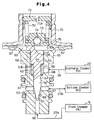
- valve body 51, the rod 52 and the pressure receiving body 53 are integral and made from the same material to form the actuator 54.
- the secondary retention spring 55 (refer to Fig. 2) may be omitted to simplify the internal construction of the valve chamber 61. The number of parts are reduced in this embodiment.
- the three members 51, 52, 53 have shapes, the diameters (or cross-sectional areas) of which change in a stepped manner from the lower end to the upper end, to facilitate machining.
- valve body 51 does not have a tapered shape and has a flat end.
- end of the valve body 51 is semi-spherical. As long as the diameter (or cross-sectional area) of the valve body 51 does not exceed the diameter (or cross-sectional area) of the rod 52, the valve body 51 can be formed in any shape.
- a tapered surface 81 is formed on the stepped portion between the valve body 51 and the rod 52 and a tapered surface 82 is formed on the stepped portion between the pressure compensation chamber 62 and the lower through-hole 64.
- a tapered surface 83 is formed on the lower end of the peripheral edge of the pressure receiving body 53, and a tapered surface 84 is formed on the stepped portion between the pressure sensitive chamber 63 and the upper through-hole 65.
- the tapered surfaces 81, 82, 83 and 84 make it easier to insert the actuator 54 into the lower through-hole 64.
- an upper end (proximal end) 52a of the rod 52 is formed with a diameter larger than that of the pressure receiving body 53, and the upper end surface of the pressure receiving body 53 defines a conical surface 85. This makes it easier to insert the rod 52 into the pressure receiving body 53, which simplifies the insertion of the rod 52 in the pressure receiving body 53. Moreover, the large diameter upper end member 52a makes it easier to mount the rod 52 to the diaphragm 57.
- a small space 86 is formed between the rod 52 and the pressure receiving body 53.
- the space 86 is sealed by a ring seal 87, which allows the rod 52 and the pressure receiving body 53 to move radially. This compensates for axes misalignment between the lower through-hole 64 and the upper through-hole 65 that may be caused by machining tolerances. Consequently, it becomes possible to lower the processing accuracy required for the first valve housing 60, which simplifies the manufacture of the first valve housing 60.
- the ring seal 87 acts to prevent gas leaks from the pressure compensation chamber 62 to the pressure sensitive chamber 63. Further, it is preferred that the ring seal 87 be formed by an elastic material such as rubber that allows movement in the radial direction between the rod 52 and the pressure receiving body 53.
- the seal material can be provided between the inner peripheral surface of the lower through-hole 64 and the outer peripheral surface of the rod 52.
- the seal material can also be provided between the inner peripheral surface of the upper through-hole 65 and the outer peripheral surface of the pressure receiving body 53.
- a bellows can be used as a pressure sensitive member in place of the diaphragm 57.
- the present invention can also be applied to a control valve that can change the target suction pressure Pset in response to external commands.
- an actuator for instance, an electromagnetic solenoid
- a pressure sensitive member diaphragm 57
- the suction pressure Ps is detected by a sensor, and a computer regulates the electromagnetic transfer force of the electromagnetic solenoid in response to the detected pressure.
- This electromagnetic transfer force is equivalent to the force of the set spring 72 of Fig. 2 and the target suction pressure Pset can be suitably changed in response the electromagnetic transfer force.
- the cross-sectional shape of the actuator 54 and the cross-sectional shape of the spaces 61, 62, 62 and the through-holes 64, 65 defined in the first valve housing 60 can also be other than circular.
- the present invention is not limited to the swash plate type compressor shown in Fig. 1 but can also be applied to other types of variable displacement compressors.
- a displacement control valve for controlling the amount of gas flowing through a bleed passage (27A, 27B) of a compressor to adjust pressure in a crank chamber (5) of the compressor.
- the control valve includes a housing (60), a pressure sensitive member, or diaphragm (57), which is arranged in the housing (60), and an actuator (54) extending from the diaphragm (57) and arranged in the housing (60).
- a valve body (51) is formed integrally with the distal end of the actuator (54).
- a pressure receiving body (53) is provided at the proximal end of the actuator (54).
- the diaphragm (57) drives the actuator (54) in accordance with a suction pressure.
- the pressure receiving body (53) urges the diaphragm (57) in a single direction in accordance with a discharge pressure.
- the diameter (or cross-sectional are) of the actuator (54) decreases in a stepped-like manner in the axial direction. This simplifies manufacture and of the actuator (54) and facilitates assembly.
Abstract
Description
- The present invention relates to control valves for variable displacement compressors, which vary the amount of discharge of compressors by controlling the amount of gas discharged from a crank chamber of a variable displacement compressor.
- Variable displacement compressors, which vary displacement by controlling the inclination angle of tiltable swash plates disposed in a crank chamber within a compressor, are well known as compressors used in automobile air conditioners. In these compressors, the inclination angle of the swash plate is regulated by controlling the pressure of the gas (crank pressure Pc) in the crank chamber using a special valve.
- One method to control the crank pressure is called outlet control. This type of control method regulates the crank pressure by controlling the amount of gas discharged from the crank chamber using an outlet control valve located within a bleed passage that links the crank chamber and the suction chamber. Additionally, the suction chamber of the compressor is connected to the outlet of an evaporator of an external refrigerant circuit.
- In an ordinary outlet control valve, a pressure sensitive member deforms in response to changes in the pressure (suction pressure Ps) at the suction chamber, which corresponds to the pressure at the outlet of the evaporator. This in turn actuates the valve body. A target value is set in advance for the suction pressure (target suction pressure) depending on the amount of force applied to the pressure sensitive member. The control valve automatically controls the opening of the valve body such that the suction pressure Ps converges on the target suction pressure.
- When the pressure of the refrigeration gas (discharge pressure Pd) that discharges into the external refrigerant circuit from the compressor is high, the pressure loss within the external refrigerant circuit will increase significantly. This increase causes a difference to occur between the pressure Ps' at the outlet of the evaporator and the suction pressure Ps. Stated with more detail, the suction pressure Ps becomes higher than the pressure Ps' at the outlet of the evaporator as the discharge pressure Pd increases. The control valve uses the suction pressure Ps as the pressure Ps' at the outlet of the evaporator. Consequently, it becomes impossible for the difference between both pressures Ps and Ps' to accurately control pressure Ps' at the outlet of the evaporator.
- Technology that achieves this type of control sufficiently taking into consideration compensation for the difference between both pressures Ps and Ps' as well as the pressure Ps' at the outlet of the evaporator, has been proposed. For example, a control valve disclosed in Japanese Unexamined Patent Publication No. 3-53474 transfers changes in the discharge pressure Pd to the pressure sensitive member. The target suction pressure falls following increases in the discharge pressure Pd. As a result, the difference between the pressures Ps and Ps' is compensated for and the pressure Ps' at the outlet of the evaporator is accurately controlled.
- In contrast, a control valve disclosed in Japanese Unexamined Patent Publication No. 5-52182 includes a diaphragm (pressure sensitive member) that deforms in response to suction pressure changes, a spherical valve body actuated by means of the diaphragm, and a rod that transmits the displacement of the diaphragm to the valve body. A pressure correction mechanism is located between the diaphragm and the valve body to compensate for differences between the suction pressure and the pressure at the outlet of the evaporator. This pressure correction mechanism has a chamber where discharge pressure is introduced and the rod passes through the chamber.
- Because the valve body in the control valve of Japanese Unexamined Patent Publication No. 5-52182 is spherical, the valve body and the rod must be produced separately making the production of the control valve complicated. Further, the action of placing the valve body at established locations within the control valve and the action of placing the rod such that it passes through the chamber of the pressure correction mechanism must be carried out separately, making the assembly of the control valve tedious.
- It is an object of the present invention to provide control valves for variable displacement compressors with a construction simpler than conventional valves as well as with simpler assembly.
- To achieve the above object, the present invention provides a control valve for a variable displacement compressor. The control, valve adjusts the pressure of a crank chamber in the compressor to vary the compressor displacement. The compressor includes a suction pressure region to which suction pressure is communicated, a discharge pressure region to which a discharge pressure is communicated, and a bleed passage connecting the crank chamber to the suction pressure region. The control valve includes a housing, a pressure sensitive member arranged in the housing to deform in accordance with the suction pressure, and an actuator extending from the pressure sensitive member and arranged in the housing. The actuator includes a valve body for adjusting the opened amount of the bleed passage and a pressure receiving body for receiving the discharge pressure. The pressure sensitive member drives the valve body in accordance with the suction pressure. The pressure receiving body urges the pressure sensitive member in a single direction with a force corresponding to the discharge pressure, and the actuator is formed so that its cross-sectional area decreases in a stepped manner axially.
- Other aspects and advantages of the present invention will become apparent from the following description, taken in conjunction with the accompanying drawings, illustrating by way of example the principles of the invention.
- The invention, together with objects and advantages thereof, may best be understood by reference to the following description of the presently preferred embodiments together with the accompanying drawings in which:
- Fig. 1 is a cross-sectional view showing a variable displacement compressor according to a first embodiment of the present invention;
- Fig. 2 is a cross-sectional view of a displacement control valve of the compressor of Fig. 1;
- Fig. 3 is an schematic cross-sectional view showing one portion of the assembly procedure of the displacement control valve of Fig. 2;
- Fig. 4 is a cross-sectional view showing a displacement control valve according to a further embodiment of the present invention;
- Fig. 5 is a partial cross-sectional view showing a displacement control valve according to a further embodiment of the present invention;
- Fig. 6 is a partial cross-sectional view showing a displacement control valve according to a further embodiment of the present invention;
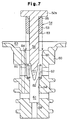
- Fig. 7 is a cross-sectional view showing a displacement control valve according to a further embodiment of the present invention;
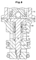
- Fig. 8 is a partial cross-sectional view showing a displacement control valve according to a further embodiment of the present invention.
-
- In the following, a displacement control valve according to the present invention and incorporated in a variable displacement type swash plate compressor will be described referring to Fig. 1 through Fig. 3.
- As shown in Fig. 1, the variable displacement type swash plate compressor includes a
cylinder block 1, a front housing member 2 joined to the front end of thecylinder block 1, and a rear housing member 4 joined to the rear end of thecylinder block 1 through avalve plate 3. Thecylinder block 1, front housing member 2,valve plate 3 and rear housing member 4 are held together with a plurality of bolts (not shown) to form the compressor housing. - A
crank chamber 5 is defined between thecylinder block 1 and the front housing member 2. Adrive shaft 6 is supported by thecylinder block 1 and the front housing member 2 with a plurality of radial bearings. - A bore housing a helical spring 7 and a thrust bearing 8 is formed substantially at the center of the
cylinder block 1. In thecrank chamber 5, arotating support 11 is fixed on thedrive shaft 6 to rotate integrally with thedrive shaft 6. Another thrust bearing 9 is located between therotating support 11 and an inner wall of the front housing member 2. Thedrive shaft 6 is supported in the axial direction by both thrust bearing 8, 9 and is urged toward the front by the spring 7. - The
drive shaft 6 is connected through anelectromagnetic clutch 40 to an engine E, which serves as an external power source. Theelectromagnetic clutch 40 includes apulley 42, anannular solenoid coil 43, and anarmature 45. Thepulley 42 is supported by abearing 41 at the front end of the front housing member 2 allowing it to rotate. Thearmature 45 is connected to thedrive shaft 6 by aleaf spring 44. - When electric current is supplied to the
coil 43, electromagnetic attraction is produced between thearmature 45 and thepulley 42, which causes thearmature 45 to engage thepulley 42, as shown in Fig. 1. Consequently, the driving power of the engine E is transmitted to thedrive shaft 6 through atransmission belt 46, thepulley 42, thearmature 45, and theleaf spring 44. When the supply of electric current to thecoil 43 is interrupted, thearmature 45 is separated from thepulley 42 by the force of theleaf spring 44 to interrupt the power transmission. Thus, the driving power of the engine E is selectively transmitted to thedrive shaft 6 by controlling the supply of electric current to thecoil 43. - A
swash plate 12, or drive plate, is housed in thecrank chamber 5. Thedrive shaft 6 passes through a hole formed at the center of theswash plate 12. Theswash plate 12 is connected through ahinge mechanism 13 to therotating support 11 and thedrive shaft 6. Thehinge mechanism 13 consists of a supportingarm 14 with a guide hole provided on therotating support 11, and aguide pin 15 with a spherical head on the front surface of theswash plate 12. Thehinge mechanism 13 causes theswash plate 12 and thedrive shaft 6 to rotate together. This permits theswash plate 12 to move in the axial direction of thedrive shaft 6 and to incline with respect to the axis of thedrive shaft 6. - A
coil spring 16 is fitted to thedrive shaft 6 between therotating support 11 and theswash plate 12. Thespring 16 urges theswash plate 12 in a direction decreasing the angle of inclination of theswash plate 12. Asnap ring 17 is fixed on thedrive shaft 6 between theswash plate 12 and thecylinder block 1. Thesnap ring 17 restricts the rearward movement of theswash plate 12 to determine the minimum inclination angle of theswash plate 12. The minimum inclination angle is, for example, 3 to 5 degrees. In contrast, the maximum inclination angle of theswash plate 12 is determined by the abutment of acounterweight 12a formed on theswash plate 12 against a restrictingsection 11a of therotating support 11. - A plurality of cylinder bores 1a (only one bore is shown) extend through the
cylinder block 1. The cylinder bores 1a are arranged at predetermined intervals along a circle drawn about the axis of thedrive shaft 6. A single-headedpiston 18 is located in eachcylinder bore 1a. Eachpiston 18 is connected to theswash plate 12 through a pair ofshoes 19. - A
suction chamber 21, the pressure of which is referred to as the suction pressure Ps, and adischarge chamber 22, the pressure of which is referred to as the discharge pressure Pd, are defined in the rear housing member 4. Thevalve plate 3 contains asuction port 23, asuction valve 24, adischarge port 25 and adischarge valve 26 for eachcylinder bore 1a. Thesuction chamber 21 is connected to each cylinder bore 1a through the correspondingsuction port 23. Eachcylinder bore 1a is connected to thedischarge chamber 22 through thecorresponding discharge port 25. - In the compressor shown in Fig. 1, the
drive shaft 6 is rotated when the engine E is driven, and theswash plate 12 rotates with the rotation of theshaft 6. The rotational movement of theswash plate 12 is converted through theshoes 19 into reciprocating movement of thepistons 18. This reciprocating movement compresses a refrigerant gas drawn from thesuction chamber 21, through thevalve plate 3, into eachcylinder bore 1a. Compressed refrigerant gas is discharged from each cylinder bore 1a into thedischarge chamber 22. - The inclination angle of the
swash plate 12 is determined according to various moments applied to theswash plate 12. The moments include a rotational moment, which is based on the centrifugal force of therotating swash plate 12, a spring force moment, which is based on the force of thespring 16, and a gas pressure moment. The rotational moment continually acts on theswash plate 12 to increase the inclination angle. The gas pressure moment depends on the mutual relationship of the reactive force of compression acting upon thepistons 18 during the compression strokes, the internal pressure in thecylinder bore 1a acting upon thepistons 18 during the suction strokes, and the pressure in the crank chamber 5 (crank pressure Pc). The gas pressure moment acts on theswash plate 12 to decrease the inclination angle. - In this embodiment, when the crank pressure Pc is maintained at a high pressure, the sum of the gas pressure moment and the
spring 16 force moment becomes greater than the rotational moment. Accordingly, theswash plate 12 shifts to the minimum inclination angle position. The sum of the moment based on the gas pressure and the moment based on the spring force is balanced with the moment of the rotational movement by adjusting the crank pressure Pc. As a result, the inclination of theswash plate 12 is set at a desired angle between the minimum inclination angle and the maximum inclination angle. The stroke of eachpiston 18, or the discharge displacement of the compressor, is adjusted according to the inclination angle of theswash plate 12. - As shown in Figs. 1 and 2, the mechanism for controlling the crank pressure Pc consists of a
displacement control valve 50 and a plurality ofpassages bleed passage crank chamber 5 to thesuction chamber 21. Thedisplacement control valve 50 is located in thebleed passage displacement control valve 50 regulates the amount of gas discharged from thecrank chamber 5 to thesuction chamber 21 by controlling the opening amount of thebleed passage control valve 50 will be described in detail later. Thedownstream section 27B of the bleed passage, which is downstream of thecontrol valve 50, also functions as a manometry passage to direct suction pressure Ps to thecontrol valve 50. - Further, the compressor housing is provided with a connecting
passage 28 connecting thecontrol valve 50 to thedischarge chamber 22 as well as anauxiliary supply passage 29 connecting thecrank chamber 5 to thedischarge chamber 22. Theauxiliary supply passage 29 is provided with a fixedrestriction 29a. The gas supply to the crankchamber 5 depends mainly on leakage from the gap between thepiston 18 and the cylinder bore 1a during compression strokes. This is called blow-by gas. The supply of blow-by gas, however, is unstable. Theauxiliary supply passage 29, which has the fixedrestriction 29a, compensates for this instability. - The
discharge chamber 22 and thesuction chamber 21 are connected to each other through an externalrefrigerant circuit 30. The externalrefrigerant circuit 30 forms, together with the compressor, a cooling circuit of an automobile air conditioner. The externalrefrigerant circuit 30 is provided with acondenser 31, athermostatic expansion valve 32, and anevaporator 33. The valve position of theexpansion valve 32 is controlled based on the temperature detected by atemperature detector 34 located at the outlet of theevaporator 33 and the pressure at the outlet of theevaporator 33. Theexpansion valve 32 provides liquefied refrigerant to theevaporator 33 depending on the thermal load applied to the refrigerator circuit. This adjusts the flow rate of the refrigerant in the externalrefrigerant circuit 30. - The
displacement control valve 50 regulates the amount of gas discharged from thecrank chamber 5. As shown in Fig. 2, thedisplacement control valve 50 is provided with a lowerfirst valve housing 60 and an uppersecond valve housing 70 that are coupled together. - As shown in Figs. 2 and 3, the
first valve housing 60 is cylindrical with threespaces first valve housing 60 before assembling thecontrol valve 50. Prom among the threespaces first space 61, which is lowest, and the second, or middle,space 62 are connected through a lower through-hole 64, and thesecond space 62 and the third, or highest,space 63 are connected through an upper through-hole 65. Thefirst space 61, lower through-hole 64,second space 62, upper through-hole 65, andthird space 63 are all circular and coaxial. Thefirst space 61 and the lower through-hole 64 have the same diameter d1. Thesecond space 62 and the upper through-hole 65 have the same diameter d2. The inner diameter d2 is larger than the inner diameter d1. - A
first port 66 is formed directly below thefirst space 61. Thefirst port 66 extends axially through thefirst valve housing 60. A plurality ofsecond ports 67 are formed to extend substantially perpendicular to thefirst space 61. Thesesecond ports 67 extend radially through thefirst valve housing 60. Lastly, a plurality ofthird ports 68 are formed to extend substantially perpendicular to thesecond space 62. Thesesecond ports 67 extend radially through thefirst valve housing 60. - As shown in Fig. 2, when the
control valve 50 is installed in the compressor, thefirst port 66 connects to the crankchamber 5 through theupstream section 27A of the bleed passage, thesecond port 67 connects to thesuction chamber 21 through thedownstream section 27B of the bleed passage, and thethird port 68 connects to thedischarge chamber 22 through the connectingpassage 28. An annular stepped portion, orvalve seat 69, is defined between thefirst port 66 and thefirst space 61. The stepped portion functions as a valve seat and a spring seat. - As shown Figs. 2 and 3, a pin-
like actuator 54 is inserted through thefirst valve housing 60 from thethird space 63 to thefirst port 66. Theactuator 54 includes avalve body 51, arod 52 and apressure receiving body 53. Thevalve body 51 is integrally formed with therod 52 and functions as a tapered needle valve extending from the end of therod 52. Therod 52 is produced from a metallic material that resists wear and has excellent durability. Thepressure receiving body 53 is cylindrical and fitted to the proximal end of therod 52. Thepressure receiving body 53 can be securely fixed to therod 52 or can be movably engaged with therod 52. Further, thepressure receiving body 53 is produced from a metallic or resin material (for example, engineering plastic) that costs less than the metallic material used for therod 52. Thepressure receiving body 53 has aflange 53a. - The
valve body 51,rod 52, and thepressure receiving body 53 are all coaxial and have a circular cross-section. The outer diameter of therod 52 is substantially equal to the inner diameter dl of the lower through-hole 64. The outer diameter of the principal portion of thepressure receiving body 53 is substantially equal to the inner diameter d2 of the upper through-hole 65. - As shown in Fig. 2, the
actuator 54 is supported by asecondary retention spring 55, which is located in thefirst space 61, and amain retention spring 56, which is located in thesecond space 62. Thesprings first valve housing 60. The retention springs 55, 56 urge theactuator 54 upward and prevent thevalve body 51 from strongly biting into thevalve seat 69. - In addition, with the control valve in an assembled state as shown in Fig. 2, the
rod 52 is inserted into the lower through-hole 64 thereby sealing the upper through-hole 65. In this state, thefirst space 61 defines a valve chamber that contains thevalve body 51 and is disconnected from thesecond space 62. As a result, the bleed passage is formed between thecrank chamber 5 and thesuction chamber 21. The bleed passage includes theupstream section 27A, thefirst port 66, thevalve chamber 61, thesecond port 67, and thedownstream section 27B. Thevalve body 51 regulates the size of the gap between the valve seat in accordance with the position inside thevalve chamber 61 or, in other words, the amount the bleed passage opens. The suction pressure Ps reaches thevalve chamber 61 through thedownstream bleed passage 27B and thesecond port 67. - The
pressure receiving body 53 is inserted into the upper through-hole 65, which seals the through-hole 65. As a result, thesecond space 62 defines apressure compensation chamber 62 that is disconnected from thethird space 63. The discharge pressure Pd reaches thepressure compensation chamber 62 through the connectingpassage 28 andthird port 68. Thelower end surface 53b of thepressure receiving body 53 is exposed to the inside of thepressure compensation chamber 62 and functions as a pressure receiving surface to receive the discharge pressure Pd. Thepressure receiving body 53 is urged upward with a force corresponding to the discharge pressure Pd. This force acts on thelower end surface 53b (pressure receiving surface). - The
second valve housing 70 is coupled to the upper end of thefirst valve housing 60 with adiaphragm 57, which acts as a pressure sensitive member, arranged in between. The space at the lower side of thediaphragm 57 is thethird space 63. Thisthird space 63 is defined as a pressuresensitive chamber 63 by thediaphragm 57. The upper end of therod 52 is arranged inside the pressuresensitive chamber 63, and theflange 53a of thepressure receiving body 53 is secured to the lower surface of thediaphragm 57. Theflange 53a has a relatively large diameter, which increases the contact area against thediaphragm 57. This makes it easy to connect the flange to thediaphragm 57. - A connecting
passage 58 is formed inside thefirst valve housing 60. Thepassage 58 allows the pressuresensitive chamber 63 to pass through thevalve chamber 61 and thesecond port 67. The connectingpassage 58, thesecond port 67, and thedownstream section 27B of the bleed passage form a manometry passage to direct suction pressure Ps to the pressuresensitive chamber 63. - As shown in Fig. 2, an
adjuster 71 is engaged into the upper portion of thesecond valve housing 70. Anopening 71a is formed at the center of theadjuster 71. Theopening 71a allows the space (space above the diaphragm 57) inside thesecond valve housing 70 to be opened to the atmosphere. Atmospheric pressure is used as a criterion pressure. - A
set spring 72 is located inside thesecond valve housing 70. The upper end of theset spring 72 contacts theadjuster 71 and the lower end contacts aspring seat 73. Thus, the compressive force of theset spring 72 is applied to thediaphragm 57 through thespring seat 73, aball 74 and aball seat 75. Theball seat 75 is mounted to the upper surface of thediaphragm 57. - The sum of the force of the atmospheric pressure (criterion pressure) acting on the
diaphragm 57 and the compressive force of theset spring 72 determines the target value Pset (target suction pressure) for the suction pressure Ps. This target suction pressure Pset can be changed by adjusting the position of theadjuster 71 in the axial direction with respect to thesecond valve housing 70. - In this embodiment, the pressure sensitive mechanism includes the
diaphragm 57, theadjuster 71, theset spring 72, thespring seat 73, theball 74, and theball seat 75. The pressure sensitive mechanism determines the target suction pressure Pset and moves theactuator 54 in accordance with changes in the suction pressure Ps. - While the compressor is operating, blow-by gas flows into the crank chamber S from the
cylinder bore 1a, and the high pressure gas inside thedischarge chamber 22 is supplied to the crankchamber 5 via theauxiliary supply passage 29. In thedisplacement control valve 50, thediaphragm 57 moves theactuator 54 in the axial direction in accordance with the suction pressure Ps applied to the pressuresensitive chamber 63 from thesuction chamber 21. The opening size of thebleed passage valve body 51 located on the end of theactuator 54. The refrigerant gas discharged from thecrank chamber 5 into thesuction chamber 21 changes in accordance with the opening size of the bleed passage and the crank pressure Pc is adjusted accordingly. The inclination angle of theswash plate 12 is determined in accordance with the crank pressure Pc, which changes the amount of gas discharged by the compressor. - The pressure sensitive mechanism includes the
diaphragm 57 and activates thevalve body 51 such that the suction pressure Ps is maintained at approximately the target suction pressure Pset. The function of a compressor that incorporates an air conditioning circuit of an HVAC system is to maintain the pressure Ps' at the outlet of theevaporator 33 close to a desired value that reflects the air conditioning load. Consequently, the compressor uses thecontrol valve 50 to perform feedback control of the inclination angle of the swash plate 12 (discharge amount) such that the pressure (suction pressure Ps) at thesuction chamber 21, which is almost equal to the pressure Ps' at the outlet of theevaporator 33, is maintained at the target suction pressure Pset. - When the pressure of the refrigeration gas (discharge pressure Pd) that discharges into the external
refrigerant circuit 30 from the compressor is high, the pressure loss within the externalrefrigerant circuit 30 will increase. This causes a difference between the pressure Ps' at the outlet of theevaporator 33 and the suction pressure Ps. For example, as the discharge pressure Pd grows large, the suction pressure Ps becomes smaller than the pressure Ps' at the outlet of theevaporator 33. - The
pressure receiving body 53 is provided to correct the difference between both pressures Ps, Ps'. In other words, as the discharge pressure Pd increases, the upward force of thepressure receiving body 53 increases. This upward force of thepressure receiving body 53 reduces and cancels the force of theset spring 72, which presses thediaphragm 57 downward. Stated differently, thepressure receiving body 53 compensates the target suction pressure Pset in accordance with the discharge pressure Pd. Therefore, even if the discharge pressure Pd is high, the opening of thecontrol valve 50 is controlled to stabilize the pressure Ps' at the outlet of theevaporator 33 close to a desired value. - In the following, the advantages of this embodiment will be described.
- The diameter (or cross-sectional area) of the
actuator 54 that consists of thevalve body 51, therod 52 and thepressure receiving body 53 becomes smaller at locations further from the diaphragm 37. The openings (including thespaces holes 64, 65) formed in thefirst valve housing 60 have a diameter (or cross-sectional area) that changes to adjust to the shape of theactuator 54. This makes it easy to manufacture theactuator 54 and thefirst valve housing 60 and makes it possible to reduce the number of parts compared to a conventional compressor. This reduction in the number of parts improves the durability of thecontrol valve 50. - In addition, it is possible to incorporate the
actuator 54 into thefirst valve housing 60 just by inserting apre-assembled actuator 54 from the opening at the upper side of the first valve housing 60 (refer to Fig. 3). Accordingly, the assembly of the control valve is simpler compared to a conventional valve, which reduces the number of assembly steps and the costs. - The
actuator 54 is an integrated member including thevalve body 51 and therod 52 and is formed separately from thepressure receiving body 53. Because of this, it is possible to form thepressure receiving body 53 using a comparatively low-cost metallic or resin material that does not require much durability. This improves the design from the viewpoint of cost. Further, high-cost materials are used for thevalve body 51 to avoid damage to thevalve body 51 and thevalve seat 69. - The
pressure receiving body 53 is fitted to therod 52 so as to encompass therod 52. This decreases the length of theactuator 54 in the axial direction, which limits the axial length of thecontrol valve 50. Moreover, the size of thepressure receiving body 53 can be freely set without regard to the size of therod 52. - The contact area between the inner peripheral surface of the lower through-
hole 64 and the outer peripheral surface of therod 52 is relatively large. Consequently, the lower through-hole 64 is reliably sealed by therod 52 even if a special seal member is not provided. Due to the same reasons, the area of contact between the inner peripheral surface of the upper through-hole 65 and the outer peripheral surface of thepressure receiving body 53 serves as a seal. - The actuator is elastically supported using the two retention springs 56, 55. Consequently, the load per spring is reduced.
- The present invention can also be embodied as described below.
- In a further embodiment according to the present invention, as shown in Fig. 4, the
valve body 51, therod 52 and thepressure receiving body 53 are integral and made from the same material to form theactuator 54. In this case, the secondary retention spring 55 (refer to Fig. 2) may be omitted to simplify the internal construction of thevalve chamber 61. The number of parts are reduced in this embodiment. Further, the threemembers - In a further embodiment according to the present invention, as shown in Fig. 5, the
valve body 51 does not have a tapered shape and has a flat end. In a further embodiment according to the present invention, as shown in Fig. 6, the end of thevalve body 51 is semi-spherical. As long as the diameter (or cross-sectional area) of thevalve body 51 does not exceed the diameter (or cross-sectional area) of therod 52, thevalve body 51 can be formed in any shape. - In another embodiment according to the present invention shown in Fig. 7, the installation of the
actuator 54 in thefirst valve housing 60 is facilitated by tapering various surfaces in thefirst valve housing 60 and theactuator 54. In the example shown in Fig. 7, atapered surface 81 is formed on the stepped portion between thevalve body 51 and therod 52 and atapered surface 82 is formed on the stepped portion between thepressure compensation chamber 62 and the lower through-hole 64. Further, atapered surface 83 is formed on the lower end of the peripheral edge of thepressure receiving body 53, and atapered surface 84 is formed on the stepped portion between the pressuresensitive chamber 63 and the upper through-hole 65. The tapered surfaces 81, 82, 83 and 84 make it easier to insert theactuator 54 into the lower through-hole 64. - In the embodiment of Fig. 7, an upper end (proximal end) 52a of the
rod 52 is formed with a diameter larger than that of thepressure receiving body 53, and the upper end surface of thepressure receiving body 53 defines aconical surface 85. This makes it easier to insert therod 52 into thepressure receiving body 53, which simplifies the insertion of therod 52 in thepressure receiving body 53. Moreover, the large diameterupper end member 52a makes it easier to mount therod 52 to thediaphragm 57. - In a further embodiment according to the present invention shown in Fig. 8, a
small space 86 is formed between therod 52 and thepressure receiving body 53. Thespace 86 is sealed by aring seal 87, which allows therod 52 and thepressure receiving body 53 to move radially. This compensates for axes misalignment between the lower through-hole 64 and the upper through-hole 65 that may be caused by machining tolerances. Consequently, it becomes possible to lower the processing accuracy required for thefirst valve housing 60, which simplifies the manufacture of thefirst valve housing 60. Thering seal 87 acts to prevent gas leaks from thepressure compensation chamber 62 to the pressuresensitive chamber 63. Further, it is preferred that thering seal 87 be formed by an elastic material such as rubber that allows movement in the radial direction between therod 52 and thepressure receiving body 53. - The seal material can be provided between the inner peripheral surface of the lower through-
hole 64 and the outer peripheral surface of therod 52. The seal material can also be provided between the inner peripheral surface of the upper through-hole 65 and the outer peripheral surface of thepressure receiving body 53. - A bellows can be used as a pressure sensitive member in place of the
diaphragm 57. - The present invention can also be applied to a control valve that can change the target suction pressure Pset in response to external commands. For example, an actuator (for instance, an electromagnetic solenoid) that can apply force to a pressure sensitive member (diaphragm 57) can be provided in a control valve. The suction pressure Ps is detected by a sensor, and a computer regulates the electromagnetic transfer force of the electromagnetic solenoid in response to the detected pressure. This electromagnetic transfer force is equivalent to the force of the
set spring 72 of Fig. 2 and the target suction pressure Pset can be suitably changed in response the electromagnetic transfer force. - The cross-sectional shape of the
actuator 54 and the cross-sectional shape of thespaces holes first valve housing 60 can also be other than circular. - The present invention is not limited to the swash plate type compressor shown in Fig. 1 but can also be applied to other types of variable displacement compressors.
- It should be apparent to those skilled in the art that the present invention may be embodied in many other specific forms without departing from the spirit or scope of the invention. Therefore, the present examples and embodiments are to be considered as illustrative and not restrictive, and the invention is not to be limited to the details given herein, but may be modified within the scope and equivalence of the appended claims.
- A displacement control valve for controlling the amount of gas flowing through a bleed passage (27A, 27B) of a compressor to adjust pressure in a crank chamber (5) of the compressor. The control valve includes a housing (60), a pressure sensitive member, or diaphragm (57), which is arranged in the housing (60), and an actuator (54) extending from the diaphragm (57) and arranged in the housing (60). A valve body (51) is formed integrally with the distal end of the actuator (54). A pressure receiving body (53) is provided at the proximal end of the actuator (54). The diaphragm (57) drives the actuator (54) in accordance with a suction pressure. The pressure receiving body (53) urges the diaphragm (57) in a single direction in accordance with a discharge pressure. The diameter (or cross-sectional are) of the actuator (54) decreases in a stepped-like manner in the axial direction. This simplifies manufacture and of the actuator (54) and facilitates assembly.
Claims (14)
- A control valve for a variable displacement compressor, wherein the control valve adjusts the pressure of a crank chamber (5) in the compressor to vary the compressor displacement, wherein the compressor includes a suction pressure region (21) to which suction pressure is communicated, a discharge pressure region (22) to which a discharge pressure is communicated, and a bleed passage (27A, 27B) connecting the crank chamber (5) to the suction pressure region (21), the control valve comprising:a housing (60); anda pressure sensitive member (57) arranged in the housing (60) to deform in accordance with the suction pressure, the control valve being characterized by:an actuator (54) extending from the pressure sensitive member (57) and arranged in the housing (60), wherein the actuator (54) includes a valve body (51) for adjusting the opened amount of the bleed passage (27A, 27B) and a pressure receiving body (53) for receiving the discharge pressure, wherein the pressure sensitive member (57) drives the valve body (51) in accordance with the suction pressure, wherein the pressure receiving body (53) urges the pressure sensitive member (57) in a single direction with a force corresponding to the discharge pressure, and the actuator (54) is formed so that its cross-sectional area decreases in a stepped manner axially.
- The control valve according to claim 1 characterized in that the cross-sectional area of the actuator (54) decreases in a stepped manner such that the cross-sectional area of the actuator (54) is smaller at locations further from the pressure sensitive member (57).
- The control valve according to claims 1 or 2 characterized in that the diameter of the actuator (54) decreases in a stepped manner axially.
- The control valve according to claim 3 characterized in that the valve body (51) is formed at a portion of the actuator (54) where the diameter is smallest.
- The control valve according to any one of claims 1 to 4 characterized in that the valve body (51) is formed integrally with the actuator (54).
- The control valve according to any one of claims 1 to 5 characterized in that the valve body (51) is tapered.
- The control valve according to any one of claims 1 to 6 characterized in that the actuator (54) includes a rod (52) formed integrally with the valve body (51), the diameter of the valve body (51) being equal to or smaller than that of the rod (52).
- The control valve according to claim 7 characterized in that the diameter of the pressure receiving body (53) is greater than that of the rod (52).
- The control valve according to claim 8 characterized in that the pressure receiving body (53) is formed separately from the rod (52) and fitted to the rod (52) so as to surround the rod (52).
- The control valve according to claim 9 characterized in that the rod (52) and the pressure receiving body (53) form a space (86) therebetween to allow radial movement between the rod (52) and the pressure receiving body (53), and wherein an elastic seal (87) is arranged between the rod (52) and the pressure receiving body (53).
- The control valve according to claim 8, wherein the pressure receiving body (53) is formed integrally with the rod (52).
- The control valve according to any one of claims 7 to 11 characterized in that the rod (52) has a proximal end, which is connected to the pressure sensitive member (57), and an opposite, distal end, the pressure receiving body (53) being arranged at the proximal end, and the valve body (51) being arranged at the distal end.
- The control valve according to any one of claims 1 to 12 characterized in that the housing (60) includes a bore (61, 62, 63, 64, 65) corresponding to the outer shape of the actuator (54) to accommodate the actuator (54).
- The control valve according to any one of claims 7 to 12 characterized in that the housing (60) includes a valve chamber (61) forming part of the bleed passage (27A, 27B), a pressure chamber (62) to which the discharge pressure is communicated, and a pressure sensitive chamber (63) to which the suction pressure is communicated, the valve chamber (61), the pressure chamber (62) and the pressure sensitive chamber (63) being arranged axially in the housing (60), the housing (60) further including a first bore (64) connecting the valve chamber (61) to the pressure chamber (62) and a second bore (65) connecting the pressure chamber (62) to the pressure sensitive chamber (63), wherein the valve body (51) is accommodated in the valve chamber (61), the rod (52) is inserted into the first bore (64) to seal the valve chamber (61) from the pressure chamber (62), and the pressure receiving body (53) is inserted into the second bore (65) to seal the pressure chamber (62) from the pressure sensitive chamber (63), wherein the pressure receiving body (53) has a pressure receiving surface (53b) for receiving the discharge pressure of the pressure chamber (62), and wherein the suction pressure of the pressure sensitive chamber (63) acts on the pressure sensitive member (57).
Applications Claiming Priority (2)
| Application Number | Priority Date | Filing Date | Title |
|---|---|---|---|
| JP5249599 | 1999-03-01 | ||
| JP11052495A JP2000249051A (en) | 1999-03-01 | 1999-03-01 | Control valve for variable displacement swash plate type compressor |
Publications (2)
| Publication Number | Publication Date |
|---|---|
| EP1033490A2 true EP1033490A2 (en) | 2000-09-06 |
| EP1033490A3 EP1033490A3 (en) | 2001-01-10 |
Family
ID=12916308
Family Applications (1)
| Application Number | Title | Priority Date | Filing Date |
|---|---|---|---|
| EP00104151A Withdrawn EP1033490A3 (en) | 1999-03-01 | 2000-02-29 | Control valve for variable displacement compressor |
Country Status (2)
| Country | Link |
|---|---|
| EP (1) | EP1033490A3 (en) |
| JP (1) | JP2000249051A (en) |
Cited By (5)
| Publication number | Priority date | Publication date | Assignee | Title |
|---|---|---|---|---|
| FR2836521A1 (en) * | 2002-02-28 | 2003-08-29 | Taiheiyo Kogyo Kk | Variable displacement compressor control valve for air-conditioner of vehicle, has pressure sensitive portion fixed to valve portion and having diaphragm that moves in relation to pressure in suction passage |
| US6715995B2 (en) | 2002-01-31 | 2004-04-06 | Visteon Global Technologies, Inc. | Hybrid compressor control method |
| EP1479907A2 (en) * | 2003-05-14 | 2004-11-24 | Kabushiki Kaisha Toyota Jidoshokki | By-pass device in variable displacement compressor |
| EP1522728A2 (en) * | 2003-10-08 | 2005-04-13 | Pacific Industrial Co., Ltd. | Pressure control valve |
| US7806666B2 (en) | 2005-06-08 | 2010-10-05 | Eagle Industry Co. Ltd. | Displacement control valve of variable displacement compressor |
Families Citing this family (1)
| Publication number | Priority date | Publication date | Assignee | Title |
|---|---|---|---|---|
| US6746214B2 (en) * | 2001-03-01 | 2004-06-08 | Pacific Industrial Co., Ltd. | Control valve for compressors and manufacturing method thereof |
Citations (1)
| Publication number | Priority date | Publication date | Assignee | Title |
|---|---|---|---|---|
| JPH0552182A (en) | 1991-02-27 | 1993-03-02 | Taiheiyo Kogyo Kk | Capacity control device of compressor |
Family Cites Families (3)
| Publication number | Priority date | Publication date | Assignee | Title |
|---|---|---|---|---|
| JPS62206277A (en) * | 1986-03-06 | 1987-09-10 | Toyoda Autom Loom Works Ltd | Mechanism for returning swing slant angle of wobble plate in swing swash plate type compressor |
| JPH06200875A (en) * | 1993-01-08 | 1994-07-19 | Toyota Autom Loom Works Ltd | Rocking swash plate type variable displacement compressor |
| JP3254872B2 (en) * | 1993-12-27 | 2002-02-12 | 株式会社豊田自動織機 | Clutchless one-sided piston type variable displacement compressor |
-
1999
- 1999-03-01 JP JP11052495A patent/JP2000249051A/en active Pending
-
2000
- 2000-02-29 EP EP00104151A patent/EP1033490A3/en not_active Withdrawn
Patent Citations (1)
| Publication number | Priority date | Publication date | Assignee | Title |
|---|---|---|---|---|
| JPH0552182A (en) | 1991-02-27 | 1993-03-02 | Taiheiyo Kogyo Kk | Capacity control device of compressor |
Cited By (7)
| Publication number | Priority date | Publication date | Assignee | Title |
|---|---|---|---|---|
| US6715995B2 (en) | 2002-01-31 | 2004-04-06 | Visteon Global Technologies, Inc. | Hybrid compressor control method |
| FR2836521A1 (en) * | 2002-02-28 | 2003-08-29 | Taiheiyo Kogyo Kk | Variable displacement compressor control valve for air-conditioner of vehicle, has pressure sensitive portion fixed to valve portion and having diaphragm that moves in relation to pressure in suction passage |
| EP1479907A2 (en) * | 2003-05-14 | 2004-11-24 | Kabushiki Kaisha Toyota Jidoshokki | By-pass device in variable displacement compressor |
| EP1479907A3 (en) * | 2003-05-14 | 2005-09-14 | Kabushiki Kaisha Toyota Jidoshokki | By-pass device in variable displacement compressor |
| EP1522728A2 (en) * | 2003-10-08 | 2005-04-13 | Pacific Industrial Co., Ltd. | Pressure control valve |
| EP1522728A3 (en) * | 2003-10-08 | 2006-01-18 | Pacific Industrial Co., Ltd. | Pressure control valve |
| US7806666B2 (en) | 2005-06-08 | 2010-10-05 | Eagle Industry Co. Ltd. | Displacement control valve of variable displacement compressor |
Also Published As
| Publication number | Publication date |
|---|---|
| EP1033490A3 (en) | 2001-01-10 |
| JP2000249051A (en) | 2000-09-12 |
Similar Documents
| Publication | Publication Date | Title |
|---|---|---|
| US6361283B1 (en) | Displacement control valve | |
| US5332365A (en) | Slant plate type compressor with variable capacity control mechanism | |
| EP0848164B1 (en) | Control valve in variable displacement compressor | |
| USRE35672E (en) | Slant plate type compressor with variable capacity control mechanism | |
| US6062824A (en) | Control valve | |
| US5165863A (en) | Slant plate type compressor with variable capacity control mechanism | |
| EP2182213B1 (en) | Variable displacement type compressor with displacement control mechanism | |
| US5890876A (en) | Control valve in variable displacement compressor | |
| US6358017B1 (en) | Control valve for variable displacement compressor | |
| US6352416B1 (en) | Device and method for controlling displacement of variable displacement compressor | |
| US5975859A (en) | Control valve in variable displacement compressor and its assembling method | |
| US5286172A (en) | Slant plate type compressor with variable capacity control mechanism | |
| US5842835A (en) | Variable displacement compressor and its assembling method | |
| US6234763B1 (en) | Variable displacement compressor | |
| EP1024286A2 (en) | Control valve for variable displacement compressor | |
| US6510699B2 (en) | Displacement control apparatus for variable displacement compressor | |
| US20040057840A1 (en) | Capacity control valve for variable displacement compressor | |
| EP1033490A2 (en) | Control valve for variable displacement compressor | |
| US6783332B2 (en) | Control valve of variable displacement compressor with pressure sensing member | |
| US20170211561A1 (en) | Variable displacement swash plate type compressor | |
| EP0947695B1 (en) | Control valve for a variable displacement swash plate compressor | |
| US5299918A (en) | Bearing for compressor drive shaft | |
| KR100225196B1 (en) | Slant plate type compressor with variable capacity control mechanism | |
| JP3952425B2 (en) | Control valve for variable capacity compressor, variable capacity compressor, and method for assembling control valve for variable capacity compressor | |
| KR970003249B1 (en) | Slant plate type compressor with variable capacity control mechanism |
Legal Events
| Date | Code | Title | Description |
|---|---|---|---|
| PUAI | Public reference made under article 153(3) epc to a published international application that has entered the european phase |
Free format text: ORIGINAL CODE: 0009012 |
|
| 17P | Request for examination filed |
Effective date: 20000229 |
|
| AK | Designated contracting states |
Kind code of ref document: A2 Designated state(s): DE FR IT |
|
| AX | Request for extension of the european patent |
Free format text: AL;LT;LV;MK;RO;SI |
|
| PUAL | Search report despatched |
Free format text: ORIGINAL CODE: 0009013 |
|
| AK | Designated contracting states |
Kind code of ref document: A3 Designated state(s): AT BE CH CY DE DK ES FI FR GB GR IE IT LI LU MC NL PT SE |
|
| AX | Request for extension of the european patent |
Free format text: AL;LT;LV;MK;RO;SI |
|
| AKX | Designation fees paid |
Free format text: DE FR IT |
|
| STAA | Information on the status of an ep patent application or granted ep patent |
Free format text: STATUS: THE APPLICATION IS DEEMED TO BE WITHDRAWN |
|
| 18D | Application deemed to be withdrawn |
Effective date: 20020903 |