EP1024286A2 - Control valve for variable displacement compressor - Google Patents
Control valve for variable displacement compressor Download PDFInfo
- Publication number
- EP1024286A2 EP1024286A2 EP00101797A EP00101797A EP1024286A2 EP 1024286 A2 EP1024286 A2 EP 1024286A2 EP 00101797 A EP00101797 A EP 00101797A EP 00101797 A EP00101797 A EP 00101797A EP 1024286 A2 EP1024286 A2 EP 1024286A2
- Authority
- EP
- European Patent Office
- Prior art keywords
- valve
- pressure
- chamber
- compressor
- opening
- Prior art date
- Legal status (The legal status is an assumption and is not a legal conclusion. Google has not performed a legal analysis and makes no representation as to the accuracy of the status listed.)
- Withdrawn
Links
- 238000006073 displacement reaction Methods 0.000 title claims abstract description 35
- 230000007246 mechanism Effects 0.000 claims abstract description 89
- 230000000717 retained effect Effects 0.000 claims description 6
- 230000008878 coupling Effects 0.000 claims 2
- 238000010168 coupling process Methods 0.000 claims 2
- 238000005859 coupling reaction Methods 0.000 claims 2
- 238000011144 upstream manufacturing Methods 0.000 claims 1
- 230000001276 controlling effect Effects 0.000 description 8
- 239000002826 coolant Substances 0.000 description 8
- 230000008859 change Effects 0.000 description 7
- XEEYBQQBJWHFJM-UHFFFAOYSA-N Iron Chemical group [Fe] XEEYBQQBJWHFJM-UHFFFAOYSA-N 0.000 description 6
- 239000003507 refrigerant Substances 0.000 description 6
- 230000007423 decrease Effects 0.000 description 5
- 238000001816 cooling Methods 0.000 description 3
- 230000000694 effects Effects 0.000 description 3
- 238000000034 method Methods 0.000 description 3
- 230000005540 biological transmission Effects 0.000 description 2
- 238000010276 construction Methods 0.000 description 2
- 238000003754 machining Methods 0.000 description 2
- 238000004519 manufacturing process Methods 0.000 description 2
- 230000004913 activation Effects 0.000 description 1
- 230000006835 compression Effects 0.000 description 1
- 238000007906 compression Methods 0.000 description 1
- 230000005494 condensation Effects 0.000 description 1
- 238000009833 condensation Methods 0.000 description 1
- 238000001514 detection method Methods 0.000 description 1
- 238000010438 heat treatment Methods 0.000 description 1
- 230000009467 reduction Effects 0.000 description 1
- 230000001105 regulatory effect Effects 0.000 description 1
- 230000004044 response Effects 0.000 description 1
- 238000000926 separation method Methods 0.000 description 1
Images
Classifications
-
- F—MECHANICAL ENGINEERING; LIGHTING; HEATING; WEAPONS; BLASTING
- F04—POSITIVE - DISPLACEMENT MACHINES FOR LIQUIDS; PUMPS FOR LIQUIDS OR ELASTIC FLUIDS
- F04B—POSITIVE-DISPLACEMENT MACHINES FOR LIQUIDS; PUMPS
- F04B27/00—Multi-cylinder pumps specially adapted for elastic fluids and characterised by number or arrangement of cylinders
- F04B27/08—Multi-cylinder pumps specially adapted for elastic fluids and characterised by number or arrangement of cylinders having cylinders coaxial with, or parallel or inclined to, main shaft axis
- F04B27/14—Control
- F04B27/16—Control of pumps with stationary cylinders
- F04B27/18—Control of pumps with stationary cylinders by varying the relative positions of a swash plate and a cylinder block
- F04B27/1804—Controlled by crankcase pressure
- F04B2027/1809—Controlled pressure
- F04B2027/1813—Crankcase pressure
-
- F—MECHANICAL ENGINEERING; LIGHTING; HEATING; WEAPONS; BLASTING
- F04—POSITIVE - DISPLACEMENT MACHINES FOR LIQUIDS; PUMPS FOR LIQUIDS OR ELASTIC FLUIDS
- F04B—POSITIVE-DISPLACEMENT MACHINES FOR LIQUIDS; PUMPS
- F04B27/00—Multi-cylinder pumps specially adapted for elastic fluids and characterised by number or arrangement of cylinders
- F04B27/08—Multi-cylinder pumps specially adapted for elastic fluids and characterised by number or arrangement of cylinders having cylinders coaxial with, or parallel or inclined to, main shaft axis
- F04B27/14—Control
- F04B27/16—Control of pumps with stationary cylinders
- F04B27/18—Control of pumps with stationary cylinders by varying the relative positions of a swash plate and a cylinder block
- F04B27/1804—Controlled by crankcase pressure
- F04B2027/1822—Valve-controlled fluid connection
- F04B2027/1827—Valve-controlled fluid connection between crankcase and discharge chamber
-
- F—MECHANICAL ENGINEERING; LIGHTING; HEATING; WEAPONS; BLASTING
- F04—POSITIVE - DISPLACEMENT MACHINES FOR LIQUIDS; PUMPS FOR LIQUIDS OR ELASTIC FLUIDS
- F04B—POSITIVE-DISPLACEMENT MACHINES FOR LIQUIDS; PUMPS
- F04B27/00—Multi-cylinder pumps specially adapted for elastic fluids and characterised by number or arrangement of cylinders
- F04B27/08—Multi-cylinder pumps specially adapted for elastic fluids and characterised by number or arrangement of cylinders having cylinders coaxial with, or parallel or inclined to, main shaft axis
- F04B27/14—Control
- F04B27/16—Control of pumps with stationary cylinders
- F04B27/18—Control of pumps with stationary cylinders by varying the relative positions of a swash plate and a cylinder block
- F04B27/1804—Controlled by crankcase pressure
- F04B2027/1822—Valve-controlled fluid connection
- F04B2027/1831—Valve-controlled fluid connection between crankcase and suction chamber
-
- F—MECHANICAL ENGINEERING; LIGHTING; HEATING; WEAPONS; BLASTING
- F04—POSITIVE - DISPLACEMENT MACHINES FOR LIQUIDS; PUMPS FOR LIQUIDS OR ELASTIC FLUIDS
- F04B—POSITIVE-DISPLACEMENT MACHINES FOR LIQUIDS; PUMPS
- F04B27/00—Multi-cylinder pumps specially adapted for elastic fluids and characterised by number or arrangement of cylinders
- F04B27/08—Multi-cylinder pumps specially adapted for elastic fluids and characterised by number or arrangement of cylinders having cylinders coaxial with, or parallel or inclined to, main shaft axis
- F04B27/14—Control
- F04B27/16—Control of pumps with stationary cylinders
- F04B27/18—Control of pumps with stationary cylinders by varying the relative positions of a swash plate and a cylinder block
- F04B27/1804—Controlled by crankcase pressure
- F04B2027/184—Valve controlling parameter
- F04B2027/1854—External parameters
-
- F—MECHANICAL ENGINEERING; LIGHTING; HEATING; WEAPONS; BLASTING
- F04—POSITIVE - DISPLACEMENT MACHINES FOR LIQUIDS; PUMPS FOR LIQUIDS OR ELASTIC FLUIDS
- F04B—POSITIVE-DISPLACEMENT MACHINES FOR LIQUIDS; PUMPS
- F04B27/00—Multi-cylinder pumps specially adapted for elastic fluids and characterised by number or arrangement of cylinders
- F04B27/08—Multi-cylinder pumps specially adapted for elastic fluids and characterised by number or arrangement of cylinders having cylinders coaxial with, or parallel or inclined to, main shaft axis
- F04B27/14—Control
- F04B27/16—Control of pumps with stationary cylinders
- F04B27/18—Control of pumps with stationary cylinders by varying the relative positions of a swash plate and a cylinder block
- F04B27/1804—Controlled by crankcase pressure
- F04B2027/184—Valve controlling parameter
- F04B2027/1859—Suction pressure
Definitions
- the present invention relates to control valves for variable displacement compressors, which vary the inclination angle of a swash plate by changing the internal pressure of a crank chamber to change the displacement.
- outlet control is one method for controlling the internal pressure of the crank chamber.
- a high-pressure coolant gas having a pressure corresponding to the discharge pressure is constantly supplied at a predetermined flow rate to the crank chamber, while the flow rate of gas from the crank chamber is controlled by a control valve.
- the control valve controls the internal pressure of the crank chamber (crank pressure Pc).
- crank pressure Pc crank pressure
- the control valve disclosed in Japanese Unexamined Patent Publication No. 5-99136 is provided with a first valve element that selectively opens and closes a supply passage, which connects a discharge chamber and a crank chamber, and a second valve element that selectively opens and closes a bleed passage, which connects the crank chamber and a suction chamber.
- a rod connected to the two valve elements is electromagnetically driven by a solenoid.
- the first valve element and the second valve element are completely separated, and the first and second valve elements do not open simultaneously.
- the rod is connected to the second valve element to be movable relative to the second valve element. Accordingly, even after the second valve element is seated, the seal between the second valve element and the rod tends to be inadequate, making it difficult to avoid gas leakage from the crank chamber to the suction chamber.
- the control valve disclosed in Japanese Unexamined Patent Publication No. 10-103249 is provided with a first valve element that selectively opens and closes a supply passage, which connects a discharge chamber to a crank chamber, and a second valve element that adjusts the size of an opening of a bleed passage, which connects the crank chamber to a suction chamber.
- a first rod and a second rod extend from the first valve element and the second valve element respectively.
- the second rod is fitted to the first rod to be movable relative to the first rod, so that the first and second valve elements can be operated independently.
- the rods are connected to respective plungers, and the plungers are electromagnetically driven by a common coil.
- Japanese Unexamined Patent Publication No. 10-103249 merely proposes a control valve for a specific clutchless, swash plate-type, variable displacement compressor. That is, the compressor of this publication has a shutter near one end of the drive shaft for shutting off the suction chamber from a suction passage, which communicates with an external refrigerant circuit. The shutter stops the flow of coolant gas in the external refrigerant circuit. When the shutter blocks the suction passage from the suction chamber, two regions with different suction pressures (i.e., the suction passage and the suction chamber) are defined.
- the control valve to be used with the compressor of publication No. 10-103249 has a pressure detecting chamber, to which the pressure in the suction passage is introduced, and a second valve chamber, to which the pressure in the suction chamber is introduced.
- a bellows is located in the pressure detecting chamber, while the second valve element is located in the second valve chamber.
- the pressure detecting chamber and the second valve chamber are isolated from each other by a diaphragm. Accordingly, the suction passage and the suction chamber are not connected to each other through the internal space of the control valve.
- the bellows and the second valve element are connected by a pressure detecting rod. The bellows moves the second valve element depending on the suction pressure introduced from the suction passage to the pressure detecting chamber.
- the pressure detecting rod must be located to pass through the diaphragm between the pressure detecting chamber and the second valve chamber.
- high accuracy machining is required so that no clearance exists between the pressure detecting rod and the diaphragm. This makes the manufacture of such a control valve difficult and increases the cost significantly.
- the present invention provides a control valve for a variable displacement compressor.
- the control valve adjusts the pressure in a crank chamber of the compressor to vary the compressor displacement.
- the compressor includes a suction pressure zone, the pressure of which is a suction pressure, a discharge pressure zone, the pressure of which is a discharge pressure, a bleed passage for connecting the crank chamber to the suction pressure zone, and a supply passage for connecting the crank chamber to the discharge pressure zone.
- the control valve comprises a housing, a first valve mechanism retained in the housing to selectively open and close the supply passage, a second valve mechanism retained in the housing to adjust the flow rate of gas released from the crank chamber to the suction pressure zone through the bleed passage, and a solenoid mechanism retained in the housing to independently actuate the first valve mechanism and the second valve mechanism.
- the first valve mechanism includes a first valve opening defined in the housing. The first valve opening forms part of the supply passage.
- a first valve element selectively opens and closes the first valve opening.
- a first plunger is connected to the first valve element.
- the second valve mechanism includes a second valve opening defined in the housing. The second valve opening forms part of the bleed passage. A second valve element adjusts the opening size of the second valve opening.
- a pressure sensing member moves the second valve element in accordance with the suction pressure.
- a second plunger is connected to the second valve element.
- the solenoid mechanism includes a coil. Current supplied to the coil produces an electromagnetic force for independently biasing the first and second plungers in accordance with the level of the current.
- a pressure chamber is defined in the housing to accommodate the second valve element and the pressure sensing member. The pressure chamber is exposed to the suction pressure.
- a swash plate compressor is provided with a cylinder block 1, a front housing member 2 joined with the front end of the cylinder block 1, and a rear housing member 4 joined with the rear end of the cylinder block 1 through a valve plate 3.
- the cylinder block 1, the front housing 2, the valve plate 3 and the rear housing member 4 are held together with a plurality of through bolts (not shown) to form a compressor housing.
- a crank chamber 5 is defined between the cylinder block 1 and the front housing member 2.
- a drive shaft 6 is supported by the cylinder block 1 and the front housing member 2 with a plurality of radial bearings.
- a bore housing a helical spring 7 and a thrust bearing 8 is formed substantially at the center of the cylinder block 1.
- a rotating support 11 is fixed on the drive shaft 6 to rotate integrally with the drive shaft 6.
- Another thrust bearing 9 is located between the rotating support 11 and an inner wall of the front housing member 2. The drive shaft 6 is urged toward the front housing member 2 by the spring 7.
- the drive shaft 6 is connected through an electromagnetic clutch 40 to an engine E, which serves as an external power source.
- the electromagnetic clutch 40 includes a pulley 42, an annular solenoid coil 43 and an armature 45.
- the pulley 42 is supported by a bearing 41 at the front end of the front housing member 2.
- the armature 45 is connected to the drive shaft 6 by a leaf spring 44.
- a swash plate 12, or drive plate, is housed in the crank chamber 5.
- the drive shaft 6 passes through a hole formed at the center of the swash plate 12.
- the swash plate 12 is connected through a hinge mechanism 13 to the rotating support 11 and the drive shaft 6.
- the hinge mechanism 13 consists essentially of a supporting arm 14 provided on the rotating support 11, and a guide pin 15 with a spherical head.
- the supporting arm 14 has a generally cylindrical socket for supporting the spherical head.
- the hinge mechanism 13 causes the swash plate 12 and the drive shaft 6 to rotate together and permits the swash plate 12 to move in the axial direction of the drive shaft 6, along the surface of the drive shaft 6, and to incline with respect to the axis of the drive shaft 6.
- a coil spring 16 is fitted to the drive shaft 6 between the rotating support 11 and the swash plate 12.
- the spring 16 urges the swash plate 12 in a direction to decrease the angle of inclination of the swash plate 12 (as measured with respect to a plane perpendicular to the axis of the drive shaft 6).
- a snap ring 17 is fixed on the drive shaft 6 between the swash plate 12 and the cylinder block 1.
- the snap ring 17 restricts the movement of the swash plate 12 in the direction of the rear housing member 4 to determine the minimum inclination angle of the swash plate 12.
- the minimum inclination angle is, for example, 3 to 5 degrees.
- the maximum inclination angle of the swash plate 12 is determined by the abutment of a counterweight 12a formed on the swash plate 12 against a restricting section 11a of the rotating support 11.
- a plurality of cylinder bores 1a are defined in the cylinder block 1.
- the cylinder bores 1a are arranged at predetermined angular intervals along a circle drawn about the axis of the drive shaft 6.
- a single-headed piston 18 is located in each cylinder bore 1a.
- Each piston 18 is connected to the swash plate 12 through a pair of shoes 19.
- a suction chamber 21, the pressure of which is referred to as the suction pressure Ps, and a discharge chamber 22, the pressure of which is referred to as the discharge pressure Pd, are defined in the rear housing member 4.
- the valve plate 3 contains a suction port 23, a suction valve 24, a discharge port 25 and a discharge valve 26 for each cylinder bore 1a.
- the suction chamber 21 communicates with each cylinder bore 1a through the suction port 23.
- Each cylinder bore 1a communicates with the discharge chamber 22 through the discharge port 25.
- the inclination angle of the swash plate 12 is determined according to various moments applied to the swash plate 12.
- the moments include a rotational moment, which is based on the centrifugal force of the rotating swash plate 12, a spring force moment, which is based on the force of the spring 16, and a gas pressure moment, which is based on the net force applied to each piston 18 by gas pressure.
- the rotational moment acts on the swash plate 12 to increase the inclination angle.
- the gas pressure moment depends on the reactive force of compression acting upon the pistons 18 during the compressing strokes, the internal pressure of the cylinder bore 1a acting upon the pistons 18 during the suction strokes, and the pressure of the crank chamber 5 (crank pressure Pc).
- the gas pressure moment acts on the swash plate 12 to decrease the inclination angle.
- the crank pressure Pc when the crank pressure Pc is maintained at a relatively high level, the sum of the gas pressure moment and the spring force moment is greater than the rotational moment. Accordingly, the swash plate 12 tends to shift to the minimum inclination angle position. The sum of the moment based on the gas pressure and the moment based on the spring force is balanced with the moment of the rotational movement by adjusting the crank pressure Pc.
- the inclination of the swash plate 12 can be set at a desired angle between the minimum inclination angle position and the maximum inclination angle position. The stroke of each piston 18, or the discharge displacement of the compressor, is adjusted according to the inclination angle of the swash plate 12.
- the mechanism for controlling the crank pressure Pc consists essentially of a displacement control valve 50 and a plurality of passages 27, 28 and 29. That is, the compressor housing is provided with a bleed passage 27 connecting the crank chamber 5 to the suction chamber 21, and a supply passage 28 connecting the crank chamber 5 to the discharge chamber 22.
- the control valve 50 is located in the bleed passage 27 and the supply passage 28. The valve 50 can regulate the flow in these passages 27,28 independently.
- the passage between the control valve 50 and the crank chamber 5 serves both as part of the bleed passage 27 and part of the supply passage 28 and is therefore referred to as a common passage 90.
- the portion of the bleed passage 27 connecting the control valve 50 to the suction chamber 21 functions also as a pressure detecting passage for applying the suction pressure Ps to the control valve 50.
- the compressor housing is provided with, in addition to the supply passage 28, an auxiliary supply passage 29 connecting the crank chamber 5 to the discharge chamber 22.
- the auxiliary supply passage 29 is provided with a fixed restriction 29a.
- the discharge chamber 22 and the suction chamber 21 are connected to each other through an external refrigerant circuit 30.
- the external refrigerant circuit 30 formes, together with the compressor, a cooling circuit of an air conditioner.
- the external refrigerant circuit 30 is provided with a condenser 31, a thermostatic expansion valve 32 and an evaporator 33.
- the valve position of the expansion valve 32 is feedback-controlled based on the temperature detected by a temperature detecting cylinder located at the outlet of the evaporator 33.
- the outlet temperature of the evaporator 33 reflects the thermal load applied to the refrigerator circuit.
- the expansion valve 32 supplies an appropriate amount of coolant to the evaporator 33 depending on the thermal load applied to the refrigerator circuit. This adjusts the flow rate of the coolant in the external refrigerant circuit 30.
- a temperature sensor 34 is located adjacent to the evaporator 33.
- the temperature sensor 34 detects the temperature of the evaporator 33 and outputs a signal indicating the detection result to a controller C.
- the controller C is a computer that performs overall control of heating and cooling for a vehicle passenger compartment.
- a cabin temperature sensor 35 for detecting the temperature in the passenger compartment, a cabin temperature setter 36 for setting the target temperature in the passenger compartment, an actuating switch 37 and an engine revolution speed sensor 38 are connected to the inlet side of the controller C along with the temperature sensor 34.
- a drive circuit 39A for controlling the supply of electric current to the solenoid coil 43 of the electromagnetic clutch 40 and another drive circuit 39B for controlling the supply of electric current to a coil 85 (to be described later) of the control valve 50 are connected to the output side of the controller C.
- the controller C controls the electromagnetic clutch 40 and the control valve 50 based on various information including the temperature of the evaporator 33 detected by the temperature sensor 34, the temperature detected by the cabin temperature sensor 35, the target temperature set by the cabin temperature setter 36, the position of the switch 37, and the engine speed from the engine revolution speed sensor 38.
- the controller C computes the value of electric current to be supplied to the coil 85 of the control valve 50 based on the received information and instructs the drive circuit 39B accordingly.
- the control valve 50 is provided with a first valve mechanism 60 for selectively opening and closing the supply passage 28, a second valve mechanism 70 for adjusting the opening size of the the bleed passage 27, and a solenoid mechanism 80 connected to the two valve mechanisms 60 and 70.
- the three mechanisms 60,70,80 are incorporated into a valve housing 51.
- the first valve mechanism 60 and the second valve mechanism 70 can be operated independently as will be described later.
- the first valve mechanism 60 is provided with a first valve chamber 61 and an axial passage 62 defined in the valve housing 51.
- the first valve chamber 61 communicates with the discharge chamber 22 through a supply port 52 and the supply passage 28.
- the pressure of the discharge chamber 22 (discharge pressure Pd) is applied to the first valve chamber 61.
- a linear passage, or the axial passage 62 is connected with the crank chamber 5 through a common port 53 and the common passage 90, and the crank pressure Pc is applied to the axial passage 62.
- the portion of the axial passage 62 opening to the first valve chamber 61 constitutes a first valve opening 63.
- the first valve chamber 61, the axial passage 62 and the first valve opening 63 form a part of the supply passage 28.
- a first valve element 64 is located in the first valve chamber 61 to move in the axial direction of the control valve 50.
- the first valve element 64 opens and closes the first valve opening 63.
- the first valve element 64 is connected to a first plunger 82 through a first rod 65.
- the first plunger 82 is located in a solenoid chamber 81 located adjacent to the first valve chamber 61.
- An opening spring 66 is located between the first valve element 64 and the inner wall of the first valve chamber 61. The opening spring 66 urges the first valve element 64 away from the first valve opening 63, so the first valve mechanism 60 is normally open.
- the first valve element 64, the first rod 65 and the first plunger 82 constitute an integral body, and the integral body has an axial hole 67.
- the cross-sectional area S1 of the first rod 65 is substantially equal to the cross-sectional area S2 of the first valve opening 63.
- the second valve mechanism 70 is provided with a pressure chamber, or a second valve chamber 71, defined above and adjacent to the axial passage 62 in the valve housing 51.
- the second valve chamber 71 functions as a pressure detecting chamber.
- the second valve chamber 71 communicates with the suction chamber 21 through a port 54 and the downstream part of the bleed passage (pressure detecting passage) 27. Accordingly, the pressure of the suction chamber 21 (suction pressure Ps) is applied to the second valve chamber 71.
- the second valve chamber 71 has an annular spring seat 55 extending from the inner circumferential wall of the valve housing 51.
- the spring seat 55 divides the second valve chamber 71 into an upper region and a lower region. However, these two regions communicate with each other through a center hole in the spring seat 55, and they have the same pressure.
- the portion of the axial passage 62 opening to the second valve chamber 71 constitutes a tapered second valve opening 72.
- the axial passage 62, the second valve chamber 71 and the second valve opening 72 form part of the bleed passage 27.
- a second valve element 73 is located in the second valve chamber 71 to be movable in the axial direction of the control valve 50.
- the second valve element 73 varies the area of the second valve opening 72 that is available for gas flow.
- the lower end of the second valve element 73 is connected to a second plunger 83 through a second rod 74.
- the second plunger 83 is housed in the solenoid chamber 81.
- the second rod 74 extends through the axial passage 62 and the first valve chamber 61 and into the solenoid chamber 81.
- the second rod 74 is fitted in the axial hole 67 of the first rod 65.
- a closing spring 75 is located between the second valve element 73 and the spring seat 55. The closing spring 75 urges the second valve element 73 toward the second valve opening 72 to normally close the second valve opening 72.
- a bellows 76 which serves as a pressure sensing member, is also located in the second valve chamber 71.
- One end (the upper end in the drawings) of the bellows 76 is fixed to the wall of the valve chamber 71, and a connecting cylinder 77 is fixed to the other end.
- the second valve element 73 is fixed to a pressure detecting rod 78, and the upper end of the pressure detecting rod 78 is inserted into the connecting cylinder 77.
- the pressure detecting rod 78 is not fixed to the connecting cylinder 77 and is movable relative to the connecting cylinder 77.
- the bellows 76 is connected to the second valve element 73 and moves toward and away from the second valve element 73.
- the bellows 76 expands and contracts depending on the suction pressure Ps, which is applied to the second valve chamber 71, which causes the second valve element 73 to change the effective size of the second valve opening 72.
- the solenoid mechanism 80 includes a solenoid chamber 81 defined in the valve housing 51.
- a solenoid chamber 81 defined in the valve housing 51.
- an annular chamber 56 is defined between the valve housing 51 and an inner surface of the rear housing member 4 at a position corresponding to the location of the common port 53.
- the valve housing 51 contains a pressure application passage 57 formed to connect the annular chamber 56 and the solenoid chamber 81.
- the crank pressure Pc is applied through the annular chamber 56 and the pressure application passage 57 to the solenoid chamber 81.
- a fixed iron core 84 is located between the solenoid chamber 81 and the first valve chamber 61.
- the solenoid chamber 81 contains the first plunger 82 and the second plunger 83.
- a coil 85 is wound around the fixed iron core 84 to surround the plungers 82 and 83. Energization of the coil 85 is controlled by the controller C. The electromagnetic force generated by energization of the coil 85 urges the plungers 82 and 83 toward the fixed iron core 84 against the forces of the springs 66 and 75, respectively. If an electric current having a certain level is supplied to the coil 85, the force of the first plunger 82 toward the fixed iron core 84 overcomes the force of the opening spring 66 to fully close the first valve mechanism 60.
- the first valve mechanism 60 is fully opened. Accordingly, the first valve mechanism 60 is opened and closed selectively by external control.
- the second valve mechanism 70 adjusts the effective size of the valve opening 72 depending on the level of electric current supplied to the coil 85 and the suction pressure Ps.
- the electromagnetic clutch 40 When the actuating switch 37 is turned off, the electromagnetic clutch 40 is disengaged, and the compressor is inoperative. At this time, no electric current is supplied to the coil 84 of the control valve 50, and thus no electromagnetic force is applied to the plungers 82 and 83. Accordingly, in the first valve mechanism 60, the first valve opening 63 is opened fully by the opening spring 66, and in the second valve mechanism 70, the second valve opening 72 is closed by the closing spring 75. If the inoperative state of the compressor continues for a relatively long time, the internal pressures of the chambers 5, 21 and 22 in the compressor are equalized, and the swash plate 12 is maintained at the minimum inclination by the spring 16.
- the controller C energizes the solenoid coil 43 of the electromagnetic clutch 40.
- the engine E drives the compressor.
- the controller C energizes the coil 85 of the control valve 50. This causes the fixed iron core 84 to electromagnetically attract the first plunger 82, and the first valve element 64 closes the first valve opening 63 against the force of the opening spring 66 (see Figure 2) and fully closes the supply passage 28.
- the second valve mechanism 70 determines the effective size of the valve opening 72 based on the balance of the electromagnetic force applied to the second plunger 83, the force of the closing spring 75, and the force of the bellows 76, which reflects the suction pressure Ps.
- the first valve element 64 and the second valve element 73 operate independently even when the coil 85 is energized.
- the controller C controls the value of electric current supplied to the coil 85 based on the detected cabin temperature and the preset cabin temperature. More specifically, the supply of electric current is increased as the detected cabin temperature increases, and the force applied to the second valve element 73 is increased in the direction of increasing the effective size of the second valve opening 72. This has the effect of reducing the suction pressure Ps. That is, the increase in the electric current level supplied to the coil 85 causes second valve mechanism 70 to decrease the suction pressure Ps. In other words, the second valve mechanism 70 determines a target value of the suction pressure Ps depending on the level of electric current supplied to the coil 85.
- the cross-sectional area S1 of the first rod 65 connecting the first valve element 64 to the first plunger 82 is substantially equal to the cross-sectional area S2 of the first valve opening 63. Therefore, the pressure-receiving areas on both ends of the first valve element 64 are almost equal when the first valve element 64 closes the first valve opening 63. Consequently, the forces acting on the first valve element 64 in its moving direction substantially offset each other, which allows the first valve element to be smoothly operated without being affected by the discharge pressure Pd and the crank pressure Pc.
- the controller C controls the level of the electric current supplied to the coil 85 to optimize the discharge capacity of the compressor for the thermal load. More specifically, the level of the electric current is reducd as the detected cabin temperature is lowered and the force of the second valve element 73 in the direction to increase the effective size of the second valve opening 72 is reduced. This has the effect of increasing the suction pressure Ps. That is, the reduction in the level of the electric current supplied to the coil 85 causes the second valve mechanism 70 to maintain the suction pressure Ps at a higher value.
- the temperature of the evaporator 33 drops gradually toward the temperature at which frosting occurs. If the temperature detected by the temperature sensor 34 drops to a preset level (a temperature at which frosting can occur in the evaporator 33) or lower, the controller C interrupts the supply of electric current to the coil 85. This causes the electromagnetic attraction between the fixed iron core 84 and the first plunger and that between the first plunger 82 and the second plunger 83 to disappear. Accordingly, the first valve mechanism 60 fully opens the supply passage 28 under the force of the opening spring 66, while the second valve mechanism 70 closes the bleed passage 27 under the force of the closing spring 75.
- the high-pressure gas in the discharge chamber 22 is supplied in a large amount through the supply passage 28 into the crank chamber 5 to increase the crank pressure Pc. Consequently, the swash plate 12 shifts to the minimum inclination angle position, which minimizes the cooling capacity of the air conditioner.
- the pressure detecting rod 78 and the connecting cylinder 77 of the bellows are not fixed and are thus able to move relative to each other.
- the closing spring 75 constantly urges the second valve element 73 away from the bellows 76.
- the connecting cylinder 77 moves relative to the pressure detecting rod. Accordingly, the upward movement of the bellows 76 is not transmitted to the second valve element 73. Therefore, even if the suction pressure Ps increases when the solenoid mechanism 80 is de-energized, the second valve mechanism 70 keeps the second valve opening 72 closed.
- the controller C outputs a command to energize the solenoid mechanism 80 according to the change in the temperature.
- the solenoid mechanism 80 With the activation of the solenoid mechanism 80, the first valve mechanism 60 closes the supply passage 28, while the second valve mechanism 70 opens the bleed passage 27 to reduce the crank pressure Pc gradually and to increase the angle of inclination of the swash plate 12.
- the actions of the first valve mechanism 60 and those of the second valve mechanism 70 are controlled by supply and interruption of electric current to the coil 85 of the solenoid mechanism 80.
- the second valve mechanism 70 can vary the target value of the suction pressure Ps by controlling the level of the electric current supplied to the coil 85.
- the controller can change the displacement by changing the inclination angle of the swash plate 12 so that the actual suction pressure Ps will approach the target value.
- This embodiment has the following effects.
- the displacement control valve 50 includes the first valve mechanism 60 for selectively opening and closing the supply passage 28 and the second valve mechanism 70 for adjusting the opening size of the bleed passage 27 in one valve housing 51. This miniaturizes, simplifies, and reduces the cost of the mechanism for controlling the displacement of the compressor compared to the employment of two independent valve mechanisms. Miniaturizing the displacement control mechanism results in a smaller compressor.
- the second rod 74 connecting the second valve element 73 and the second plunger 83 passes through the integral body, which includes the first valve element 64, the plunger 82 and the first rod 65. This reduces the size of the control valve 50 in the axial direction.
- the solenoid mechanism 80 is located at one end of the valve housing 51. As shown in Figure 1, when the control valve 50 is incorporated into the rear housing member 4 of the compressor, part of the solenoid mechanism 80 is exposed. This facilitates the connection of wiring to the coil 85.
- the second valve element 73 and the bellow 76 are located in a single chamber 71, to which the suction pressure Ps is applied. This reduces the number of chambers to be formed in the control valve 50 and simplifies the control valve 50. Further, if a second valve element and a bellows were located in different chambers and connected with a pressure detecting rod, as in the control valve disclosed in Japanese Unexamined Patent Publication No. 10-103249, high-accuracy machining would be required to avoid a clearance between the diaphragm located between these two chambers and the pressure detecting rod, which would pass through the diaphragm. This construction is disadvantageous in terms of ease of manufacture and cost. However, the control valve 50 of this embodiment, which has both the second valve element 73 and the bellows 76 in the same chamber 71, overcomes the problems inherent in the control valve disclosed in Japanese Unexamined Patent Publication No. 10-103249.
- variable displacement compressor shown in Figure 1 has the auxiliary supply passage 29 connecting the discharge chamber 22 to the crank chamber 5, and the auxiliary supply passage 29 has the fixed restriction 29a. Accordingly, when the supply passage 28 is closed by the first valve mechanism 60 and the opening of the bleed passage 27 is regulated by the second valve mechanism 70, a predetermined amount of coolant gas is supplied constantly from the discharge chamber 22 to the crank chamber 5 through the auxiliary supply passage 29 to the crank chamber 5. Thus, the crank pressure Pc is maintained constantly at a predetermined value or higher, and thus the swash plate 12 (or the discharge displacement of the compressor) responds rapidly to changes.
- Figs 1 and 2 may be modified as follows.
- the pressure detector employed in the second valve mechanism 70 is limited to the bellows but may be, for example, a diaphragm.
- the pressure detecting rod 78 and the connecting cylinder 77 may be fixed to each other.
- the displacement control valve 50 may be applied to a clutchless variable displacement compressor (constantly driven compressor).
Landscapes
- Engineering & Computer Science (AREA)
- Mechanical Engineering (AREA)
- General Engineering & Computer Science (AREA)
- Compressors, Vaccum Pumps And Other Relevant Systems (AREA)
- Magnetically Actuated Valves (AREA)
- Control Of Positive-Displacement Pumps (AREA)
- Safety Valves (AREA)
Abstract
Description
- The present invention relates to control valves for variable displacement compressors, which vary the inclination angle of a swash plate by changing the internal pressure of a crank chamber to change the displacement.
- In a typical variable displacement compressor, the inclination angle of a swash plate varies according to the internal pressure of a crank chamber to change the displacement of the compressor. Outlet control is one method for controlling the internal pressure of the crank chamber. Using outlet control, a high-pressure coolant gas having a pressure corresponding to the discharge pressure is constantly supplied at a predetermined flow rate to the crank chamber, while the flow rate of gas from the crank chamber is controlled by a control valve. Thus, the control valve controls the internal pressure of the crank chamber (crank pressure Pc). With the outlet control method, it is difficult to rapidly increase the crank pressure, making it difficult to quickly and responsively change the inclination angle of the swash plate, or the displacement. To overcome this problem, control valves have been proposed that have an outlet control valve mechanism and an inlet control valve mechanism. Such control valves are disclosed, for example, in Japanese Unexamined Patent Publication Nos. 5-99136 and 10-103249.
- The control valve disclosed in Japanese Unexamined Patent Publication No. 5-99136 is provided with a first valve element that selectively opens and closes a supply passage, which connects a discharge chamber and a crank chamber, and a second valve element that selectively opens and closes a bleed passage, which connects the crank chamber and a suction chamber. A rod connected to the two valve elements is electromagnetically driven by a solenoid. The first valve element and the second valve element are completely separated, and the first and second valve elements do not open simultaneously. In the control valve in this publication, the rod is connected to the second valve element to be movable relative to the second valve element. Accordingly, even after the second valve element is seated, the seal between the second valve element and the rod tends to be inadequate, making it difficult to avoid gas leakage from the crank chamber to the suction chamber.
- The control valve disclosed in Japanese Unexamined Patent Publication No. 10-103249 is provided with a first valve element that selectively opens and closes a supply passage, which connects a discharge chamber to a crank chamber, and a second valve element that adjusts the size of an opening of a bleed passage, which connects the crank chamber to a suction chamber. A first rod and a second rod extend from the first valve element and the second valve element respectively. The second rod is fitted to the first rod to be movable relative to the first rod, so that the first and second valve elements can be operated independently. The rods are connected to respective plungers, and the plungers are electromagnetically driven by a common coil. With this control valve, unlike the control valve disclosed in Japanese Unexamined Patent Publication No. 5-99136, there is no problem of gas leakage through the clearance between the first valve element and the second rod as long as the valves are seated on their corresponding valve seats.
- However, Japanese Unexamined Patent Publication No. 10-103249 merely proposes a control valve for a specific clutchless, swash plate-type, variable displacement compressor. That is, the compressor of this publication has a shutter near one end of the drive shaft for shutting off the suction chamber from a suction passage, which communicates with an external refrigerant circuit. The shutter stops the flow of coolant gas in the external refrigerant circuit. When the shutter blocks the suction passage from the suction chamber, two regions with different suction pressures (i.e., the suction passage and the suction chamber) are defined.
- The control valve to be used with the compressor of publication No. 10-103249 has a pressure detecting chamber, to which the pressure in the suction passage is introduced, and a second valve chamber, to which the pressure in the suction chamber is introduced. A bellows is located in the pressure detecting chamber, while the second valve element is located in the second valve chamber. The pressure detecting chamber and the second valve chamber are isolated from each other by a diaphragm. Accordingly, the suction passage and the suction chamber are not connected to each other through the internal space of the control valve. The bellows and the second valve element are connected by a pressure detecting rod. The bellows moves the second valve element depending on the suction pressure introduced from the suction passage to the pressure detecting chamber.
- The pressure detecting rod must be located to pass through the diaphragm between the pressure detecting chamber and the second valve chamber. In order to ensure separation between the pressure detecting chamber and the second valve chamber, high accuracy machining is required so that no clearance exists between the pressure detecting rod and the diaphragm. This makes the manufacture of such a control valve difficult and increases the cost significantly.
- It is an object of the present invention to provide a simple and inexpensive control valve for a variable displacement compressor.
- To achieve the above object, the present invention provides a control valve for a variable displacement compressor. The control valve adjusts the pressure in a crank chamber of the compressor to vary the compressor displacement. The compressor includes a suction pressure zone, the pressure of which is a suction pressure, a discharge pressure zone, the pressure of which is a discharge pressure, a bleed passage for connecting the crank chamber to the suction pressure zone, and a supply passage for connecting the crank chamber to the discharge pressure zone. The control valve comprises a housing, a first valve mechanism retained in the housing to selectively open and close the supply passage, a second valve mechanism retained in the housing to adjust the flow rate of gas released from the crank chamber to the suction pressure zone through the bleed passage, and a solenoid mechanism retained in the housing to independently actuate the first valve mechanism and the second valve mechanism. The first valve mechanism includes a first valve opening defined in the housing. The first valve opening forms part of the supply passage. A first valve element selectively opens and closes the first valve opening. A first plunger is connected to the first valve element. The second valve mechanism includes a second valve opening defined in the housing. The second valve opening forms part of the bleed passage. A second valve element adjusts the opening size of the second valve opening. A pressure sensing member moves the second valve element in accordance with the suction pressure. A second plunger is connected to the second valve element. The solenoid mechanism includes a coil. Current supplied to the coil produces an electromagnetic force for independently biasing the first and second plungers in accordance with the level of the current. A pressure chamber is defined in the housing to accommodate the second valve element and the pressure sensing member. The pressure chamber is exposed to the suction pressure.
- Other aspects and advantages of the invention will become apparent from the following description, taken in conjunction with the accompanying drawings, illustrating by way of example the principles of the invention.
- The invention together with the objects and advantages thereof, may best be understood by reference to the following description of the presently preferred embodiments together with the accompanying drawings in which:
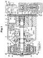
- Figure 1 is a cross-sectional view of a variable displacement compressor according to one embodiment of the present invention;
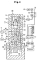
- Figure 2 is a cross-sectional view showing a displacement control valve incorporated in the compressor shown in Figure 1;
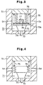
- Figure 3 is a cross-sectional view showing a part of the displacement control valve according to another embodiment; and
- Figure 4 is a cross-sectional view showing a part of the displacement control valve according to another embodiment.
-
- The present invention will be described by way of example referring to Figures 1 and 2.
- As shown in Figure 1, a swash plate compressor is provided with a
cylinder block 1, a front housing member 2 joined with the front end of thecylinder block 1, and a rear housing member 4 joined with the rear end of thecylinder block 1 through avalve plate 3. Thecylinder block 1, the front housing 2, thevalve plate 3 and the rear housing member 4 are held together with a plurality of through bolts (not shown) to form a compressor housing. - A
crank chamber 5 is defined between thecylinder block 1 and the front housing member 2. A drive shaft 6 is supported by thecylinder block 1 and the front housing member 2 with a plurality of radial bearings. - A bore housing a helical spring 7 and a thrust bearing 8 is formed substantially at the center of the
cylinder block 1. In thecrank chamber 5, a rotatingsupport 11 is fixed on the drive shaft 6 to rotate integrally with the drive shaft 6. Another thrust bearing 9 is located between therotating support 11 and an inner wall of the front housing member 2. The drive shaft 6 is urged toward the front housing member 2 by the spring 7. - The drive shaft 6 is connected through an electromagnetic clutch 40 to an engine E, which serves as an external power source. The
electromagnetic clutch 40 includes apulley 42, anannular solenoid coil 43 and anarmature 45. Thepulley 42 is supported by a bearing 41 at the front end of the front housing member 2. Thearmature 45 is connected to the drive shaft 6 by aleaf spring 44. - When electric current is supplied to the
coil 43, electromagnetic attraction is produced between thearmature 45 and thepulley 42, which causes thearmature 45 to engage thepulley 42, as shown in Figure 1. consequently, the driving power of the engine E is transmitted to the drive shaft 6 through atransmission belt 46, thepulley 42, thearmature 45 and theleaf spring 44. When the supply of electric current to thecoil 43 is interrupted, thearmature 45 is separated from thepulley 42 by the force of theleaf spring 44 to interrupt the power transmission. Thus, the driving power of the engine E can be transmitted to the drive shaft 6 selectively by controlling the supply of electric current to thecoil 43. - A
swash plate 12, or drive plate, is housed in thecrank chamber 5. The drive shaft 6 passes through a hole formed at the center of theswash plate 12. Theswash plate 12 is connected through ahinge mechanism 13 to therotating support 11 and the drive shaft 6. Thehinge mechanism 13 consists essentially of a supportingarm 14 provided on therotating support 11, and aguide pin 15 with a spherical head. The supportingarm 14 has a generally cylindrical socket for supporting the spherical head. Thehinge mechanism 13 causes theswash plate 12 and the drive shaft 6 to rotate together and permits theswash plate 12 to move in the axial direction of the drive shaft 6, along the surface of the drive shaft 6, and to incline with respect to the axis of the drive shaft 6. - A
coil spring 16 is fitted to the drive shaft 6 between therotating support 11 and theswash plate 12. Thespring 16 urges theswash plate 12 in a direction to decrease the angle of inclination of the swash plate 12 (as measured with respect to a plane perpendicular to the axis of the drive shaft 6). Asnap ring 17 is fixed on the drive shaft 6 between theswash plate 12 and thecylinder block 1. Thesnap ring 17 restricts the movement of theswash plate 12 in the direction of the rear housing member 4 to determine the minimum inclination angle of theswash plate 12. The minimum inclination angle is, for example, 3 to 5 degrees. The maximum inclination angle of theswash plate 12 is determined by the abutment of acounterweight 12a formed on theswash plate 12 against a restrictingsection 11a of therotating support 11. - A plurality of cylinder bores 1a (only one bore is shown) are defined in the
cylinder block 1. The cylinder bores 1a are arranged at predetermined angular intervals along a circle drawn about the axis of the drive shaft 6. A single-headedpiston 18 is located in eachcylinder bore 1a. Eachpiston 18 is connected to theswash plate 12 through a pair ofshoes 19. - A
suction chamber 21, the pressure of which is referred to as the suction pressure Ps, and adischarge chamber 22, the pressure of which is referred to as the discharge pressure Pd, are defined in the rear housing member 4. Thevalve plate 3 contains asuction port 23, asuction valve 24, adischarge port 25 and adischarge valve 26 for eachcylinder bore 1a. Thesuction chamber 21 communicates with each cylinder bore 1a through thesuction port 23. Eachcylinder bore 1a communicates with thedischarge chamber 22 through thedischarge port 25. - In the swash plate type compressor shown in Figure 1, the drive shaft 6 is rotated when the engine E is driven, and the
swash plate 12 rotates with the rotation of the shaft 6. The rotational movement of theswash plate 12 is converted through theshoes 19 into reciprocating movement of thepistons 18. This reciprocating movement compresses a coolant gas drawn from thesuction chamber 21, through thevalve plate 3, into eachcylinder bore 1a. Compressed coolant gas is exhausted from each cylinder bore 1a into thedischarge chamber 22. - The inclination angle of the
swash plate 12 is determined according to various moments applied to theswash plate 12. The moments include a rotational moment, which is based on the centrifugal force of therotating swash plate 12, a spring force moment, which is based on the force of thespring 16, and a gas pressure moment, which is based on the net force applied to eachpiston 18 by gas pressure. The rotational moment acts on theswash plate 12 to increase the inclination angle. The gas pressure moment depends on the reactive force of compression acting upon thepistons 18 during the compressing strokes, the internal pressure of thecylinder bore 1a acting upon thepistons 18 during the suction strokes, and the pressure of the crank chamber 5 (crank pressure Pc). The gas pressure moment acts on theswash plate 12 to decrease the inclination angle. - In this embodiment, when the crank pressure Pc is maintained at a relatively high level, the sum of the gas pressure moment and the spring force moment is greater than the rotational moment. Accordingly, the
swash plate 12 tends to shift to the minimum inclination angle position. The sum of the moment based on the gas pressure and the moment based on the spring force is balanced with the moment of the rotational movement by adjusting the crank pressure Pc. Thus, the inclination of theswash plate 12 can be set at a desired angle between the minimum inclination angle position and the maximum inclination angle position. The stroke of eachpiston 18, or the discharge displacement of the compressor, is adjusted according to the inclination angle of theswash plate 12. - As shown in Figures 1 and 2, the mechanism for controlling the crank pressure Pc consists essentially of a
displacement control valve 50 and a plurality ofpassages bleed passage 27 connecting thecrank chamber 5 to thesuction chamber 21, and asupply passage 28 connecting thecrank chamber 5 to thedischarge chamber 22. Thecontrol valve 50 is located in thebleed passage 27 and thesupply passage 28. Thevalve 50 can regulate the flow in thesepassages control valve 50 and thecrank chamber 5 serves both as part of thebleed passage 27 and part of thesupply passage 28 and is therefore referred to as a common passage 90. - The portion of the
bleed passage 27 connecting thecontrol valve 50 to thesuction chamber 21 functions also as a pressure detecting passage for applying the suction pressure Ps to thecontrol valve 50. Further, the compressor housing is provided with, in addition to thesupply passage 28, anauxiliary supply passage 29 connecting thecrank chamber 5 to thedischarge chamber 22. Theauxiliary supply passage 29 is provided with a fixedrestriction 29a. - The
discharge chamber 22 and thesuction chamber 21 are connected to each other through an externalrefrigerant circuit 30. The externalrefrigerant circuit 30 formes, together with the compressor, a cooling circuit of an air conditioner. The externalrefrigerant circuit 30 is provided with acondenser 31, athermostatic expansion valve 32 and anevaporator 33. The valve position of theexpansion valve 32 is feedback-controlled based on the temperature detected by a temperature detecting cylinder located at the outlet of theevaporator 33. The outlet temperature of theevaporator 33 reflects the thermal load applied to the refrigerator circuit. Theexpansion valve 32 supplies an appropriate amount of coolant to theevaporator 33 depending on the thermal load applied to the refrigerator circuit. This adjusts the flow rate of the coolant in the externalrefrigerant circuit 30. - As shown in Figure 2, a
temperature sensor 34 is located adjacent to theevaporator 33. Thetemperature sensor 34 detects the temperature of theevaporator 33 and outputs a signal indicating the detection result to a controller C. The controller C is a computer that performs overall control of heating and cooling for a vehicle passenger compartment. Acabin temperature sensor 35 for detecting the temperature in the passenger compartment, acabin temperature setter 36 for setting the target temperature in the passenger compartment, anactuating switch 37 and an enginerevolution speed sensor 38 are connected to the inlet side of the controller C along with thetemperature sensor 34. Adrive circuit 39A for controlling the supply of electric current to thesolenoid coil 43 of theelectromagnetic clutch 40 and anotherdrive circuit 39B for controlling the supply of electric current to a coil 85 (to be described later) of thecontrol valve 50 are connected to the output side of the controller C. - The controller C controls the
electromagnetic clutch 40 and thecontrol valve 50 based on various information including the temperature of theevaporator 33 detected by thetemperature sensor 34, the temperature detected by thecabin temperature sensor 35, the target temperature set by thecabin temperature setter 36, the position of theswitch 37, and the engine speed from the enginerevolution speed sensor 38. The controller C computes the value of electric current to be supplied to thecoil 85 of thecontrol valve 50 based on the received information and instructs thedrive circuit 39B accordingly. - As shown in Figure 2, the
control valve 50 is provided with afirst valve mechanism 60 for selectively opening and closing thesupply passage 28, asecond valve mechanism 70 for adjusting the opening size of the thebleed passage 27, and asolenoid mechanism 80 connected to the twovalve mechanisms mechanisms valve housing 51. Thefirst valve mechanism 60 and thesecond valve mechanism 70 can be operated independently as will be described later. - The
first valve mechanism 60 is provided with afirst valve chamber 61 and an axial passage 62 defined in thevalve housing 51. Thefirst valve chamber 61 communicates with thedischarge chamber 22 through asupply port 52 and thesupply passage 28. The pressure of the discharge chamber 22 (discharge pressure Pd) is applied to thefirst valve chamber 61. A linear passage, or the axial passage 62 is connected with thecrank chamber 5 through a common port 53 and the common passage 90, and the crank pressure Pc is applied to the axial passage 62. The portion of the axial passage 62 opening to thefirst valve chamber 61 constitutes afirst valve opening 63. Thefirst valve chamber 61, the axial passage 62 and thefirst valve opening 63 form a part of thesupply passage 28. - A
first valve element 64 is located in thefirst valve chamber 61 to move in the axial direction of thecontrol valve 50. Thefirst valve element 64 opens and closes thefirst valve opening 63. Thefirst valve element 64 is connected to afirst plunger 82 through afirst rod 65. Thefirst plunger 82 is located in asolenoid chamber 81 located adjacent to thefirst valve chamber 61. Anopening spring 66 is located between thefirst valve element 64 and the inner wall of thefirst valve chamber 61. Theopening spring 66 urges thefirst valve element 64 away from thefirst valve opening 63, so thefirst valve mechanism 60 is normally open. Thefirst valve element 64, thefirst rod 65 and thefirst plunger 82 constitute an integral body, and the integral body has anaxial hole 67. The cross-sectional area S1 of thefirst rod 65 is substantially equal to the cross-sectional area S2 of thefirst valve opening 63. - The
second valve mechanism 70 is provided with a pressure chamber, or asecond valve chamber 71, defined above and adjacent to the axial passage 62 in thevalve housing 51. Thesecond valve chamber 71 functions as a pressure detecting chamber. Thesecond valve chamber 71 communicates with thesuction chamber 21 through aport 54 and the downstream part of the bleed passage (pressure detecting passage) 27. Accordingly, the pressure of the suction chamber 21 (suction pressure Ps) is applied to thesecond valve chamber 71. - The
second valve chamber 71 has an annular spring seat 55 extending from the inner circumferential wall of thevalve housing 51. The spring seat 55 divides thesecond valve chamber 71 into an upper region and a lower region. However, these two regions communicate with each other through a center hole in the spring seat 55, and they have the same pressure. The portion of the axial passage 62 opening to thesecond valve chamber 71 constitutes a taperedsecond valve opening 72. The axial passage 62, thesecond valve chamber 71 and the second valve opening 72 form part of thebleed passage 27. - A
second valve element 73 is located in thesecond valve chamber 71 to be movable in the axial direction of thecontrol valve 50. Thesecond valve element 73 varies the area of the second valve opening 72 that is available for gas flow. The lower end of thesecond valve element 73 is connected to asecond plunger 83 through asecond rod 74. Thesecond plunger 83 is housed in thesolenoid chamber 81. Thesecond rod 74 extends through the axial passage 62 and thefirst valve chamber 61 and into thesolenoid chamber 81. Thesecond rod 74 is fitted in theaxial hole 67 of thefirst rod 65. A closingspring 75 is located between thesecond valve element 73 and the spring seat 55. The closingspring 75 urges thesecond valve element 73 toward the second valve opening 72 to normally close thesecond valve opening 72. - A bellows 76, which serves as a pressure sensing member, is also located in the
second valve chamber 71. One end (the upper end in the drawings) of thebellows 76 is fixed to the wall of thevalve chamber 71, and a connectingcylinder 77 is fixed to the other end. Thesecond valve element 73 is fixed to apressure detecting rod 78, and the upper end of thepressure detecting rod 78 is inserted into the connectingcylinder 77. Thepressure detecting rod 78 is not fixed to the connectingcylinder 77 and is movable relative to the connectingcylinder 77. The bellows 76 is connected to thesecond valve element 73 and moves toward and away from thesecond valve element 73. The bellows 76 expands and contracts depending on the suction pressure Ps, which is applied to thesecond valve chamber 71, which causes thesecond valve element 73 to change the effective size of thesecond valve opening 72. - The
solenoid mechanism 80 includes asolenoid chamber 81 defined in thevalve housing 51. When thecontrol valve 50 is attached to the rear housing member 4 of the compressor, anannular chamber 56 is defined between thevalve housing 51 and an inner surface of the rear housing member 4 at a position corresponding to the location of the common port 53. Thevalve housing 51 contains apressure application passage 57 formed to connect theannular chamber 56 and thesolenoid chamber 81. The crank pressure Pc is applied through theannular chamber 56 and thepressure application passage 57 to thesolenoid chamber 81. - A fixed
iron core 84 is located between thesolenoid chamber 81 and thefirst valve chamber 61. Thesolenoid chamber 81 contains thefirst plunger 82 and thesecond plunger 83. Acoil 85 is wound around the fixediron core 84 to surround theplungers coil 85 is controlled by the controller C. The electromagnetic force generated by energization of thecoil 85 urges theplungers iron core 84 against the forces of thesprings coil 85, the force of thefirst plunger 82 toward the fixediron core 84 overcomes the force of theopening spring 66 to fully close thefirst valve mechanism 60. On the contrary, if no electric current is supplied to thecoil 85, thefirst valve mechanism 60 is fully opened. Accordingly, thefirst valve mechanism 60 is opened and closed selectively by external control. Thesecond valve mechanism 70 adjusts the effective size of thevalve opening 72 depending on the level of electric current supplied to thecoil 85 and the suction pressure Ps. - The operation of the variable displacement compressor of Figs 1 and 2 will now be described.
- When the
actuating switch 37 is turned off, theelectromagnetic clutch 40 is disengaged, and the compressor is inoperative. At this time, no electric current is supplied to thecoil 84 of thecontrol valve 50, and thus no electromagnetic force is applied to theplungers first valve mechanism 60, thefirst valve opening 63 is opened fully by theopening spring 66, and in thesecond valve mechanism 70, the second valve opening 72 is closed by the closingspring 75. If the inoperative state of the compressor continues for a relatively long time, the internal pressures of thechambers swash plate 12 is maintained at the minimum inclination by thespring 16. - If the cabin temperature detected by the
cabin temperature sensor 35 exceeds the temperature preset by thecabin temperature setter 36 when theactuating switch 37 is turned on, the controller C energizes thesolenoid coil 43 of theelectromagnetic clutch 40. Thus, the engine E drives the compressor. Simultaneously, the controller C energizes thecoil 85 of thecontrol valve 50. This causes the fixediron core 84 to electromagnetically attract thefirst plunger 82, and thefirst valve element 64 closes the first valve opening 63 against the force of the opening spring 66 (see Figure 2) and fully closes thesupply passage 28. - An electromagnetic force corresponding to the level of electric current is generated between the
first plunger 82 and thesecond plunger 83 by the energization of thecoil 85. This electromagnetic attractive force is transmitted through thesecond rod 74 to thesecond valve element 73, which increases the effective size of the second valve opening 72 against the force of theclosing spring 75. As long as thecoil 85 is magnetized, a connection is established among thesecond plunger 83, thesecond valve element 73 and thebellows 76. The force of thebellows 76 depends on the fluctuation of the suction pressure Ps, which is applied to thesecond valve chamber 71, and affects the position of thesecond valve element 73. In other words, thesecond valve mechanism 70 determines the effective size of thevalve opening 72 based on the balance of the electromagnetic force applied to thesecond plunger 83, the force of theclosing spring 75, and the force of thebellows 76, which reflects the suction pressure Ps. Thus, thefirst valve element 64 and thesecond valve element 73 operate independently even when thecoil 85 is energized. - As the thermal load increases, the outlet pressure of the evaporator 33 (i.e., suction pressure Ps) increases gradually, and the difference between the temperature detected by the
cabin temperature sensor 35 and the temperature preset by thecabin temperature setter 36 also increases. When this occurs, the controller C controls the value of electric current supplied to thecoil 85 based on the detected cabin temperature and the preset cabin temperature. More specifically, the supply of electric current is increased as the detected cabin temperature increases, and the force applied to thesecond valve element 73 is increased in the direction of increasing the effective size of thesecond valve opening 72. This has the effect of reducing the suction pressure Ps. That is, the increase in the electric current level supplied to thecoil 85 causessecond valve mechanism 70 to decrease the suction pressure Ps. In other words, thesecond valve mechanism 70 determines a target value of the suction pressure Ps depending on the level of electric current supplied to thecoil 85. - The greater the effective size of the second valve opening 72, the greater the flow rate of gas from the
crank chamber 5 through thebleed passage 27 to thesuction chamber 21. Meanwhile, gas cannot flow from thedischarge chamber 22 through thesupply passage 28 into thecrank chamber 5, since thefirst valve mechanism 60 is closed. Therefore, the crank pressure Pc drops. Further, when there is a great thermal load, the pressure of the gas drawn into the cylinder bores 1a, or suction pressure Ps, is relatively high, and the difference between the internal pressure of the cylinder bores 1a and the crank pressure Pc becomes small. Accordingly, the inclination angle of theswash plate 12 increases to increase the discharge displacement of the compressor. As a result, the suction pressure Ps is lowered gradually. - When the effective size of the second valve opening 72 is maximized, a maximum amount of gas flows from the
crank chamber 5 through thebleed passage 27 to thesuction chamber 21. The crank pressure Pc then falls to approximately the pressure in the suction chamber 21 (suction pressure Ps), and the inclination of theswash plate 21 reaches the maximum angle, which results in the maximum discharge displacement. In the maximum discharge displacement state, fluctuation in the condensation capacity in thecondenser 31 can increase the pressure in the discharge chamber 22 (discharge pressure Pd) greatly. In this state, the relatively high discharge pressure Pd is applied to thefirst valve chamber 61 and thefirst valve element 64. - However, the cross-sectional area S1 of the
first rod 65 connecting thefirst valve element 64 to thefirst plunger 82 is substantially equal to the cross-sectional area S2 of thefirst valve opening 63. Therefore, the pressure-receiving areas on both ends of thefirst valve element 64 are almost equal when thefirst valve element 64 closes thefirst valve opening 63. Consequently, the forces acting on thefirst valve element 64 in its moving direction substantially offset each other, which allows the first valve element to be smoothly operated without being affected by the discharge pressure Pd and the crank pressure Pc. - As the thermal load decreases, the outlet pressure of the
evaporator 33 is lowered gradually, and the difference between the temperature detected by thecabin temperature sensor 35 and the temperature preset by thecabin temperature setter 36 becomes small. Therefore, the controller C controls the level of the electric current supplied to thecoil 85 to optimize the discharge capacity of the compressor for the thermal load. More specifically, the level of the electric current is reducd as the detected cabin temperature is lowered and the force of thesecond valve element 73 in the direction to increase the effective size of the second valve opening 72 is reduced. This has the effect of increasing the suction pressure Ps. That is, the reduction in the level of the electric current supplied to thecoil 85 causes thesecond valve mechanism 70 to maintain the suction pressure Ps at a higher value. - The smaller the effective size of the second valve opening 72, the smaller the flow rate of gas from the
crank chamber 5 through thebleed passage 27 to thesuction chamber 21, which increases the crank pressure Pc. Further, when there is a small thermal load, the pressure of the gas drawn into thecylinder bore 1a, or the suction pressure Ps, is relatively low, and the difference between the internal pressure of thecylinder bore 1a and the crank pressure Pc becomes great. Accordingly, the inclination angle of theswash plate 12 decreases, which reduces the discharge displacement. As a result, the suction pressure Ps is increased gradually. - When the thermal load is approximately nil, the temperature of the
evaporator 33 drops gradually toward the temperature at which frosting occurs. If the temperature detected by thetemperature sensor 34 drops to a preset level (a temperature at which frosting can occur in the evaporator 33) or lower, the controller C interrupts the supply of electric current to thecoil 85. This causes the electromagnetic attraction between the fixediron core 84 and the first plunger and that between thefirst plunger 82 and thesecond plunger 83 to disappear. Accordingly, thefirst valve mechanism 60 fully opens thesupply passage 28 under the force of theopening spring 66, while thesecond valve mechanism 70 closes thebleed passage 27 under the force of theclosing spring 75. As a result, the high-pressure gas in thedischarge chamber 22 is supplied in a large amount through thesupply passage 28 into thecrank chamber 5 to increase the crank pressure Pc. Consequently, theswash plate 12 shifts to the minimum inclination angle position, which minimizes the cooling capacity of the air conditioner. - When the
actuating switch 37 is turned off, the controller C interrupts energization of thecoil 85 to shift theswash plate 12 to the minimum inclination angle position. - The
pressure detecting rod 78 and the connectingcylinder 77 of the bellows are not fixed and are thus able to move relative to each other. The closingspring 75 constantly urges thesecond valve element 73 away from thebellows 76. When the bellows 76 contracts, due to an increase in the suction pressure Ps, while thesolenoid mechanism 80 is de-energized, the connectingcylinder 77 moves relative to the pressure detecting rod. Accordingly, the upward movement of thebellows 76 is not transmitted to thesecond valve element 73. Therefore, even if the suction pressure Ps increases when thesolenoid mechanism 80 is de-energized, thesecond valve mechanism 70 keeps the second valve opening 72 closed. - If the temperature of the passenger compartment (thermal load) increases when the
actuating switch 37 is turned on and theswash plate 12 is at the minimum inclination position, the temperature of the passenger compartment detected by thecabin temperature sensor 35 exceeds the temperature preset by thecabin temperature setter 36. In response, the controller C outputs a command to energize thesolenoid mechanism 80 according to the change in the temperature. With the activation of thesolenoid mechanism 80, thefirst valve mechanism 60 closes thesupply passage 28, while thesecond valve mechanism 70 opens thebleed passage 27 to reduce the crank pressure Pc gradually and to increase the angle of inclination of theswash plate 12. - As described above, the actions of the
first valve mechanism 60 and those of thesecond valve mechanism 70 are controlled by supply and interruption of electric current to thecoil 85 of thesolenoid mechanism 80. In particular, thesecond valve mechanism 70 can vary the target value of the suction pressure Ps by controlling the level of the electric current supplied to thecoil 85. Thus, the controller can change the displacement by changing the inclination angle of theswash plate 12 so that the actual suction pressure Ps will approach the target value. - This embodiment has the following effects.
- The
displacement control valve 50 includes thefirst valve mechanism 60 for selectively opening and closing thesupply passage 28 and thesecond valve mechanism 70 for adjusting the opening size of thebleed passage 27 in onevalve housing 51. This miniaturizes, simplifies, and reduces the cost of the mechanism for controlling the displacement of the compressor compared to the employment of two independent valve mechanisms. Miniaturizing the displacement control mechanism results in a smaller compressor. - Since a
single coil 85 is used with thefirst plunger 82 of thefirst valve mechanism 60 and thesecond plunger 83 of thesecond valve mechanism 70, the structure of thecontrol valve 50 is simplified. - The
second rod 74 connecting thesecond valve element 73 and thesecond plunger 83 passes through the integral body, which includes thefirst valve element 64, theplunger 82 and thefirst rod 65. This reduces the size of thecontrol valve 50 in the axial direction. - The
solenoid mechanism 80 is located at one end of thevalve housing 51. As shown in Figure 1, when thecontrol valve 50 is incorporated into the rear housing member 4 of the compressor, part of thesolenoid mechanism 80 is exposed. This facilitates the connection of wiring to thecoil 85. - The
second valve element 73 and thebellow 76 are located in asingle chamber 71, to which the suction pressure Ps is applied. This reduces the number of chambers to be formed in thecontrol valve 50 and simplifies thecontrol valve 50. Further, if a second valve element and a bellows were located in different chambers and connected with a pressure detecting rod, as in the control valve disclosed in Japanese Unexamined Patent Publication No. 10-103249, high-accuracy machining would be required to avoid a clearance between the diaphragm located between these two chambers and the pressure detecting rod, which would pass through the diaphragm. This construction is disadvantageous in terms of ease of manufacture and cost. However, thecontrol valve 50 of this embodiment, which has both thesecond valve element 73 and thebellows 76 in thesame chamber 71, overcomes the problems inherent in the control valve disclosed in Japanese Unexamined Patent Publication No. 10-103249. - In the outlet control method where the inclination angle of the
swash plate 12 is adjusted by controlling the amount of gas exhausted from thecrank chamber 5, high-pressure coolant gas must be supplied constantly to the crankchamber 5 to change the inclination angle of theswash plate 12 responsively. The variable displacement compressor shown in Figure 1 has theauxiliary supply passage 29 connecting thedischarge chamber 22 to the crankchamber 5, and theauxiliary supply passage 29 has the fixedrestriction 29a. Accordingly, when thesupply passage 28 is closed by thefirst valve mechanism 60 and the opening of thebleed passage 27 is regulated by thesecond valve mechanism 70, a predetermined amount of coolant gas is supplied constantly from thedischarge chamber 22 to the crankchamber 5 through theauxiliary supply passage 29 to the crankchamber 5. Thus, the crank pressure Pc is maintained constantly at a predetermined value or higher, and thus the swash plate 12 (or the discharge displacement of the compressor) responds rapidly to changes. - The embodiment of Figs 1 and 2 may be modified as follows.
- The
second valve chamber 71, or thepressure detecting chamber 71, may be constructed as shown in Figures 3 or 4. In Figure 3, the length of thepressure detecting rod 78 is shorter than in Figure 2. Further, the closingspring 75 is located between the wall of thesecond valve chamber 72 and aspring seat 73a formed at the head of thesecond valve element 73. Here, thepressure detecting rod 78 is loosely fitted in the connectingcylinder 77, as in thecontrol valve 50 shown in Figure 2. - In Figure 4, the closing
spring 75 is located between the wall of thevalve chamber 71 and the upper end of thebellows 76. Further, thesecond valve element 73 is fixed to the other end of thebellows 76. If the construction of thesecond valve chamber 71 in thecontrol valve 50 shown in Figure 2 is changed as shown in Figure 3 or 4, the operation of thecontrol valve 50 is the same. - The arrangement of the
second rod 74 and that of thefirst rod 65 in the control valve shown in Figure 2 may be reversed. That is, thesecond rod 74 may be formed to have tubular structure, and thefirst rod 65 may be fitted inside thesecond rod 74 such that the rods are movable relative to each other. - The pressure detector employed in the
second valve mechanism 70 is limited to the bellows but may be, for example, a diaphragm. - In the embodiments shown in Figures 2 and 3, the
pressure detecting rod 78 and the connectingcylinder 77 may be fixed to each other. - The
displacement control valve 50 may be applied to a clutchless variable displacement compressor (constantly driven compressor). - The present examples and embodiments are to be considered as illustrative and not restrictive, and the invention is not to be limited to the details given herein, but may be modified within the scope and equivalence of the appended claims.
- A displacement control valve adjusts the pressure in a crank chamber (5) of a compressor to vary the displacement of the compressor. The control valve has a first valve mechanism (60), a second valve mechanism (70) and a solenoid mechanism (80). The solenoid mechanism (80) independently actuates the first and second valve mechanisms (60, 70). The first valve mechanism (60) selectively opens and closes a supply passage (28) of the compressor. The second valve mechanism (70) adjusts the flow rate of gas through a bleed passage (27) of the compressor. The second valve mechanism (70) includes a second valve opening (72), a second valve element (73), a bellows (76) and a second plunger (83). The second valve element (73) and the bellows (76) are accommodated in a single pressure chamber (71). The pressure of a suction chamber is introduced to the pressure chamber (71). The control valve has a relatively simple structure and is thus inexpensive and compact.
Claims (13)
- A control valve for a variable displacement compressor, wherein the control valve adjusts the pressure in a crank chamber (5) of the compressor to vary the compressor displacement, wherein the compressor includes a suction pressure zone (21), the pressure of which is a suction pressure, a discharge pressure zone (22), the pressure of which is a discharge pressure, a bleed passage (27) for connecting the crank chamber (5) to the suction pressure zone (21), and a supply passage (28) for connecting the crank chamber (5) to the discharge pressure zone (22), the control valve comprising:a housing (51);a first valve mechanism (60) retained in the housing (51) to selectively open and close the supply passage (28), wherein the first valve mechanism (60) includes:a first valve opening (63) defined in the housing (51), the first valve opening (63) forming part of the supply passage (28);a first valve element (64) for selectively opening and closing the first valve opening (63); anda first plunger (82) connected to the first valve element (64);a second valve mechanism (70) retained in the housing (51) to adjust the flow rate of gas released from the crank chamber (5) to the suction pressure zone (21) through the bleed passage (27), wherein the second valve mechanism (70) includes:a second valve opening (72) defined in the housing (51), the second valve opening (72) forming part of the bleed passage (27);a second valve element (73) for adjusting the opening size of the second valve opening (72);a pressure sensing member (76) for moving the second valve element (73) in accordance with the suction pressure; anda second plunger (83) connected to the second valve element (73), wherein the first valve mechanism (60) and the second valve mechanism (70) operate independently;a solenoid mechanism (80) retained in the housing (51) to independently actuate the first valve mechanism (60) and the second valve mechanism (70), wherein the solenoid mechanism (80) includes a coil (85), and current supplied to the coil (85) produces an electromagnetic force for independently biasing the first and second plungers (82, 83) in accordance with the level of the current, the control valve being characterized by:a pressure chamber (71) defined in the housing (51) to accommodate the second valve element (73) and the pressure sensing member (76), wherein the pressure chamber (71) is exposed to the suction pressure.
- The control valve according to claim 1 characterized in that the first valve mechanism (60) includes an opening spring (66) for urging the first valve element (64) away from the first valve opening (63), and the second valve mechanism (70) includes a closing spring (75) for urging the second valve element (73) toward the second valve opening (72), and wherein, when current is supplied to the coil (85), the first plunger (82) causes the first valve element (64) to close the first valve opening (63) against the force of the opening spring (66) and the second plunger (83) urges the second valve element (73) away from the second valve opening (72) by a force corresponding to the level of the current.
- The control valve according to claims 1 or 2 characterized in that the pressure chamber (71) is located in the bleed passage (27) and the second valve opening (72) opens to the pressure chamber (71).
- The control valve according to any one of claims 1 to 3 characterized by a first rod (64) coupling the first valve element (64) with the first plunger (82) and a second rod (74) coupling the second valve element (73) with the second plunger (83), wherein one of the first rod (64) and the second rod (74) is fitted in the other, such that the first and second rods (65, 74) are axially movable relative to one another.
- The control valve according to claim 4 characterized in that the first and second valve openings (63, 72) are located at the ends of a linear passage (62) defined in the housing (51), and wherein the second rod (74) is fitted in the first rod (64) and extends through the linear passage (62).
- The control valve according to any one of claims 1 to 5 characterized in that the second valve element (73) is coupled to the pressure sensing member (76) such that the second valve element (73) is movable relative to the pressure sensing member (76).
- The control valve according to any one of claims 1 to 3 characterized by a first valve chamber (61) located in the supply passage (28) to accommodate the first valve element (64) and a first rod (64) that connects the first valve element (64) with the first plunger (82), wherein the first valve opening (63) opens to the first valve chamber (61) and is located at an opposite side of the first valve element (64) from the first rod (64), and wherein the cross sectional area of the first rod (64) is substantially equal to the cross sectional area of the first valve opening (63).
- The control valve according to claim 7 characterized in that the first valve opening (63) is connected to the crank chamber (5) by the supply passage (28) and wherein the first valve chamber (61) is connected to the discharge pressure zone (22) by the supply passage (28).
- The control valve according to claim 8 characterized by a solenoid chamber (81) to accommodate the first and second plungers (82, 83) and a pressure application passage (57) for applying the pressure in the crank chamber (5) to the solenoid chamber (81).
- A compressor having the control valve according to any one of claims 1 to 9.
- The compressor according to claim 10 characterized by an auxiliary supply passage (29) connecting the crank chamber (5) with the discharge pressure zone (22), wherein the auxiliary supply passage (29) includes a fixed restriction (29a).
- The compressor according to claims 10 or 11 characterized in that a downstream part of the supply passage (28) also serves as an upstream part of the bleed passage (27).
- The compressor according to any one of claims 10 to 12 characterized in that the compressor is coupled to an external power source (E), and a clutch (40) is located between the external power source (E) and the compressor to selectively engage the external power source (E) with the compressor.
Applications Claiming Priority (2)
| Application Number | Priority Date | Filing Date | Title |
|---|---|---|---|
| JP02144099A JP3899719B2 (en) | 1999-01-29 | 1999-01-29 | Control valve for variable capacity compressor |
| JP2144099 | 1999-01-29 |
Publications (2)
| Publication Number | Publication Date |
|---|---|
| EP1024286A2 true EP1024286A2 (en) | 2000-08-02 |
| EP1024286A3 EP1024286A3 (en) | 2001-02-07 |
Family
ID=12055036
Family Applications (1)
| Application Number | Title | Priority Date | Filing Date |
|---|---|---|---|
| EP00101797A Withdrawn EP1024286A3 (en) | 1999-01-29 | 2000-01-28 | Control valve for variable displacement compressor |
Country Status (2)
| Country | Link |
|---|---|
| EP (1) | EP1024286A3 (en) |
| JP (1) | JP3899719B2 (en) |
Cited By (7)
| Publication number | Priority date | Publication date | Assignee | Title |
|---|---|---|---|---|
| EP1179680A3 (en) * | 2000-08-08 | 2003-05-14 | Kabushiki Kaisha Toyota Jidoshokki | Control valve for a variable displacement swash plate compressor |
| EP1186778A3 (en) * | 2000-09-08 | 2004-01-02 | Kabushiki Kaisha Toyota Jidoshokki | Control valve for variable displacement type compressor |
| EP1586772A4 (en) * | 2002-12-27 | 2006-08-16 | Zexel Valeo Climate Contr Corp | Control device for variable capacity compressor |
| EP1764505A1 (en) * | 2005-09-14 | 2007-03-21 | Kabushiki Kaisha Toyoda Jidoshokki | Control valve for clutch type variable displacement compressor |
| EP1775470A4 (en) * | 2004-07-13 | 2007-08-08 | Sanden Corp | Capacity control valve for clutchless variable displacement swash plate-type compressor |
| CN104074722A (en) * | 2014-07-03 | 2014-10-01 | 太原太航科技有限公司 | Composite control electric control valve |
| CN111670304A (en) * | 2018-01-29 | 2020-09-15 | 株式会社不二工机 | Control valve for variable capacity compressor |
Families Citing this family (8)
| Publication number | Priority date | Publication date | Assignee | Title |
|---|---|---|---|---|
| JP4586221B2 (en) * | 1999-11-08 | 2010-11-24 | Nok株式会社 | Control valve |
| JP4056711B2 (en) | 2001-03-19 | 2008-03-05 | 日産自動車株式会社 | Voice recognition device |
| JP4195633B2 (en) * | 2002-04-25 | 2008-12-10 | サンデン株式会社 | Variable displacement compressor with displacement control valve |
| EP1589223B1 (en) * | 2003-01-22 | 2019-04-24 | Valeo Japan Co., Ltd. | Control valve of variable displacement compressor |
| JP4331667B2 (en) | 2004-10-22 | 2009-09-16 | 株式会社テージーケー | Control valve for variable capacity compressor |
| WO2013058598A2 (en) * | 2011-10-20 | 2013-04-25 | 학교법인 두원학원 | Control valve for compressor |
| JP2018066291A (en) * | 2016-10-18 | 2018-04-26 | サンデン・オートモーティブコンポーネント株式会社 | Control valve of variable capacity compressor |
| RU205108U1 (en) * | 2020-10-30 | 2021-06-28 | Федеральное государственное бюджетное образовательное учреждение высшего образования "Керченский государственный морской технологический университет" (ФГБОУ ВО "КГМТУ") | SAFETY VALVE FOR CANDLES OF MARINE AUTO FILTERS |
Citations (2)
| Publication number | Priority date | Publication date | Assignee | Title |
|---|---|---|---|---|
| JPH0599136A (en) | 1991-10-23 | 1993-04-20 | Sanden Corp | Variable capacity type swash plate type compressor |
| JPH10103249A (en) | 1996-07-31 | 1998-04-21 | Toyota Autom Loom Works Ltd | Control valve |
Family Cites Families (3)
| Publication number | Priority date | Publication date | Assignee | Title |
|---|---|---|---|---|
| DE69200356T2 (en) * | 1991-01-28 | 1995-02-16 | Sanden Corp | Swash plate compressor with a device for changing the stroke. |
| WO1996002751A1 (en) * | 1994-07-13 | 1996-02-01 | Kabushiki Kaisha Toyoda Jidoshokki Seisakusho | Swash plate variable displacement compressor |
| US6010312A (en) * | 1996-07-31 | 2000-01-04 | Kabushiki Kaisha Toyoda Jidoshokki Seiksakusho | Control valve unit with independently operable valve mechanisms for variable displacement compressor |
-
1999
- 1999-01-29 JP JP02144099A patent/JP3899719B2/en not_active Expired - Fee Related
-
2000
- 2000-01-28 EP EP00101797A patent/EP1024286A3/en not_active Withdrawn
Patent Citations (2)
| Publication number | Priority date | Publication date | Assignee | Title |
|---|---|---|---|---|
| JPH0599136A (en) | 1991-10-23 | 1993-04-20 | Sanden Corp | Variable capacity type swash plate type compressor |
| JPH10103249A (en) | 1996-07-31 | 1998-04-21 | Toyota Autom Loom Works Ltd | Control valve |
Cited By (8)
| Publication number | Priority date | Publication date | Assignee | Title |
|---|---|---|---|---|
| EP1179680A3 (en) * | 2000-08-08 | 2003-05-14 | Kabushiki Kaisha Toyota Jidoshokki | Control valve for a variable displacement swash plate compressor |
| EP1186778A3 (en) * | 2000-09-08 | 2004-01-02 | Kabushiki Kaisha Toyota Jidoshokki | Control valve for variable displacement type compressor |
| EP1586772A4 (en) * | 2002-12-27 | 2006-08-16 | Zexel Valeo Climate Contr Corp | Control device for variable capacity compressor |
| EP1775470A4 (en) * | 2004-07-13 | 2007-08-08 | Sanden Corp | Capacity control valve for clutchless variable displacement swash plate-type compressor |
| EP1764505A1 (en) * | 2005-09-14 | 2007-03-21 | Kabushiki Kaisha Toyoda Jidoshokki | Control valve for clutch type variable displacement compressor |
| CN104074722A (en) * | 2014-07-03 | 2014-10-01 | 太原太航科技有限公司 | Composite control electric control valve |
| CN104074722B (en) * | 2014-07-03 | 2016-03-09 | 太原太航科技有限公司 | A kind of motor-operated control valve combining control |
| CN111670304A (en) * | 2018-01-29 | 2020-09-15 | 株式会社不二工机 | Control valve for variable capacity compressor |
Also Published As
| Publication number | Publication date |
|---|---|
| JP3899719B2 (en) | 2007-03-28 |
| EP1024286A3 (en) | 2001-02-07 |
| JP2000220576A (en) | 2000-08-08 |
Similar Documents
| Publication | Publication Date | Title |
|---|---|---|
| US6361283B1 (en) | Displacement control valve | |
| EP1172559B1 (en) | Displacement control mechanism for variable displacement type compressor | |
| EP0848164B1 (en) | Control valve in variable displacement compressor | |
| US6062824A (en) | Control valve | |
| US5890876A (en) | Control valve in variable displacement compressor | |
| US6010312A (en) | Control valve unit with independently operable valve mechanisms for variable displacement compressor | |
| US6244159B1 (en) | Variable displacement type swash plate compressor and displacement control valve | |
| US6234763B1 (en) | Variable displacement compressor | |
| US6352416B1 (en) | Device and method for controlling displacement of variable displacement compressor | |
| US6398516B1 (en) | Variable displacement compressors and control valves for variable displacement compressors | |
| EP1081378A2 (en) | Control valve for variable displacement compressor | |
| EP0854288B1 (en) | Control valve in variable displacement compressor and method of manufacture | |
| EP1138946B1 (en) | Control valve for variable displacement compressor | |
| EP1024286A2 (en) | Control valve for variable displacement compressor | |
| EP1179680A2 (en) | Control valve for a variable displacement swash plate compressor | |
| US6589020B2 (en) | Control valve for variable displacement compressor | |
| US6783332B2 (en) | Control valve of variable displacement compressor with pressure sensing member | |
| EP1033489A2 (en) | Displacement control valve for variable displacement type compressors | |
| US6520749B2 (en) | Control valve for variable displacement compressor | |
| EP1070845A1 (en) | Crank pressure control mechanism of variable displacement compressor | |
| JPH10103249A (en) | Control valve | |
| JP3952425B2 (en) | Control valve for variable capacity compressor, variable capacity compressor, and method for assembling control valve for variable capacity compressor |
Legal Events
| Date | Code | Title | Description |
|---|---|---|---|
| PUAI | Public reference made under article 153(3) epc to a published international application that has entered the european phase |
Free format text: ORIGINAL CODE: 0009012 |
|
| 17P | Request for examination filed |
Effective date: 20000128 |
|
| AK | Designated contracting states |
Kind code of ref document: A2 Designated state(s): DE FR IT |
|
| AX | Request for extension of the european patent |
Free format text: AL;LT;LV;MK;RO;SI |
|
| PUAL | Search report despatched |
Free format text: ORIGINAL CODE: 0009013 |
|
| AK | Designated contracting states |
Kind code of ref document: A3 Designated state(s): AT BE CH CY DE DK ES FI FR GB GR IE IT LI LU MC NL PT SE |
|
| AX | Request for extension of the european patent |
Free format text: AL;LT;LV;MK;RO;SI |
|
| AKX | Designation fees paid |
Free format text: DE FR IT |
|
| STAA | Information on the status of an ep patent application or granted ep patent |
Free format text: STATUS: THE APPLICATION IS DEEMED TO BE WITHDRAWN |
|
| 18D | Application deemed to be withdrawn |
Effective date: 20020801 |