EP1032138A2 - Reception path search method and searcher circuit of cdma reception device - Google Patents
Reception path search method and searcher circuit of cdma reception device Download PDFInfo
- Publication number
- EP1032138A2 EP1032138A2 EP20000103400 EP00103400A EP1032138A2 EP 1032138 A2 EP1032138 A2 EP 1032138A2 EP 20000103400 EP20000103400 EP 20000103400 EP 00103400 A EP00103400 A EP 00103400A EP 1032138 A2 EP1032138 A2 EP 1032138A2
- Authority
- EP
- European Patent Office
- Prior art keywords
- addition
- delay profile
- phase
- subjected
- vector
- Prior art date
- Legal status (The legal status is an assumption and is not a legal conclusion. Google has not performed a legal analysis and makes no representation as to the accuracy of the status listed.)
- Granted
Links
Images


Classifications
-
- H—ELECTRICITY
- H04—ELECTRIC COMMUNICATION TECHNIQUE
- H04B—TRANSMISSION
- H04B1/00—Details of transmission systems, not covered by a single one of groups H04B3/00 - H04B13/00; Details of transmission systems not characterised by the medium used for transmission
- H04B1/69—Spread spectrum techniques
- H04B1/707—Spread spectrum techniques using direct sequence modulation
- H04B1/7097—Interference-related aspects
- H04B1/711—Interference-related aspects the interference being multi-path interference
- H04B1/7113—Determination of path profile
-
- H—ELECTRICITY
- H04—ELECTRIC COMMUNICATION TECHNIQUE
- H04B—TRANSMISSION
- H04B1/00—Details of transmission systems, not covered by a single one of groups H04B3/00 - H04B13/00; Details of transmission systems not characterised by the medium used for transmission
- H04B1/69—Spread spectrum techniques
- H04B1/707—Spread spectrum techniques using direct sequence modulation
- H04B1/7097—Interference-related aspects
- H04B1/711—Interference-related aspects the interference being multi-path interference
- H04B1/7115—Constructive combining of multi-path signals, i.e. RAKE receivers
- H04B1/7117—Selection, re-selection, allocation or re-allocation of paths to fingers, e.g. timing offset control of allocated fingers
Definitions
- the delay profile generator 2 inputs therein digitized complex base band signal inputted from the input terminal 1.
- the delay profile generator 2 executes inverse-diffusion of the complex base band signal in the well known signal list according to the means described in the list correlator of the second prior art or according to the appropriate known means. Subsequently, the delay profile generator 2 obtains the fading vector in every reception timing with required accuracy concerning required search range.
- the delay profile generator 2 generates to be outputted the delay profile of the vector value in every appropriate cycle, for instance, in every symbol cycle (STEP A2).
- the controller 8 obtains a power value of the fading vector in every respective reception timing in terms of the delay profile which is in-phase added until then, and which is maintained in the in-phase adder 6.
- the delay profile which is subjected to the power-addition is maintained in the power adder 7.
- the power value of the fading vector is added to the delay profile with the power-addition in every respective reception timing.
- the controller 8 controls the power adder 7 so as to update the delay profile which is power added according to addition between the power value of the fading vector and the power added delay profile (STEP A7).
- the in-phase added delay profile which is maintained in the in-phase adder 6 is eliminated.
- a delay profile D4 generated this time is maintained in the in-phase adder 6 newly as an in-phase added delay profile.
- the searcher circuit of the present invention causes the in-phase-addition of the delay profile and the number of the power-addition to be variable.
- the rotational comparator 5 obtains the angle difference between the basic vector and the fading vector which is subjected to weighted-averaging.
- angle variation of the phase angle of the reception complex base band signal is small. Therefore, it is judged that it is capable of improving S / N ratio of the delay profile effectively by virtue of the in-phase-addition to continue the in-phase-addition.
Abstract
Description
- The present invention relates to a reception path search method and searcher circuit for use in such method of a CDMA (Code Division Multiple Access) reception device.
- The CDMA communication system enables communication with high quality to be implemented under very low Eb / No (signal power in every 1 bit / noise power in every 1 Hz). The CDMA communication system is used in conjunction with diversity technique using multi-path propagation (RAKE), the technique of large error-correcting code of coding gain, transmission power control technique and so forth. The CDMA communication system in conjunction with the above techniques brings such high quality communication. In recent years, the CDMA communication is applied extensively in mobile communication and so forth.
- On the other hand, in the CDMA communication system, the reception signal is diffused using diffusion code. The diffused reception signal is subjected to inverse-diffusion by a diffusion code in the reception side. At the time of the inverse-diffusion of the diffused reception signal, chip timing (reception timing) of the diffusion code should be accurately synchronized with the reception signal diffused by using the diffusion code indispensably. Particularly, in the case of mobile communication, there exist a great many reception paths which are changed from moment to moment. In such the case, the most appropriate reception path should be selected regularly. Reception timing of respective reception paths is necessary to be synchronized with reception signal to be followed correctly.
- For instance, the Japanese Patent Application Laid-Open No. HEI 9-181704 (hereinafter referred to as a first prior art) discloses 'MULTIPATH SEARCH METHOD'. In the multipath search method, the CDMA reception device is provided with a set of search-finger and plural sets of tracking-fingers. The search-finger detects intensity level of reception signal concerning reception timing corresponding to delay range of the reception path supposed previously. The search-finger selects the most suitable plural reception paths to allocate plural reception paths to respective tracking-fingers. The tracking-finger tracks the respective reception paths in detail.
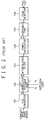
- Fig. 1 is a conception view showing basic operation of the above first prior art. Its (a) indicates a reception signal. The search-finger executes correlating detection with reception signal using diffusion code in which chip timing is changed gradually with information N symbol as search range. A delay profile with reception timing shown in (b) as the horizontal axis, and with intensity level of reception signal as the vertical axis is obtained. The intensity level of the reception signal is detected in such a way that the diffusion code is multiplied by the reception signal, before executing inverse-diffusion. Subsequently, such delay profile is integrated during fixed time by integrating-dump circuit. An amplitude square circuit executes amplitude square detection.
- A control means shown in (d) selects three reception paths in the example of Fig. 1, in order of the largeness of the maximum value of the delay profile. The control means allocates the chip timing to respective tracking-fingers.
- The tracking-finger shown in (c) executes inverse-diffusion of the reception signal using the diffusion code of each chip timing allocated previously to generate demodulating signal. The tracking-finger compares intensity of the reception signal which is subjected to inverse-diffusion using diffusion code whose chip phase is different by only ± Δ, namely, causing the chip timing to be moved before and after, thus tracking delay variation of the reception path using DLL (Delay Lock Loop).
- Furthermore, the search-finger continues search of the reception path periodically shown in (d). The reception path which is tracked by the tracking-finger overlaps with each other. When the reception path with large reception signal intensity level occurs by another cause. In such the cases, re-allocation of the reception path to the tracking-finger is implemented.
- In the first prior art, the demodulating signal outputted from respective tracking-fingers are obtained above such steps. Such the demodulating signal is detected to be demodulated with phase of pilot-symbol inserted in respective time slots of reception signal as a standard, thus the output signal is obtained by the fact that RAKE-composition is executed.
- It requires very large calculation quantity to obtain the delay profile while executing correlating detection with accuracy of 1/4 to 1/16 of the chip rate, for instance, in the above-described example, extending over wide search range such as extending over N symbols. For that reason, in the above-described first prior art, search of wide range according to the search-finger is restricted within fixed cycle. During this time interval, respective tracking-fingers monitor intensity level of the reception signal between two points with ± Δ, before executing tracking of the reception path.
- Furthermore, the official report of the Japanese Patent Application Laid-Open No. HEI 10-32523 (hereinafter referred to as a second prior art) discloses the technique for obtaining the delay profile with required accuracy. According to the technique, the reception signal undergoes sampling with relatively rough sampling frequency, for instance, a sampling frequency of 1/2 of the chip rate. It calculates mutual correlation between the diffusion code and, for instance, the known signal list obtained from the pilot symbol. The obtained correlation value of two samples per one chip is interpolated by an interpolation filter so that the delay profile with required accuracy is obtained.
- Fig. 2 is a block diagram showing a constitution of the searcher circuit of the second prior art. The searcher circuit of Fig. 2 comprises an A/
D converter 101 for converting a complex base band signal obtained from radio band signal into a digital reception signal S, alist correlator 102 for obtaining mutual correlation between the digital reception signal S and well known signal list about fixed search range in every fixed cycle, aninterpolation filter 103 for re-sampling an output signal R of thelist correlator 102 with four times of sampling frequency of for instance, the A/D converter 101, apower calculator 104 for obtaining power P of the mutual correlation signal which is re-executed sampling in theinterpolation filter 103, anaveraging part 105 for obtaining the delay profile while adding to be averaged a mutual correlation signal power P extending over plural cycles, and apeak detector 106 for determining the most suitable reception timing "τ opt" while obtaining peak "Popt" of the delay profile obtained by theaveraging part 105. - The digital reception signal S is indicated as time list data of complex number with in-phase component of the complex base band signal as real number part, and with orthogonal component as imaginary number part, namely as time list data of vector value.
- The
list correlator 102 calculates the mutual correlation value while multiplying the time list data by complex conjugate. - For instance, the sampling frequency of the A/
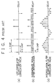
D converter 101 is taken as two times of the chip rate. As shown in Fig. 3, 1 time slot is constituted by transmission signal which consists of L symbols is diffused with a diffusion rate M (number of chip of diffusion code per 1 symbol) to be transmitted. On this occasion, signal component of symbol of m + 1 th order in a slot of n + 1 th order is diffused to the time list data from S ( - Consequently, from next formula, mutual correlation value Rnm (τ) with respect to symbol concerned is obtained as a vector value.
- Hereinafter, in the present specification, the mutual correlation value obtained by such procedure is represented as fading vector.
- In the second prior art, the fading vector is obtained concerning required search range
list correlator 102 of the slot in order of m + 1. - The
interpolation filter 103 obtains the profile with required delay precision by interpolating the profile of two times of the sample frequency of the chip rate obtained such procedure shown in Fig. 4. - In the example of Fig. 4, 0 vector is inserted in every 1/8 chip as shown in (b) into the fading vector in every 1/2 chip of the profile (a) outputted by the
list correlator 102. Thus, low pass filtering generates profile with accuracy of 8 times of the chip rate as shown in (c). The second prior art reduces required calculating quantity of thelist correlator 102 to about 1/4 thereof according to the above procedure. - According to such procedure, the delay profile of the vector value which is in-phase added in every respective slots can be obtained. However, the reception signal S is off concerning the phase between the slots. Therefore, it is incapable of improving S / N ratio (ratio of signal per noise) while executing the in-phase-addition, such that it is implemented to the adjacent pilot symbol.
- For that reason, the
interpolation filter 103 outputs chip rate. The delay profile has 1/8 precision of such chip rate. Thepower calculator 104 obtains a power value (square sum of in-phase component and orthogonal component) of the fading vector of respective reception timing inserted of such delay profile. Subsequently, thepower calculator 104 eliminates phase component. The averagingpart 105 executes the power-addition, namely the averagingpart 105 obtains mean value wile executing inter-slot addition of the power value of the same reception timing. The averagingpart 105 outputs the delay profile which is power-added while averaging dispersion according to noise or change according to fading. - The
peak detector 106 outputs one or plural reception timing "τ opt" which give the maximum value of the power added delay profile under such procedure. - As described above, in the case where the delay profile for searching the reception path of the CDMA reception device is obtained, in the conventional method, the fading vector is in-phase added with respect to fixed time interval when it can be thought that the phase of the reception complex base band signal does not change in large scale, for instance concretely, in the above second prior art, the fading vector is in-phase-added concerning the pilot signal of Np symbol added to the front of respective slots. The prior art procedure obtains the delay profile of the vector value, before executing the power-addition extending over appropriate cycle to obtain required delay profile.
- When change of transmission line of the reception path in between a plurality of delay profiles, namely radio band signal, is small, the suitable S / N ratio can be obtained using the in-phase-addition rather than the power-addition. However, in a practical manner, propagation characteristic of the transmission line changes from moment to moment.
- When the phase of the reception complex base band signal is changed according to change of the propagation characteristic of the transmission line, the phase of the fading vector is changed according thereto. In such the case, if the in-phase-addition continues, it is incapable of obtaining effective delay profile, since the meaningful signal component is cancelled caused by the vector-addition.
- Consequently, the conventional technique executes the in-phase-addition of the fading vector during fixed time interval uniformly to obtain the delay profile vector added, before power adding it to obtain the delay profile. Therefore, the conventional method has the problem that in the case where condition of the transmission line is changed largely as the mobile communication, it is not always obtained the effective delay profile.
- In view of the foregoing, it is an object of the present invention, in order to overcome the above mentioned problem, to provide a reception path search method and a searcher circuit for use in such method of a CDMA reception device which monitors change of phase angle of fading vector to judge propriety of continuity of the in-phase-addition. The reception path search method and a searcher circuit for use in such method of the CDMA reception device controls number of the in-phase-addition appropriately to obtain effective delay profile whose S / N ratio is suitable.
- According to a first aspect of the present invention, in order to achieve the above-mentioned object, there is provided a reception path search method of a reception device of CDMA (Code Division Multiple Access) communication system which comprises the steps of: generating a delay profile in every fixed cycle while executing plot of fading vector which is obtained in such a way that a reception signal converted into a complex base band signal is subjected to inverse-diffusion with known signal list in every reception timing about fixed range, generating an in-phase added delay profile while continuing vector-addition of the fading vector in every reception timing concerning continuous delay profile generated in every fixed cycle described above generating a power added delay profile while continuing the power-addition in every reception timing regarding fading vector with respect to continuous in-phase added delay profile, and searching an appropriate reception path while referring to the power added delay profile, wherein number of continuation of the vector-addition is taken to be variable, the reception path search method monitors a change of phase angle of the complex base band signal which change is reflected to respective delay profiles generated in every the fixed cycle, in the case where such phase angle is changed largely from settled angle of a threshold value, the reception path search method discontinues the continuation of the vector-addition, and then delay profiles which are in-phase added up to that time are taken as an object of the power-addition, before generating delay profile which is subjected to the power-addition.
- According to a second aspect of the present invention, there is provided a reception path search method of a reception device of CDMA (Code Division Multiple Access) communication system which comprises the steps of: a delay profile generating step for generating a delay profile in every fixed cycle in such a way that the reception path search method causes fading vector to be plotted in every reception timing in connection with a fixed range, such fading vector is obtained in such a way that reception signal converted into complex base band signal undergoes inverse-diffusion using known signal list, a fading vector averaging step for calculating fading vector which is subjected to weighted-averaging such that the reception path search method selects maximum value of prescribed number more than one in order of the largeness from among the fading vector plotted in every reception timing in connection with respective these delay profiles, before executing weighted-averaging, a rotational comparison step for comparing an absolute value of an angle difference between a phase angle of the fading vector which is subjected to weighted-averaging and a phase angle of a basic vector maintained separately with an angle of a threshold value determined beforehand, before replacing the basic vector with the fading vector which is subjected to weighted-averaging when the absolute value of the angle difference is larger than the angle of threshold value, an in-phase-addition step for updating a delay profile which is subjected to the in-phase-addition in such away that when the absolute value of the angle difference is judged the angle difference is not larger than the angle of threshold value in such the rotational comparison step, the fading vector of the delay profile providing the fading vector which is subjected to weighted-averaging is executed a vector-addition in every reception timing to a fading vector of the delay profile which is subjected to the in-phase-addition maintained separately, while when the absolute value of the angle difference is judged the angle difference is larger than the angle of threshold value in such the rotational comparison step, the in-phase-addition step outputs the delay profile which is subjected to the in-phase-addition, as well as the in-phase-addition step updates the delay profile which is subjected to the in-phase-addition while replacing it with the delay profile providing the fading vector which is subjected to weighted-averaging, a power-addition step for calculating to be maintained delay profile which is subjected to the power-addition in such a way that the power-addition step executes cumulative addition of a power value of fading vector in every reception timing of the delay profile which is subjected to the in-phase-addition which is outputted in the in-phase-addition step, a delay profile outputting step for outputting delay profile which is subjected to the power-addition which is calculated to be maintained in the power-addition step whenever the number of times of generation of delay profile generated in every fixed cycle in the delay profile generating step comes to the number of times determined beforehand, and a reception path selecting step for selecting the most suitable reception timing of one or a plural number based on the delay profile outputted in the delay profile outputting step, before outputting as a reception path.
- According to a third aspect of the present invention, in the second aspect, there is provided a reception path search method, wherein when the rotational comparison step judges that the absolute value of the angle difference is not larger than the angle of threshold value, the rotational comparison step does not execute updating of the basic vector.
- According to a fourth aspect of the present invention, in the second aspect, there is provided a reception path search method, wherein when the rotational comparison step judges that the absolute value of the angle difference is not larger than the angle of threshold value, the rotational comparison step updates the basic vector, while executing vector-addition such that the rotational comparison step executes vector-addition between the fading vector which is subjected to weighted-averaging and the basic vector.
- According to a fifth aspect of the present invention, in the second aspect, there is provided a reception path search method, wherein in the cases where the delay profile outputting step outputs the delay profile which is subjected to the power-addition, the delay profile which is subjected to the in-phase-addition in the in-phase-addition step is maintained on that occasion, in such the case, the delay profile outputting step executes the power-addition between the delay profile which is subjected to the in-phase-addition and the delay profile which is subjected to the power-addition, before outputting, and the delay profile outputting step clears the maintained delay profile which is subjected to the power-addition.
- According to a sixth aspect of the present invention, in the second aspect, there is provided a reception path search method, wherein when the power-addition step executes cumulative addition in every reception timing in connection with power value of the fading vector in every reception timing of the delay profile which is subjected to the in-phase-addition in the in-phase-addition step, the power-addition step executes appropriate weighting cumulative addition in consideration of number of the in-phase-addition in the in-phase-addition step of the delay profile which is subjected to the in-phase-addition.
- According to a seventh aspect of the present invention, there is provided a searcher circuit of CDMA (Code Division Multiple Access) communication system which comprises a delay profile generator for generating delay profile in every fixed cycle while plotting a fading vector which is obtained in such a way that a reception signal converted into a complex base band signal is subjected to inverse-diffusion using known signal list in every reception timing in relation to fixed range, a fading vector averaging part for calculating a fading vector which is subjected to weighted-averaging in such a way that the fading vector averaging part selects maximum number of prescribed number more than one in order of the largeness thereof from among the fading vector plotted in every reception timing in connection with respective delay profiles, a basic vector maintaining part for maintaining a basic vector, a rotational comparator for comparing an absolute value of an angle difference between a phase angle of the fading vector which is subjected to weighted-averaging and a phase angle of the basic vector with an angle of threshold value determined beforehand, and replacing the basic vector with the fading vector which is subjected to weighted-averaging when the absolute value of the angle difference is larger than the angle of threshold value, an in-phase adder for updating a delay profile which is subjected to the in-phase-addition in such a way that the in-phase adder executes vector-addition between a fading vector of the delay profile generated by the delay profile generator and a fading vector of a maintained delay profile which is subjected to the in-phase-addition in every reception timing, when such control is executed, the in-phase adder outputs the delay profile which is subjected to the in-phase-addition, and the in-phase adder replaces to be updated the delay profile which is subjected to the in-phase-addition by the delay profile generated by the delay profile generator, a power adder for calculating to be maintained a delay profile which is subjected to the power-addition in such a way that the power adder executes cumulative addition of power value of fading vector of every reception timing of the delay profile which is subjected to the in-phase-addition outputted from the in-phase adder in every reception timing, a controller for controlling the in-phase adder so as to output the delay profile which is subjected to the in-phase-addition, and so as to replace to be updated the delay profile which is subjected to the in-phase-addition by the delay profile generated by the delay profile generator when the controller judges that the absolute value of the angle difference between the phase angle of the fading vector which is subjected to weighted-averaging at the rotational comparator and phase angle of the basic vector is larger than the angle of threshold value, and for controlling the power adder so as to output a delay profile which is subjected to the power-addition which is calculated to be maintained in the power adder whenever the number of times of generation of a delay profile generated in every fixed cycle in the delay profile generator comes to the number of times determined beforehand.
- According to an eighth aspect of the present invention, in the seventh aspect, there is provided a searcher circuit of CDMA (Code Division Multiple Access) communication system, wherein the rotational comparator does not update the basic vector when it is judged that the absolute value of the angle difference is not larger than the angle of threshold value.
- According to a ninth aspect of the present invention, in the seventh aspect, there is provided a searcher circuit of CDMA (Code Division Multiple Access) communication system, wherein the rotational comparator updates the basic vector while executing vector-addition between the fading vector which is subjected to weighted-averaging and the basic vector when it is judged that the absolute value of the angle difference is not larger than the angle of threshold value.
- According to a tenth aspect of the present invention, in the seventh aspect, there is provided a searcher circuit of CDMA (Code Division Multiple Access) communication system, wherein when the controller causes the power adder to be controlled so as to output the delay profile which is subjected to the power-addition, on this occasion, if the delay profile which is subjected to the in-phase-addition is maintained, the controller executes the power-addition between the delay profile which is subjected to the in-phase-addition and the delay profile which is subjected to the power-addition before outputting it and the controller controls the power adder so as to clear the maintained delay profile which is subjected to the power-addition
- According to an eleventh aspect of the present invention, in the seventh aspect, there is provided a searcher circuit of CDMA (Code Division Multiple Access) communication system, wherein when the power adder executes appropriate weighting cumulative addition in consideration of the number of times of the in-phase-addition in the in-phase adder of the delay profile which is subjected to the in-phase-addition, the power adder executes cumulative addition of power value of the fading vector of every reception timing of the delay profile which is subjected to the in-phase-addition outputted from the in-phase adder in every reception timing.
- The above and further objects and novel features of the invention will be more fully understood from the following detailed description when the same is read in connection with the accompanying drawings. It should be expressly understood, however, that the drawings are for purpose of illustration only and are not intended as a definition of the limits of the invention.
-
- Fig. 1 is a conception view showing fundamental operation of a first prior art;
- Fig. 2 is a block diagram showing constitution of a searcher circuit of a second prior art;
- Fig. 3 is a format view showing a constitution example of transmission signal of a CDMA communication method;
- Fig. 4 is a graph view showing operation of an interpolation filter of Fig. 2;
- Fig. 5 is a functional block diagram showing a searcher circuit of the CDMA reception device according to one embodiment of the present invention;
- Fig. 6 is a flowchart explaining a first half of control flow of the searcher circuit of Fig. 5;
- Fig. 7 is a flowchart explaining a second half of control flow of the searcher circuit of Fig. 5; and
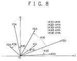
- Fig. 8 is a conception view showing concrete example of control in steps A4, A5, and A8 of Fig. 6.
-
- A preferred embodiment of the present invention will be described in detail in accordance with the accompanying drawings.
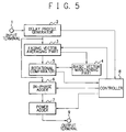
- Fig. 5 is a functional block diagram showing a searcher circuit of the CDMA reception device according to one embodiment of the present invention. The searcher circuit of the CDMA reception device comprises a delay profile generator 2, fading
vector averaging part 3, a basic vector maintaining part 4, arotational comparator 5, an in-phase adder 6, a power adder 7, and acontroller 8. - The delay profile generator 2 inputs therein a digitized complex base band signal from an
input terminal 1. The delay profile generator executes inverse-diffusion to the digitized complex base band signal. The delay profile generator obtains fading vector in every reception timing. The fading vector has required accuracy. The fading vector is obtained with respect to required search range. The delay profile generator 2 generates to be outputted a delay profile of a vector value in every appropriate cycle, for instance, in every symbol cycle. - The fading
vector averaging part 3 selects N maximum values in order of largeness thereof from among the fading vectors obtained by the delay profile generator 2 in accordance with integer number N more than 1 specified by thecontroller 8. The fadingvector averaging part 3 obtains weighted vector mean of respective N fading vectors using weighting factor (scalar value) specified respectively. - The
rotational comparator 5 obtains angle difference " d". A phase of the fading vector which undergoes weighted vector averaging is calculated by the fadingvector averaging part 3. A phase of the basic vector which is maintained in the basic vector maintaining part 4 is compared with the above phase of the fading vector. The angle difference " d" is an angle difference between the phase of the fading vector and the phase of the basic vector. Therotational comparator 5 compares an absolute value of the angle difference " d" with a threshold value " th" which is specified for the sake of thecontroller 8. Therotational comparator 5 notices comparison result thereof to thecontroller 8. When the absolute value of the angle difference " d" is larger than the threshold value " th", therotational comparator 5 replaces the basic vector maintained in the basic vector maintaining part 4 with the fading vector which is subjected to weighted vector averaging in the fadingvector averaging part 3. - The in-
phase adder 6 generates to be maintained a delay profile of vector value which is subjected to the in-phase-addition. The fading vector of the delay profile of the vector value which is generated by the delay profile generator 2 is executed the in-phase-addition in every respective reception timing. - The power adder 7 obtains a power value (square sum of in-phase component and orthogonal component) of the fading vector of the delay profile of the vector value in every reception timing. The in-
phase adder 6 outputs the delay profile of the vector value which undergoes the in-phase-addition. The power value of the fading vector is added to a maintained power value of every reception timing of the delay profile which is subjected to the power-addition. According to this addition of power value, the power adder 7 updates delay profile which is subjected to the power-addition. - The
controller 8 controls respective parts as follows: - The
controller 8 specifies number "N" of the maximum value of the fading vector to be selected to the fadingvector averaging part 3. - The fading
vector averaging part 3 calculates the fading vector which is subjected to the weighted vector averaging. The phase of the basic vector is maintained at the basic vector maintaining part 4. Therotational comparator 5 compares a phase of the fading vector with the phase of the basic vector to calculate an angle difference " d". When an absolute value of the angle difference " d" becomes larger than a threshold value " th", thecontroller 8 outputs the delay profile which is in-phase added, and which is added to be maintained in the in-phase adder 6 to the power adder 7. Further, thecontroller 8 controls in-phase adder 6 so as to replace the delay profile which is in-phase added, and which is added to be maintained in the in-phase adder 6 with a delay profile generated by the delay profile generator 2. - The total number of the delay profile which is generated by the delay profile generator 2 comes to a threshold value "M-th" determined beforehand. The
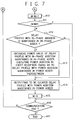
controller 8 outputs the delay profile which is power added, and which is maintained at the power adder 7, to anoutput terminal 9, in every case where the total number of the delay profile which is generated by the delay profile generator 2 comes to a threshold value "M-th" determined beforehand. Subsequently, thecontroller 8 controls the power adder 7 so as to clear it. On this occasion, when the in-phase adder 6 maintains the delay profile which is in-phase added, thecontroller 8 controls the in-phase adder 6 so as to output the delay profile which is in-phase added, and which is added to be maintained, to the power adder 7. Thecontroller 8 executes the power-addition of the delay profile which is in-phase added, which is outputted from the in-phase adder 6, before, thecontroller 8 controls the power adder 7 so as to output the delay profile which is power added. - Figs. 6 and 7 are flowcharts for explaining control flow of the searcher circuit of Fig. 5. Hereinafter, there will be described operation of the searcher circuit of the CDMA reception device according to the present embodiment referring to Figs. 6 and 7.
- The delay profile generator 2 inputs therein digitized complex base band signal inputted from the
input terminal 1. The delay profile generator 2 executes inverse-diffusion of the complex base band signal in the well known signal list according to the means described in the list correlator of the second prior art or according to the appropriate known means. Subsequently, the delay profile generator 2 obtains the fading vector in every reception timing with required accuracy concerning required search range. The delay profile generator 2 generates to be outputted the delay profile of the vector value in every appropriate cycle, for instance, in every symbol cycle (STEP A2). - The
controller 8 controls the fadingvector averaging part 3. The delay profile generator 2 outputs the delay profile of the vector value under the control of thecontroller 8. The fadingvector averaging part 3 selects N maximum values in order of largeness of the fading vectors. The fadingvector averaging part 3 executes weighted-averaging, before calculating the fading vector which is weighted to be averaged (STEP A3). - Next, the
rotational comparator 5 obtains angle difference d between the phase of the fading vector and the phase of basic vector. The fading vector is subjected to weighted-averaging. The basic vector is maintained in the basic vector maintaining part 4. The phase of the fading vector is compared with the phase of the basic vector to obtain the angle difference " d" (STEP A4). Therotational comparator 5 compares an absolute value of the angle difference " d" with the threshold value " th" to be specified for the sake of the controller 8 (STEP A5). - The absolute value of the angle difference " d" is larger than the threshold value " th". In such the case, the
controller 8 controls the in-phase adder 6 so as to update the maintained delay profile which is subjected to the in-phase-addition. The delay profile of the vector value is obtained in STEP A2. The other in-phase added delay profile is maintained in the in-phase adder 6. The delay profile of the vector value is in-phase added to the other in-phase added delay profile in every reception timing. In such the in-phase-addition, thecontroller 8 causes the in-phase adder 6 to be controlled so as to update the maintained delay profile which is subjected to the in-phase-addition (STEP A6). - On the other hand, in STEP A5, the absolute value of the angle difference " d" is already larger than the threshold value " th", on this occasion, phase variation of reception complex base band signal is large, thus it is incapable of improving S / N ratio by the in-phase-addition. Therefore, the
controller 8 obtains a power value of the fading vector in every respective reception timing in terms of the delay profile which is in-phase added until then, and which is maintained in the in-phase adder 6. The delay profile which is subjected to the power-addition is maintained in the power adder 7. The power value of the fading vector is added to the delay profile with the power-addition in every respective reception timing. Thus, thecontroller 8 controls the power adder 7 so as to update the delay profile which is power added according to addition between the power value of the fading vector and the power added delay profile (STEP A7). - Furthermore, the fading vector with weighted-averaging calculated in STEP A3 is taken as a new basic vector, before being stored in the basic vector maintaining part 4 (STEP A8). Simultaneously, the
controller 8 eliminates the in-phase added delay profile which is maintained in the in-phase adder 6. Subsequently, thecontroller 8 causes the delay profile generated in STEP A2 to be maintained newly in the in-phase adder 6. - Fig. 8 is a conception view for explaining one example of control of control flow described-above.
- The delay profile generator 2 generates delay profiles D0, to D5 (not illustrated) in order. FD0 to FD5 shown in Fig. 8 are fading vectors calculated from delay profiles D0 to D5 by the fading vector generator 2. The FD0 to FD5 are fading vector with the weighted-averaging. The fading vector FD0 is stored in the basic vector maintaining part 4 as a basic vector. Subsequently, the fading vectors with the weighted-averaging FD1, FD2, FD3, FD4, and FD5 generated in order. Fig. 8 shows the state of affairs.
- The fading vector with weighted-averaging FD1 is generated together with the basic vector FD0. An absolute value of angle difference " 10" of the fading vector with weighted-averaging FD1 is compared with the threshold value " th" in the
rotational comparator 5. In the result of comparison, since relation between the absolute value of angle difference " 10" of the fading vector with weighted-averaging FD1 and the threshold value " th" is | 10 | < th, the delay profile D1 which is obtained in STEP A2 is in-phase added to the in-phase added delay profile (D0 in this case) which is maintained in the in-phase adder. - An angle difference between the basic vector FD0 and the fading vector with weighted-averaging FD2 and an angle difference between the basic vector FD0 and the fading vector with weighted-averaging FD3 whose respective absolute values are smaller than threshold value " th" are " 20", and " 30" respectively as shown in Fig. 8. Absolute values of " 20", and " 30" are smaller than the threshold value " th". The delay profiles D2, and D3 corresponding to the absolute values of " 20", and " 30" are in-phase added to the in-phase added delay profiles which are maintained in the in-
phase adder 6. - However, an angle difference between the basic vector FD0 and the fading vector with weighted-averaging FD4 whose absolute values is larger than threshold value " th" is " 40". Therefore, the in-phase added delay profile maintained in the in-
phase adder 6 until that time is inputted to the power adder 7. Such the in-phase added delay profile is power added to the power added delay profile which is maintained therein. - The in-phase added delay profile which is maintained in the in-
phase adder 6 is eliminated. A delay profile D4 generated this time is maintained in the in-phase adder 6 newly as an in-phase added delay profile. - Further, the fading vector FD4 with weighted-averaging is stored in the basic vector maintaining part 4 as a new basic vector.
- A delay profile D5 is generated secondly. A fading vector FD5 with weighted-averaging is obtained from the delay profile D5. The fading vector with weighted-averaging FD5 is compared with the basic vector FD4. When an absolute value of an angle difference 54 is smaller than the threshold value th, the delay profile D5 is in-phase added to the delay profile D4 which is maintained in the in-
phase adder 6. - Returning to flowchart of Fig. 6, the in-phase-addition of the delay profile in STEP A6 ends. Replacement of the in-phase added delay profile in STEP A9 ends. On that occasion, both control flows shift to STEP A10 of Fig. 7. The
controller 8 increases an in-phase-addition counter M by 1. Thecontroller 8 compares the in-phase-addition counter M with a threshold value M th determined beforehand (STEP A11). - When the in-phase-addition counter M is smaller than the threshold value M th, the control flow shifts to STEP A16. The
controller 8 judges whether or not communication ends. If the communication ends, thecontroller 8 ends processing (STEP A17). If the communication is in continuity, the control flow returns to STEP A2. Then new delay profile is generated. - In STEP A11, when the in-phase counter M comes to the threshold value M th, a check is implemented whether or not the in-phase added delay profile is maintained in the in-
phase adder 6. Namely a check is implemented whether or not the in-phase added delay profile in STEP A9 is just replaced (STEP A12). - The delay profile with the in-phase-addition is maintained in the in-
phase adder 6. On this occasion, power value of the in-phase added delay profile which is maintained is obtained. The power value of the delay profile is power added to the power added delay profile which is maintained in the power adder 7 until that time in every reception timing (STEP A13). The power added delay profile is outputted to an output terminal 9 (STEP A14). - Furthermore, when the in-phase added delay profile is not maintained in the in-
phase adder 6, the control flow shifts from STEP A12 to STEP A14 directly. The power added delay profile maintained in the power adder 7 until that time is outputted as it is. - In STEP A14, the power added delay profile is outputted, before the in-phase-addition counter M is reset to 0. The control flow shifts from STEP A14 to STEP A16. The
controller 8 judges whether or not the communication ends. When communication ends, thecontroller 8 ends processing (STEP A17). While when the communication is in continuity, the control flow returns to STEP A2. Thus, new delay profile is generated. - As described above, in the reception path-search method of the CDMA receiver according to the present embodiment. On the occasion of generation of the delay profile a method which is different from the conventional method is proposed. In the conventional method, the fading vector is in-phase added during fixed period uniformly. Subsequently, the delay profile which is subjected to vector-addition is obtained. The vector added delay profile is power added to calculate delay profile. In stead of the above conventional method, the proposed reception path-search method is as follows. The angle difference of the fading vector which is subjected to the weighted-averaging is observed. If the angle difference is within the fixed threshold value, the in-phase-addition continues. When the angle difference becomes more than the threshold value, the power-addition is started while switching the in-phase-addition. Therefore, it is capable of controlling number of the in-phase-addition appropriately, in answer to change of the transmission line. It is capable of generating delay profile whose S / N ratio is high, and which delay profile is significant.
- One embodiment of the present invention has been described referring to Figs. 5 to 8. However, the present invention is not restricted by this embodiment. Various kinds of practical applications are conceivable.
- For instance, the
rotational comparator 5 compares the phase of the fading vector which is subjected to weighted vector averaging with the phase of the basic vector maintained in the basic vector maintaining part 4 to obtain the angle difference d therebetween. Only when the absolute value of the angle difference d is larger than the threshold value th, therotational comparator 5 replaces the basic vector with the fading vector which is subjected to weighted vector averaging. The basic vector is maintained in the basic vector maintaining part 4, and the fading vector undergoes weighted vector averaging in the fadingvector averaging part 3. However, there is a case where the absolute value of the angle difference d is smaller than the threshold value th, the in-phase-addition of the delay profile generated in the delay profile generator 2 continues in the in-phase adder 6. It is suitable that the rotational comparator updates the basic vector in such a way that the fading vector which is subjected to weighted vector averaging is vector-added to the basic vector maintained in the basic vector maintaining part 4. - According to this method, it is capable of obtaining more appropriate phase angle of the basic vector while compensating instantaneous variation within the threshold value th of phase of the reception complex base band signal. It is capable of executing switchover of the in-phase-addition and the power-addition of delay profile which reflects state variation of reception path more accurately.
- Furthermore, in the above embodiment, the in-
phase adder 6 outputs the in-phase added delay profile. The power adder 7 obtains power value of the fading vector of the in-phase added delay profile in every reception timing. The power adder 7 obtains the in-phase added delay profile while adding power value of the fading vector in its entirely to the power value in every reception timing of the power added delay profile maintained. - According to this operation, the in-phase added delay profile which is outputted from the in-
phase adder 6 is power-added with weighting of a square of the number of the in-phase-addition. Therefore, it is capable of obtaining the power added delay profile which reflects number of continuity of the in-phase-addition more strongly, namely which reflects stable state of the reception path. However, another weighting addition is also suitable. For instance, the power value of the fading vector in every reception timing of the in-phase added delay profile is divided by number of the in-phase-addition to obtain the value. The value divided is added to the power value in every reception timing of the power added delay profile maintained. - As described-above, according to the present invention, in the searcher circuit of the present invention, it causes the in-phase-addition of the delay profile and the number of the power-addition to be variable. The
rotational comparator 5 obtains the angle difference between the basic vector and the fading vector which is subjected to weighted-averaging. When the absolute value of the angle difference is smaller than the threshold value determined beforehand, angle variation of the phase angle of the reception complex base band signal is small. Therefore, it is judged that it is capable of improving S / N ratio of the delay profile effectively by virtue of the in-phase-addition to continue the in-phase-addition. While, when the absolute value of the angle difference is larger than the threshold value, it is judged that the power-addition is capable of improving S / N ratio rather than the in-phase-addition. The in-phase-addition is switched to the power-addition. - Consequently, according to the present invention, it is capable of switching addition method between the in-phase-addition and the power-addition in answer to the state change of the reception path. The delay profile which reflects the state change of the reception path more accurately, whose S / N ratio is high, and which is significant can be obtained.
- While preferred embodiments of the invention have been described using specific terms, such description is for illustrative purposes only, and it is to be understood that changes and variations may be made without departing from the spirit or scope of the following claims.
Claims (11)
- A reception path search method of a reception device of CDMA (Code Division Multiple Access) communication system comprising the steps of:generating a delay profile in every fixed cycle while plotting fading vector which is obtained in such a way that a reception signal converted into a complex base band signal is subjected to inverse-diffusion using known signal list in every reception timing about fixed range;generating a delay profile which is subjected to the in-phase-addition while continuing vector-addition of the fading vector in every reception timing in connection with continuous delay profile generated in every fixed cycle described above;generating a delay profile which is subjected to the power-addition while continuing the power-addition of fading vector in every reception timing with respect to continuous delay profile which is subjected to the in-phase-addition; andsearching an appropriate reception path while referring to said delay profile which is subjected to the power-addition,
wherein number of continuation of said vector-addition is taken to be variable, said reception path search method monitors a change of phase angle of said complex base band signal which change is reflected to respective delay profiles generated in every said fixed cycle, in the case where such phase angle is changed largely from settled angle of a threshold value, said reception path search method discontinues said continuation of the vector-addition, and then delay profiles which are in-phase added up to that time are taken as an object of the power-addition, before generating delay profile which is subjected to said power-addition. - A reception path search method of a reception device of CDMA (Code Division Multiple Access) communication system comprising the steps of:a delay profile generating step for generating a delay profile in every fixed cycle in such a way that said reception path search method causes fading vector to be plotted in every reception timing in connection with a fixed range, such fading vector is obtained in such a way that reception signal converted into complex base band signal undergoes inverse-diffusion using known signal list;a fading vector averaging step for calculating fading vector which is subjected to a weighted-averaging such that the reception path search method selects maximum value of prescribed number more than one in order of the largeness from among said fading vector plotted in every reception timing in connection with respective these delay profiles, before executing the weighted-averaging;a rotational comparison step for comparing an absolute value of an angle difference between a phase angle of the fading vector which is subjected to the weighted-averaging and a phase angle of a basic vector maintained separately with an angle of a threshold value determined beforehand, before replacing said basic vector by the fading vector which is subjected to the weighted-averaging when the absolute value of said angle difference is larger than said angle of threshold value;an in-phase-addition step for updating a delay profile which is subjected to the in-phase-addition in such away that when the absolute value of said angle difference is judged said angle difference is not larger than said angle of threshold value in such the rotational comparison step, the fading vector of said delay profile providing the fading vector which is subjected to the weighted-averaging is executed a vector-addition in every reception timing to a fading vector of the delay profile which is subjected to the in-phase-addition maintained separately, while when the absolute value of said angle difference is judged said angle difference is larger than said angle of threshold value in such the rotational comparison step, said in-phase-addition step outputs the delay profile which is subjected to the in-phase-addition, as well as said in-phase-addition step updates said delay profile which is subjected to the in-phase-addition while replacing it with said delay profile providing the fading vector which is subjected to the weighted-averaging;a power-addition step for calculating to be maintained delay profile which is subjected to a power-addition in such a way that said power-addition step executes cumulative addition of a power value of fading vector in every reception timing of the delay profile which is subjected to the in-phase-addition which is outputted in said in-phase-addition step;a delay profile outputting step for outputting delay profile which is subjected to the power-addition which is calculated to be maintained in said power-addition step whenever the number of times of generation of delay profile generated in every fixed cycle in said delay profile generating step comes to the number of times determined beforehand; anda reception path selecting step for selecting the most suitable reception timing of one or plural numbers based on the delay profile outputted in said delay profile outputting step, before outputting as a reception path.
- A reception path search method as claimed in claim 2, wherein when said rotational comparison step judges that the absolute value of said angle difference is not larger than said angle of threshold value, said rotational comparison step does not execute updating of said basic vector.
- A reception path search method as claimed in claim 2, wherein when said rotational comparison step judges that the absolute value of said angle difference is not larger than said angle of threshold value, said rotational comparison step updates said basic vector, while executing vector-addition such that said rotational comparison step executes vector-addition between the fading vector which is subjected to the weighted-averaging and said basic vector.
- A reception path search method as claimed in claim 2, wherein in the cases where said delay profile outputting step outputs the delay profile which is subjected to the power-addition, the delay profile which is subjected to the in-phase-addition in said in-phase-addition step is maintained on that occasion, in such the case, said delay profile outputting step executes the power-addition between the delay profile which is subjected to the in-phase-addition and the delay profile which is subjected to the power-addition, before outputting, and said delay profile outputting step clears the maintained delay profile which is subjected to the power-addition.
- A reception path search method as claimed in claim 2, wherein when said power-addition step executes cumulative addition in every reception timing in connection with power value of the fading vector in every reception timing of the delay profile which is subjected to the in-phase-addition in said in-phase-addition step, said power-addition step executes appropriate weighting cumulative addition in consideration of number of the in-phase-addition in said in-phase-addition step of the delay profile which is subjected to the in-phase-addition.
- A searcher circuit of CDMA (Code Division Multiple Access) communication system comprising:a delay profile generator for generating delay profile in every fixed cycle while plotting a fading vector which is obtained in such a way that a reception signal converted into a complex base band signal is subjected to inverse-diffusion using known signal list in every reception timing in relation to fixed range;a fading vector averaging part for calculating a fading vector which is subjected to a weighted-averaging in such a way that said fading vector averaging part selects maximum number of prescribed number more than one in order of the largeness thereof from among said fading vector plotted in every reception timing in connection with respective delay profiles;a basic vector maintaining part for maintaining a basic vector;a rotational comparator for comparing an absolute value of an angle difference between a phase angle of said fading vector which is subjected to the weighted-averaging and a phase angle of said basic vector with an angle of threshold value determined beforehand, and replacing said basic vector with the fading vector which is subjected to the weighted-averaging when said absolute value of said angle difference is larger than said angle of threshold value;an in-phase adder for updating a delay profile which is subjected to the in-phase-addition in such a way that said in-phase adder executes vector-addition between a fading vector of said delay profile generated by said delay profile generator and a fading vector of a maintained delay profile which is subjected to the in-phase-addition in every reception timing, when such control is executed, said in-phase adder outputs said delay profile which is subjected to the in-phase-addition, and said in-phase adder replaces to be updated said delay profile which is subjected to the in-phase-addition by said delay profile generated by said delay profile generator;a power adder for calculating to be maintained a delay profile which is subjected to the power-addition in such a way that said power adder executes cumulative addition of power value of fading vector of every reception timing of the delay profile which is subjected to the in-phase-addition outputted from said in-phase adder in every reception timing;a controller for controlling said in-phase adder so as to output said delay profile which is subjected to the in-phase-addition, and so as to replace to be updated said delay profile which is subjected to the in-phase-addition by said delay profile generated by said delay profile generator when said controller judges that the absolute value of the angle difference between the phase angle of the fading vector which is subjected to the weighted-averaging at said rotational comparator and phase angle of the basic vector is larger than said angle of threshold value, and for controlling said power adder so as to output a delay profile which is subjected to the power-addition which is calculated to be maintained in said power adder whenever the number of times of generation of a delay profile generated in every fixed cycle in said delay profile generator comes to the number of times determined beforehand.
- A searcher circuit of CDMA (Code Division Multiple Access) communication system as claimed in claim 7, wherein said rotational comparator does not update said basic vector when it is judged that the absolute value of the angle difference is not larger than said angle of threshold value.
- A searcher circuit of CDMA (Code Division Multiple Access) communication system as claimed in claim 7, wherein said rotational comparator updates said basic vector while executing vector-addition between said fading vector which is subjected to the weighted-averaging and said basic vector when it is judged that the absolute value of the angle difference is not larger than said angle of threshold value.
- A searcher circuit of CDMA (Code Division Multiple Access) communication system as claimed in claim 7, wherein when said controller causes said power adder to be controlled so as to output said delay profile which is subjected to the power-addition, on this occasion, if said delay profile which is subjected to the in-phase-addition is maintained, said controller executes the power-addition between said delay profile which is subjected to the in-phase-addition and the delay profile which is subjected to the power-addition before outputting it and said controller controls said power adder so as to clear the maintained delay profile which is subjected to the power-addition
- A searcher circuit of CDMA (Code Division Multiple Access) communication system as claimed in claim 7, wherein when said power adder executes appropriate weighting cumulative addition in consideration of the number of times of the in-phase-addition in said in-phase adder of the delay profile which is subjected to the in-phase-addition, said power adder executes cumulative addition of power value of the fading vector of every reception timing of the delay profile which is subjected to the in-phase-addition outputted from said in-phase adder in every reception timing.
Applications Claiming Priority (2)
| Application Number | Priority Date | Filing Date | Title |
|---|---|---|---|
| JP4673299A JP3149868B2 (en) | 1999-02-24 | 1999-02-24 | Receiving path search method and searcher circuit for CDMA receiver |
| JP4673299 | 1999-02-24 |
Publications (3)
| Publication Number | Publication Date |
|---|---|
| EP1032138A2 true EP1032138A2 (en) | 2000-08-30 |
| EP1032138A3 EP1032138A3 (en) | 2003-01-02 |
| EP1032138B1 EP1032138B1 (en) | 2008-11-05 |
Family
ID=12755518
Family Applications (1)
| Application Number | Title | Priority Date | Filing Date |
|---|---|---|---|
| EP20000103400 Expired - Lifetime EP1032138B1 (en) | 1999-02-24 | 2000-02-24 | Reception path search method and searcher circuit of CDMA reception device |
Country Status (7)
| Country | Link |
|---|---|
| US (1) | US6356542B1 (en) |
| EP (1) | EP1032138B1 (en) |
| JP (1) | JP3149868B2 (en) |
| KR (1) | KR100362030B1 (en) |
| CN (1) | CN1192532C (en) |
| BR (1) | BR0000584A (en) |
| DE (1) | DE60040703D1 (en) |
Cited By (1)
| Publication number | Priority date | Publication date | Assignee | Title |
|---|---|---|---|---|
| CN101442771B (en) * | 2007-11-23 | 2011-11-02 | 电信科学技术研究院 | Method and apparatus for implementing PS business status transfer |
Families Citing this family (20)
| Publication number | Priority date | Publication date | Assignee | Title |
|---|---|---|---|---|
| JP3344478B2 (en) * | 1999-07-16 | 2002-11-11 | 日本電気株式会社 | Path search circuit in CDMA cellular system |
| JP3322246B2 (en) * | 1999-07-21 | 2002-09-09 | 日本電気株式会社 | Path search apparatus and method |
| JP3445221B2 (en) * | 2000-05-30 | 2003-09-08 | 松下電器産業株式会社 | Wireless receiving apparatus and wireless receiving method |
| JP3421314B2 (en) * | 2000-10-04 | 2003-06-30 | 松下電器産業株式会社 | Path selection device and path selection method |
| JP3419749B2 (en) * | 2000-10-10 | 2003-06-23 | 松下電器産業株式会社 | Receiving device and receiving method |
| US6680968B2 (en) * | 2001-05-17 | 2004-01-20 | Qualcomm Incorporated | CDMA searcher with time offset compensation |
| JP2002359576A (en) * | 2001-05-31 | 2002-12-13 | Fujitsu Ltd | Cdma-receiving device |
| KR100591700B1 (en) * | 2001-10-06 | 2006-07-03 | 엘지노텔 주식회사 | Method for searching signal path in array antenna system, Apparatus for the same |
| US6748009B2 (en) * | 2002-02-12 | 2004-06-08 | Interdigital Technology Corporation | Receiver for wireless telecommunication stations and method |
| JP4012444B2 (en) * | 2002-08-06 | 2007-11-21 | 松下電器産業株式会社 | Delay profile creation method and delay profile creation apparatus |
| JP4052060B2 (en) | 2002-08-21 | 2008-02-27 | 日本電気株式会社 | CDMA radio apparatus and simple path estimation method used therefor |
| JP4165238B2 (en) * | 2003-01-29 | 2008-10-15 | 日本電気株式会社 | Path search circuit, method and program |
| JP4238987B2 (en) * | 2003-10-08 | 2009-03-18 | 日本電気株式会社 | CDMA receiving method and apparatus |
| CN1332567C (en) * | 2003-11-10 | 2007-08-15 | 华为技术有限公司 | Method for producing power time delay distribution |
| KR100669248B1 (en) * | 2004-10-19 | 2007-01-15 | 한국전자통신연구원 | Initial synchronization acquisition appatatus and method for parallel processed DS-CDMA UWB system and receiver using as the same |
| CN1707989B (en) * | 2005-05-13 | 2010-12-22 | 上海宣普实业有限公司 | Method for timing tracking path search in CDMA system |
| KR101182857B1 (en) * | 2008-12-08 | 2012-09-14 | 한국전자통신연구원 | Synchronization tracking apparatus and method thereof |
| JP5423505B2 (en) * | 2010-03-17 | 2014-02-19 | 富士通株式会社 | Wireless base station and communication method |
| US8849188B2 (en) * | 2012-08-02 | 2014-09-30 | Intel Corporation | Detecting sub-meter region of interest using radio signals |
| KR102158035B1 (en) * | 2018-05-24 | 2020-09-22 | 주식회사 탑 엔지니어링 | Apparatus for cutting substrate |
Citations (1)
| Publication number | Priority date | Publication date | Assignee | Title |
|---|---|---|---|---|
| JPH09181704A (en) * | 1995-12-22 | 1997-07-11 | N T T Ido Tsushinmo Kk | Cdma multi-path searth method and cdma signal receiver |
Family Cites Families (1)
| Publication number | Priority date | Publication date | Assignee | Title |
|---|---|---|---|---|
| US5937014A (en) * | 1997-03-27 | 1999-08-10 | Telefonaktiebolaget Lm Ericsson | Self-synchronizing equalization techniques and systems |
-
1999
- 1999-02-24 JP JP4673299A patent/JP3149868B2/en not_active Expired - Fee Related
-
2000
- 2000-02-23 US US09/511,303 patent/US6356542B1/en not_active Expired - Fee Related
- 2000-02-24 CN CNB001030914A patent/CN1192532C/en not_active Expired - Fee Related
- 2000-02-24 KR KR1020000009156A patent/KR100362030B1/en not_active IP Right Cessation
- 2000-02-24 EP EP20000103400 patent/EP1032138B1/en not_active Expired - Lifetime
- 2000-02-24 DE DE60040703T patent/DE60040703D1/en not_active Expired - Fee Related
- 2000-02-24 BR BR0000584A patent/BR0000584A/en not_active IP Right Cessation
Patent Citations (1)
| Publication number | Priority date | Publication date | Assignee | Title |
|---|---|---|---|---|
| JPH09181704A (en) * | 1995-12-22 | 1997-07-11 | N T T Ido Tsushinmo Kk | Cdma multi-path searth method and cdma signal receiver |
Non-Patent Citations (2)
| Title |
|---|
| HAMADA H ET AL: "Performance evaluation of the path search process for the W-CDMA system" , VEHICULAR TECHNOLOGY CONFERENCE, 1999 IEEE 49TH HOUSTON, TX, USA 16-20 MAY 1999, PISCATAWAY, NJ, USA,IEEE, US, PAGE(S) 980-984 XP010342058 ISBN: 0-7803-5565-2 * paragraph [0003]; figure 3 * * |
| PATENT ABSTRACTS OF JAPAN vol. 1997, no. 11, 28 November 1997 (1997-11-28) & JP 09 181704 A (N T T IDO TSUSHINMO KK), 11 July 1997 (1997-07-11) * |
Cited By (1)
| Publication number | Priority date | Publication date | Assignee | Title |
|---|---|---|---|---|
| CN101442771B (en) * | 2007-11-23 | 2011-11-02 | 电信科学技术研究院 | Method and apparatus for implementing PS business status transfer |
Also Published As
| Publication number | Publication date |
|---|---|
| CN1192532C (en) | 2005-03-09 |
| EP1032138A3 (en) | 2003-01-02 |
| BR0000584A (en) | 2000-12-26 |
| US6356542B1 (en) | 2002-03-12 |
| EP1032138B1 (en) | 2008-11-05 |
| JP2000244366A (en) | 2000-09-08 |
| DE60040703D1 (en) | 2008-12-18 |
| JP3149868B2 (en) | 2001-03-26 |
| KR100362030B1 (en) | 2002-11-22 |
| CN1264970A (en) | 2000-08-30 |
| KR20000076725A (en) | 2000-12-26 |
Similar Documents
| Publication | Publication Date | Title |
|---|---|---|
| EP1032138B1 (en) | Reception path search method and searcher circuit of CDMA reception device | |
| KR100275613B1 (en) | Cdma receiving apparatus | |
| US6201828B1 (en) | Fine estimation of multipath delays in spread-spectrum signals | |
| EP1134907B1 (en) | Method and apparatus for decoding a spread spectrum signal for CDMA | |
| JP2991196B1 (en) | CDMA receiving method and receiver | |
| US7042862B1 (en) | Path searching method and device | |
| EP1499032A1 (en) | Sir measurement device and method | |
| JP2000049662A (en) | Demodulating circuit of cdma receiving device | |
| EP1280282A2 (en) | Apparatus and method for measuring SIR in a Rake-receiver | |
| US7110436B2 (en) | CDMA receiving apparatus with transmission power control using previous SIR value | |
| JP2973416B1 (en) | RAKE receiving circuit | |
| KR20020026270A (en) | Channel presuming system and channel presuming method | |
| JP3418981B2 (en) | Spread spectrum communication synchronization acquisition circuit | |
| JP4022810B2 (en) | Array antenna wireless communication device and receiving device | |
| US20040106421A1 (en) | Communication device | |
| US7593381B2 (en) | Mobile communication terminal, and antenna array directivity-pattern-controlling method | |
| US20040017844A1 (en) | Channel estimation in spread spectrum system | |
| KR100445496B1 (en) | Receiving device and receiving method | |
| JP2000091973A (en) | Rake synthesis circuit | |
| US6775341B2 (en) | Time recovery circuit and method for synchronizing timing of a signal in a receiver to timing of the signal in a transmitter | |
| JP2001196974A (en) | Cdma wireless receiver and control method | |
| KR100666985B1 (en) | Method and apparatus for calibrating in adaptive array antenna system | |
| EP1392031B1 (en) | Fading frequency estimation apparatus | |
| JP2003209485A (en) | Control method for radio communication device and radio communication device | |
| JP2002261852A (en) | Synchronization detecting circuit |
Legal Events
| Date | Code | Title | Description |
|---|---|---|---|
| PUAI | Public reference made under article 153(3) epc to a published international application that has entered the european phase |
Free format text: ORIGINAL CODE: 0009012 |
|
| AK | Designated contracting states |
Kind code of ref document: A2 Designated state(s): AT BE CH CY DE DK ES FI FR GB GR IE IT LI LU MC NL PT SE |
|
| AX | Request for extension of the european patent |
Free format text: AL;LT;LV;MK;RO;SI |
|
| PUAL | Search report despatched |
Free format text: ORIGINAL CODE: 0009013 |
|
| AK | Designated contracting states |
Kind code of ref document: A3 Designated state(s): AT BE CH CY DE DK ES FI FR GB GR IE IT LI LU MC NL PT SE |
|
| AX | Request for extension of the european patent |
Free format text: AL;LT;LV;MK;RO;SI |
|
| 17P | Request for examination filed |
Effective date: 20021116 |
|
| AKX | Designation fees paid |
Designated state(s): DE GB |
|
| 17Q | First examination report despatched |
Effective date: 20010208 |
|
| 17Q | First examination report despatched |
Effective date: 20010208 |
|
| GRAP | Despatch of communication of intention to grant a patent |
Free format text: ORIGINAL CODE: EPIDOSNIGR1 |
|
| GRAS | Grant fee paid |
Free format text: ORIGINAL CODE: EPIDOSNIGR3 |
|
| GRAA | (expected) grant |
Free format text: ORIGINAL CODE: 0009210 |
|
| AK | Designated contracting states |
Kind code of ref document: B1 Designated state(s): DE GB |
|
| REG | Reference to a national code |
Ref country code: GB Ref legal event code: FG4D |
|
| REF | Corresponds to: |
Ref document number: 60040703 Country of ref document: DE Date of ref document: 20081218 Kind code of ref document: P |
|
| PGFP | Annual fee paid to national office [announced via postgrant information from national office to epo] |
Ref country code: DE Payment date: 20090127 Year of fee payment: 10 |
|
| PGFP | Annual fee paid to national office [announced via postgrant information from national office to epo] |
Ref country code: GB Payment date: 20090326 Year of fee payment: 10 |
|
| PLBE | No opposition filed within time limit |
Free format text: ORIGINAL CODE: 0009261 |
|
| STAA | Information on the status of an ep patent application or granted ep patent |
Free format text: STATUS: NO OPPOSITION FILED WITHIN TIME LIMIT |
|
| 26N | No opposition filed |
Effective date: 20090806 |
|
| GBPC | Gb: european patent ceased through non-payment of renewal fee |
Effective date: 20100224 |
|
| PG25 | Lapsed in a contracting state [announced via postgrant information from national office to epo] |
Ref country code: DE Free format text: LAPSE BECAUSE OF NON-PAYMENT OF DUE FEES Effective date: 20100901 |
|
| PG25 | Lapsed in a contracting state [announced via postgrant information from national office to epo] |
Ref country code: GB Free format text: LAPSE BECAUSE OF NON-PAYMENT OF DUE FEES Effective date: 20100224 |