EP1031510B1 - Turbo fan engine nacelle exhaust system with concave primary nozzle plug - Google Patents
Turbo fan engine nacelle exhaust system with concave primary nozzle plug Download PDFInfo
- Publication number
- EP1031510B1 EP1031510B1 EP00200285A EP00200285A EP1031510B1 EP 1031510 B1 EP1031510 B1 EP 1031510B1 EP 00200285 A EP00200285 A EP 00200285A EP 00200285 A EP00200285 A EP 00200285A EP 1031510 B1 EP1031510 B1 EP 1031510B1
- Authority
- EP
- European Patent Office
- Prior art keywords
- primary
- exhaust system
- nozzle
- turbo fan
- primary nozzle
- Prior art date
- Legal status (The legal status is an assumption and is not a legal conclusion. Google has not performed a legal analysis and makes no representation as to the accuracy of the status listed.)
- Expired - Lifetime
Links
- 230000035939 shock Effects 0.000 claims description 17
- 230000001419 dependent effect Effects 0.000 claims description 3
- 230000006835 compression Effects 0.000 description 9
- 238000007906 compression Methods 0.000 description 9
- 238000009413 insulation Methods 0.000 description 3
- 230000015572 biosynthetic process Effects 0.000 description 1
- 230000002349 favourable effect Effects 0.000 description 1
- 239000000446 fuel Substances 0.000 description 1
- 230000003993 interaction Effects 0.000 description 1
- 238000012986 modification Methods 0.000 description 1
- 230000004048 modification Effects 0.000 description 1
- 230000001629 suppression Effects 0.000 description 1
Images


Classifications
-
- F—MECHANICAL ENGINEERING; LIGHTING; HEATING; WEAPONS; BLASTING
- F02—COMBUSTION ENGINES; HOT-GAS OR COMBUSTION-PRODUCT ENGINE PLANTS
- F02K—JET-PROPULSION PLANTS
- F02K1/00—Plants characterised by the form or arrangement of the jet pipe or nozzle; Jet pipes or nozzles peculiar thereto
- F02K1/78—Other construction of jet pipes
-
- B—PERFORMING OPERATIONS; TRANSPORTING
- B64—AIRCRAFT; AVIATION; COSMONAUTICS
- B64D—EQUIPMENT FOR FITTING IN OR TO AIRCRAFT; FLIGHT SUITS; PARACHUTES; ARRANGEMENT OR MOUNTING OF POWER PLANTS OR PROPULSION TRANSMISSIONS IN AIRCRAFT
- B64D33/00—Arrangement in aircraft of power plant parts or auxiliaries not otherwise provided for
- B64D33/04—Arrangement in aircraft of power plant parts or auxiliaries not otherwise provided for of exhaust outlets or jet pipes
- B64D33/06—Silencing exhaust or propulsion jets
-
- F—MECHANICAL ENGINEERING; LIGHTING; HEATING; WEAPONS; BLASTING
- F02—COMBUSTION ENGINES; HOT-GAS OR COMBUSTION-PRODUCT ENGINE PLANTS
- F02K—JET-PROPULSION PLANTS
- F02K1/00—Plants characterised by the form or arrangement of the jet pipe or nozzle; Jet pipes or nozzles peculiar thereto
-
- F—MECHANICAL ENGINEERING; LIGHTING; HEATING; WEAPONS; BLASTING
- F02—COMBUSTION ENGINES; HOT-GAS OR COMBUSTION-PRODUCT ENGINE PLANTS
- F02K—JET-PROPULSION PLANTS
- F02K1/00—Plants characterised by the form or arrangement of the jet pipe or nozzle; Jet pipes or nozzles peculiar thereto
- F02K1/38—Introducing air inside the jet
- F02K1/386—Introducing air inside the jet mixing devices in the jet pipe, e.g. for mixing primary and secondary flow
-
- F—MECHANICAL ENGINEERING; LIGHTING; HEATING; WEAPONS; BLASTING
- F05—INDEXING SCHEMES RELATING TO ENGINES OR PUMPS IN VARIOUS SUBCLASSES OF CLASSES F01-F04
- F05D—INDEXING SCHEME FOR ASPECTS RELATING TO NON-POSITIVE-DISPLACEMENT MACHINES OR ENGINES, GAS-TURBINES OR JET-PROPULSION PLANTS
- F05D2250/00—Geometry
- F05D2250/70—Shape
- F05D2250/71—Shape curved
- F05D2250/712—Shape curved concave
-
- Y—GENERAL TAGGING OF NEW TECHNOLOGICAL DEVELOPMENTS; GENERAL TAGGING OF CROSS-SECTIONAL TECHNOLOGIES SPANNING OVER SEVERAL SECTIONS OF THE IPC; TECHNICAL SUBJECTS COVERED BY FORMER USPC CROSS-REFERENCE ART COLLECTIONS [XRACs] AND DIGESTS
- Y02—TECHNOLOGIES OR APPLICATIONS FOR MITIGATION OR ADAPTATION AGAINST CLIMATE CHANGE
- Y02T—CLIMATE CHANGE MITIGATION TECHNOLOGIES RELATED TO TRANSPORTATION
- Y02T50/00—Aeronautics or air transport
- Y02T50/60—Efficient propulsion technologies, e.g. for aircraft
Definitions
- the present invention relates to a turbo fan engine nacelle exhaust system as defined in the preamble of claim 1.
- Such an exhaust system is generally known, e.g. from US-A-3,897,001.
- FIG. 1 a prior art turbo fan engine nacelle 10 of the general type as disclosed in US-A3,897,001 is shown.
- the prior art turbo fan engine nacelle 10 is shown attached to a wing 12 of an aircraft.
- the turbo fan engine nacelle 10 houses an engine 11 including a fan 14 which draws air through inlet 15, and forces the air to be exhausted through a primary nozzle 16 and fan nozzle 18.
- the primary nozzle 16 is bordered interiorly by the primary nozzle plug 20, and bordered exteriorly by the primary nozzle sleeve 23.
- the fan nozzle 18 is bordered interiorly by a core cowl 22, and bordered exteriorly by a fan nozzle sleeve 24.
- the engine 11 forces exhaust through the primary nozzle 16 and fan nozzle 18, and as shown in Figure 1, the imperfectly expanding supersonic flow 26 exhausted from the turbo fan engine 11 interacts with turbulent air structures from the jet and creates a dominant "shock cell” noise producing region 28 which radiates sound waves 29 to the cabin, thereby producing undesirable aircraft cabin noise.
- the shock cell structure in the exhaust plume of an engine is the result of two flow features: (1) a compression of the secondary (fan) flow 30 on the aft section of core cowl 22 and the resulting expansion off the secondary-ambient flow shear layer 34; and (2) compression waves necessary to turn the radially contracting secondary flow 30 and primary flow 32 in the axial direction.
- the compression wave near the core cowl trailing edge reflects alternately off the secondary and ambient flow shear layer 34 as an expansion wave and the primary-secondary shear layer 36 as a compression wave.
- This initial wave reflection pattern is reinforced in the flow turning region 38 above and immediately aft of the primary nozzle plug 20, thereby resulting in higher (shock cell) strength for the compression and expansion waves between the shear layers 34,36.
- turbo fan engine nacelle exhaust system which produces lower shock cell noise to the cabin without requiring additional sound insulation in the aircraft.
- US-A-2,928,235 discloses an exhaust system for a turbo jet engine mounted in an aircraft wing, which is particularly suited for supersonic flight.
- This prior art exhaust system includes an nozzle plug and a circular annular wall arranged between the nozzle plug and a cylindrical engine casing and separating the turbo jet exhaust into a primary flow and a secondary flow.
- the nozzle plug has a concave outer surface. This exhaust system is said to reduce aircraft drag at supersonic speed.
- the prior art document is not at all concerned with noise suppression for supersonic aircraft.
- the present invention reduces shock cell noise produced by a turbo fan engine nacelle exhaust system by reducing shock strength of the engine exhaust.
- This is achieved in an exhaust system having the features of the preamble of claim 1 in that the outer surface of the primary nozzle plug is concave when viewed in side elevation, the concave outer surface having a radius of curvature (R c ) ; and in that the primary nozzle plug and core cowl define a ratio R c / ⁇ H between approximately 14 and 18, thereby reducing shock-associated noise of a turbo fan engine housed within the nacelle.
- turbo fan engine nacelle exhaust system a schematic profile view of a turbo fan engine nacelle exhaust system is shown in accordance with the present invention.
- the turbo fan engine nacelle exhaust system is in most other respects similar to the prior art turbo fan engine nacelle exhaust system described above with reference to Figures 1-3, except the outer surface 50 of the primary nozzle plug 20' is concave when viewed in side elevation as shown in Figures 4 and 5, and the exit of primary nozzle 16' is specially placed relative to the exit of fan nozzle 18'.
- the contoured or concave outer surface 50 of the primary nozzle plug 20' is designed to reduce the strength of the shock cell structure of the engine exhaust flow.
- a rapid expansion of the primary flow 32' immediately downstream of the exit of primary nozzle exit 16' is used to minimize the expansion wave reflection (as a compression wave) of the initial core cowl shock. This expansion occurs in the low pressure area 39'.
- the extended concave region of the outer surface 50 of the primary nozzle plug 20' provides a wide high pressure region 41' in the primary flow 32' which produces a smooth turning of the secondary flow 30' with reduced or minimized compression wave formation. Accordingly, the flow turning region 38' has weak waves therein as a result of cancellation between expansion and compression waves which bounce between the shear layers 34',36'.
- Figure 6 schematically illustrates flow pressure along the plume centerline (corresponding with the central axis 19 shown in Figure 2) versus the discharge distance, comparing a prior art design (A) to the turbo fan engine nacelle design of the present invention (B). As shown, with the present invention (B), amplitude of the pressure expansion and compression waves is substantially reduced in comparison to the amplitude of the pressure waves in a prior art turbo fan engine nacelle (A).
- the vertical axis of Figure 6 is pressure P along the plume centerline, and the horizontal axis is discharge distance d.
- the present invention is particularly characterized by the specific dimensioning of the radius of curvature R c of the outer surface 50 of the primary nozzle plug 20', and also by specific placement of the primary nozzle exit 16' relative to the exit of fan nozzle exit 18'.
- the primary nozzle 16' is bordered interiorly by the primary nozzle plug 20' and bordered exteriorly by the primary nozzle sleeve 23'.
- the fan nozzle 18' is bordered interiorly by the core cowl 22' and bordered exteriorly by the fan nozzle sleeve 24'.
- the primary nozzle plug 20' includes the generally cone shaped outer surface 50 which is concave when viewed in side elevation to form the radius of curvature R c , referenced above.
- the core cowl 22' has a distal end 54 which is radially spaced from the outer surface 50 of the primary nozzle plug 20' by a distance ⁇ H in a direction perpendicular to the central axis 19'.
- the primary nozzle plug 20' and core cowl 22' define a ratio R c / ⁇ H between approximately 14 and 18, thereby reducing shock associated noise of the turbo fan engine.
- the distal end 54 of the core cowl 22' has a core cowl radius R p with respect to the central axis 19'.
- a discharge end 56 of the fan nozzle sleeve 24' has a fan nozzle sleeve radius Rf, wherein the ratio R p /R f is between approximately 0.4 and 0.6 to optimally size the primary nozzle 16' and fan nozzle 18'.
- the primary plug angle ⁇ p at the primary nozzle exit is preferably between 13° and 19°.
- R p 72.6 cm (28.6 inches)
- ⁇ H 23.9 cm (9.4 inches)
- R c 381 cm (150 inches)
Landscapes
- Engineering & Computer Science (AREA)
- Chemical & Material Sciences (AREA)
- Combustion & Propulsion (AREA)
- Mechanical Engineering (AREA)
- General Engineering & Computer Science (AREA)
- Aviation & Aerospace Engineering (AREA)
- Structures Of Non-Positive Displacement Pumps (AREA)
- Jet Pumps And Other Pumps (AREA)
- Exhaust Silencers (AREA)
Description
- The present invention relates to a turbo fan engine nacelle exhaust system as defined in the preamble of claim 1. Such an exhaust system is generally known, e.g. from US-A-3,897,001.
- Referring to Figures 1, 2 and 3, a prior art turbo
fan engine nacelle 10 of the general type as disclosed in US-A3,897,001 is shown. In Figure 1, the prior art turbofan engine nacelle 10 is shown attached to awing 12 of an aircraft. As shown in Figure 2, the turbofan engine nacelle 10 houses an engine 11 including afan 14 which draws air throughinlet 15, and forces the air to be exhausted through aprimary nozzle 16 andfan nozzle 18. Theprimary nozzle 16 is bordered interiorly by theprimary nozzle plug 20, and bordered exteriorly by theprimary nozzle sleeve 23. Thefan nozzle 18 is bordered interiorly by acore cowl 22, and bordered exteriorly by afan nozzle sleeve 24. Accordingly, the engine 11 forces exhaust through theprimary nozzle 16 andfan nozzle 18, and as shown in Figure 1, the imperfectly expandingsupersonic flow 26 exhausted from the turbo fan engine 11 interacts with turbulent air structures from the jet and creates a dominant "shock cell"noise producing region 28 which radiatessound waves 29 to the cabin, thereby producing undesirable aircraft cabin noise. - Referring to Figure 3, the shock cell structure in the exhaust plume of an engine is the result of two flow features: (1) a compression of the secondary (fan)
flow 30 on the aft section ofcore cowl 22 and the resulting expansion off the secondary-ambientflow shear layer 34; and (2) compression waves necessary to turn the radially contractingsecondary flow 30 andprimary flow 32 in the axial direction. The compression wave near the core cowl trailing edge reflects alternately off the secondary and ambientflow shear layer 34 as an expansion wave and the primary-secondary shear layer 36 as a compression wave. This initial wave reflection pattern is reinforced in theflow turning region 38 above and immediately aft of theprimary nozzle plug 20, thereby resulting in higher (shock cell) strength for the compression and expansion waves between theshear layers - The common solution to the cabin noise problem is to add insulation to the aircraft. However, additional insulation adds significant weight which reduces fuel economy of the aircraft and also reduces passenger carrying capacity of the aircraft.
- Accordingly, it is desirable to provide a turbo fan engine nacelle exhaust system which produces lower shock cell noise to the cabin without requiring additional sound insulation in the aircraft.
- US-A-2,928,235 discloses an exhaust system for a turbo jet engine mounted in an aircraft wing, which is particularly suited for supersonic flight. This prior art exhaust system includes an nozzle plug and a circular annular wall arranged between the nozzle plug and a cylindrical engine casing and separating the turbo jet exhaust into a primary flow and a secondary flow. The nozzle plug has a concave outer surface. This exhaust system is said to reduce aircraft drag at supersonic speed. The prior art document is not at all concerned with noise suppression for supersonic aircraft.
- The present invention reduces shock cell noise produced by a turbo fan engine nacelle exhaust system by reducing shock strength of the engine exhaust. This is achieved in an exhaust system having the features of the preamble of claim 1 in that the outer surface of the primary nozzle plug is concave when viewed in side elevation, the concave outer surface having a radius of curvature (Rc) ; and in that the primary nozzle plug and core cowl define a ratio Rc/ΔH between approximately 14 and 18, thereby reducing shock-associated noise of a turbo fan engine housed within the nacelle. By providing the primary nozzle plug with a concave conical shape and by optimally designing the primary nozzle and fan nozzle aerodynamic lines, shock strength of the engine exhaust and consequently shock cell noise to the cabin is effectively reduced.
- Preferred embodiments of the inventive turbo fan engine nacelle exhaust system form the subject matter of the dependent claims.
- FIGURE 1 shows a schematic side view of a prior art turbo fan engine nacelle exhaust system attached to the wing of an aircraft, illustrating a dominant shock cell noise producing region behind the engine;
- FIGURE 2 shows a cross-sectional side elevation view of the prior art turbo fan engine nacelle exhaust system of Figure 1;
- FIGURE 3 shows a schematic illustration of exhaust flow from a prior art turbo fan engine nacelle exhaust system;
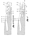
- FIGURE 4 shows a schematic partial profile of a turbo fan engine nacelle exhaust system in accordance with the present invention illustrating exhaust flow therefrom;
- FIGURE 5 shows a schematic partial profile of a turbo fan engine nacelle exhaust system in accordance with the present invention; and
- FIGURE 6 shows a graphical illustration of flow pressure along the plume centerline vs. distance, comparing a prior art turbo fan engine nacelle exhaust system to the turbo fan engine nacelle exhaust system of the present invention.
- Referring to Figures 4 and 5, a schematic profile view of a turbo fan engine nacelle exhaust system is shown in accordance with the present invention. The turbo fan engine nacelle exhaust system is in most other respects similar to the prior art turbo fan engine nacelle exhaust system described above with reference to Figures 1-3, except the
outer surface 50 of the primary nozzle plug 20' is concave when viewed in side elevation as shown in Figures 4 and 5, and the exit of primary nozzle 16' is specially placed relative to the exit of fan nozzle 18'. - The contoured or concave
outer surface 50 of the primary nozzle plug 20' is designed to reduce the strength of the shock cell structure of the engine exhaust flow. First, a rapid expansion of the primary flow 32' immediately downstream of the exit of primary nozzle exit 16' is used to minimize the expansion wave reflection (as a compression wave) of the initial core cowl shock. This expansion occurs in the low pressure area 39'. Second, the extended concave region of theouter surface 50 of the primary nozzle plug 20' provides a wide high pressure region 41' in the primary flow 32' which produces a smooth turning of the secondary flow 30' with reduced or minimized compression wave formation. Accordingly, the flow turning region 38' has weak waves therein as a result of cancellation between expansion and compression waves which bounce between the shear layers 34',36'. - These favorable flow interactions induced by the concave
outer surface 50 of the primary nozzle plug 20' minimize the strength of the shock cell system from 2 to 5 fan nozzle diameters (2 Rf) downstream of the primary nozzle 16'. This reduction of the shock cell strength reduces the shock associated noise of the engine exhaust. Figure 6 schematically illustrates flow pressure along the plume centerline (corresponding with thecentral axis 19 shown in Figure 2) versus the discharge distance, comparing a prior art design (A) to the turbo fan engine nacelle design of the present invention (B). As shown, with the present invention (B), amplitude of the pressure expansion and compression waves is substantially reduced in comparison to the amplitude of the pressure waves in a prior art turbo fan engine nacelle (A). The vertical axis of Figure 6 is pressure P along the plume centerline, and the horizontal axis is discharge distance d. - Returning to Figure 5, the present invention is particularly characterized by the specific dimensioning of the radius of curvature Rc of the
outer surface 50 of the primary nozzle plug 20', and also by specific placement of the primary nozzle exit 16' relative to the exit of fan nozzle exit 18'. As shown, the primary nozzle 16' is bordered interiorly by the primary nozzle plug 20' and bordered exteriorly by the primary nozzle sleeve 23'. The fan nozzle 18' is bordered interiorly by the core cowl 22' and bordered exteriorly by the fan nozzle sleeve 24'. - The primary nozzle plug 20' includes the generally cone shaped
outer surface 50 which is concave when viewed in side elevation to form the radius of curvature Rc, referenced above. The core cowl 22' has adistal end 54 which is radially spaced from theouter surface 50 of the primary nozzle plug 20' by a distance ΔH in a direction perpendicular to the central axis 19'. - Preferably, the primary nozzle plug 20' and core cowl 22' define a ratio Rc/ΔH between approximately 14 and 18, thereby reducing shock associated noise of the turbo fan engine.
- The
distal end 54 of the core cowl 22' has a core cowl radius Rp with respect to the central axis 19'. Adischarge end 56 of the fan nozzle sleeve 24' has a fan nozzle sleeve radius Rf, wherein the ratio Rp/Rf is between approximately 0.4 and 0.6 to optimally size the primary nozzle 16' and fan nozzle 18'. - Additionally, referring to Figure 5, the primary plug angle φp at the primary nozzle exit is preferably between 13° and 19°.
- By way of example, in a preferred turbo fan engine nacelle design, Rp = 39.1 cm (15.4 inches), ΔH = 16.5 cm (6.5 inches), Rc = 279 cm (110 inches), φp = 17° and the axial distance between the
distal end 54 of the core cowl 22' and the distal end of the primary nozzle plug is 96.5 cm (38 inches). And in another preferred turbo fan engine nacelle design, Rp = 72.6 cm (28.6 inches), ΔH = 23.9 cm (9.4 inches), Rc = 381 cm (150 inches), φp = 15° and the axial distance between thedistal end 54 of the core cowl 24' and the distal end of the primary nozzle plug 20' is 221 cm (87 inches). - While an embodiment of the invention has been illustrated and described, it is not intended that such disclosure illustrate and describe all possible forms of the invention. It is intended that the following claims cover all modifications and alternative designs, and all equivalents.
Claims (5)
- A turbo fan engine nacelle exhaust system comprising:a primary nozzle (16') and a fan nozzle (18') positioned along a common central axis (19'), the primary nozzle (16') being bordered interiorly by a primary nozzle plug (20') and bordered exteriorly by a primary nozzle sleeve(24'), and the fan nozzle being bordered interiorly by a core cowl (22') and bordered exteriorly by a fan nozzle sleeve (24');wherein the primary nozzle plug (20') includes a generally cone-shaped outer surface (50'); and
wherein the core cowl (22') has a distal end (54) which is radially spaced from the outer surface (50) of the primary plug (20') by a distance (ΔH) in a direction perpendicular to the central axis (19');
characterized in that:the outer surface (50) of the primary nozzle plug (20') is concave when viewed in side elevation, the concave outer surface (50) having a radius of curvature (Rc);and in that the primary nozzle plug (20') and core cowl (22') define a ratio Rc/ΔH between approximately 14 and 18, thereby reducing shock-associated noise of a turbo fan engine housed within the nacelle. - The turbo fan engine nacelle exhaust system of claim 1, characterized in that the distal end (54) of the core cowl (22') has a core cowl radius Rp with respect to the central axis (19'), and a discharge end (56) of the fan nozzle sleeve (24') has a fan nozzle sleeve radius Rf,
wherein a ratio Rp/Rf is between approximately 0.4 and 0.6. - The turbo fan engine nacelle exhaust system of claim 1 or 2, characterized in that the outer surface (30) of the primary plug (20') forms a primary plug angle φp between approximately 1° and 19° with respect to the central axis (19') at the primary nozzle exit.
- The turbo fan engine nacelle exhaust system of claims 2 or 3 when dependent on claim 2, characterized in that said radius of curvature (Rc) is constant.
- The turbo fan engine nacelle exhaust system of claims 2 or 3 when dependent on claim 2, characterized in that said radius of curvature (Rc) is variable.
Applications Claiming Priority (2)
| Application Number | Priority Date | Filing Date | Title |
|---|---|---|---|
| US257408 | 1999-02-25 | ||
| US09/257,408 US6178740B1 (en) | 1999-02-25 | 1999-02-25 | Turbo fan engine nacelle exhaust system with concave primary nozzle plug |
Publications (3)
| Publication Number | Publication Date |
|---|---|
| EP1031510A2 EP1031510A2 (en) | 2000-08-30 |
| EP1031510A3 EP1031510A3 (en) | 2002-03-27 |
| EP1031510B1 true EP1031510B1 (en) | 2006-11-22 |
Family
ID=22976203
Family Applications (1)
| Application Number | Title | Priority Date | Filing Date |
|---|---|---|---|
| EP00200285A Expired - Lifetime EP1031510B1 (en) | 1999-02-25 | 2000-01-27 | Turbo fan engine nacelle exhaust system with concave primary nozzle plug |
Country Status (4)
| Country | Link |
|---|---|
| US (1) | US6178740B1 (en) |
| EP (1) | EP1031510B1 (en) |
| CA (1) | CA2296833C (en) |
| DE (1) | DE60031902T2 (en) |
Families Citing this family (18)
| Publication number | Priority date | Publication date | Assignee | Title |
|---|---|---|---|---|
| US7032387B2 (en) * | 2004-01-20 | 2006-04-25 | Pratt & Whitney Canada Corp. | Axisymmetric flap on gas turbine exhaust centerbody |
| US7805925B2 (en) | 2006-08-18 | 2010-10-05 | Pratt & Whitney Canada Corp. | Gas turbine engine exhaust duct ventilation |
| FR2921977B1 (en) * | 2007-10-08 | 2012-09-21 | Airbus France | DOUBLE FLOW TURBOMOTEUR FOR AIRCRAFT |
| FR2972224B1 (en) | 2011-03-04 | 2018-04-20 | Safran Aircraft Engines | TUYERE WITH DOWN CORE HAVING A HEAVY CURVATURE |
| US9353704B2 (en) * | 2011-08-19 | 2016-05-31 | Gulfstream Aerospace Corporation | Air inlet arrangement and method of making the same |
| US9261047B2 (en) * | 2012-05-29 | 2016-02-16 | Lockheed Martin Corporation | Jet exhaust noise reduction |
| US20140083079A1 (en) * | 2012-09-26 | 2014-03-27 | United Technologies Corporation | Geared turbofan primary and secondary nozzle integration geometry |
| US9009966B2 (en) | 2013-03-15 | 2015-04-21 | Northrop Gurmman Systems Corporation | Internal/external single expansion ramp nozzle with integrated third stream |
| US10094332B2 (en) | 2014-09-03 | 2018-10-09 | The Boeing Company | Core cowl for a turbofan engine |
| US10618638B2 (en) * | 2015-09-22 | 2020-04-14 | Nctar, Llc | Shockwave mitigation system for supersonic aircraft |
| PL414889A1 (en) * | 2015-11-23 | 2017-06-05 | General Electric Company | Jet engine outlet compression cowling |
| PL420340A1 (en) * | 2017-01-30 | 2018-08-13 | General Electric Company | Reducing of the outlet nozzle shock wave |
| US11125157B2 (en) | 2017-09-22 | 2021-09-21 | The Boeing Company | Advanced inlet design |
| CN110594044B (en) * | 2019-10-17 | 2022-03-18 | 哈尔滨工程大学 | A flexible extension nozzle with adaptive height |
| CN112455699B (en) * | 2020-11-13 | 2024-01-02 | 中国航空工业集团公司沈阳飞机设计研究所 | High-fusion aircraft rear body |
| BR102022003769A2 (en) | 2021-05-04 | 2022-11-16 | The Boeing Company | NACELE ENTRY STRUCTURE OF AN ENGINE ASSEMBLY |
| CN116733630B (en) * | 2022-03-01 | 2026-01-16 | 中国航发商用航空发动机有限责任公司 | Core machine spray pipe, core machine and aeroengine |
| CN114671033B (en) * | 2022-04-28 | 2023-01-17 | 中国航发沈阳发动机研究所 | High stealthy low tail of stealthy hinders light non-contact type of flying to send out overlap joint structure |
Family Cites Families (23)
| Publication number | Priority date | Publication date | Assignee | Title |
|---|---|---|---|---|
| BE498317A (en) * | 1949-10-06 | |||
| BE537645A (en) * | 1954-06-10 | |||
| US3693880A (en) * | 1970-11-02 | 1972-09-26 | Us Navy | Infrared suppressor means |
| FR2241695B1 (en) | 1973-08-21 | 1978-03-17 | Bertin & Cie | |
| US3897001A (en) * | 1974-06-12 | 1975-07-29 | Gen Electric | Nozzle and auxiliary inlet arrangement for gas turbine engine |
| US4199936A (en) * | 1975-12-24 | 1980-04-29 | The Boeing Company | Gas turbine engine combustion noise suppressor |
| US4142365A (en) * | 1976-11-01 | 1979-03-06 | General Electric Company | Hybrid mixer for a high bypass ratio gas turbofan engine |
| US4298089A (en) * | 1976-12-23 | 1981-11-03 | The Boeing Company | Vortex generators for internal mixing in a turbofan engine |
| US4288984A (en) | 1978-09-19 | 1981-09-15 | The Boeing Company | Noise suppressing turbofan nozzles and method |
| US4226297A (en) | 1979-01-12 | 1980-10-07 | United Technologies Corporation | Acoustic treated exhaust plug for turbine engine |
| US4280587A (en) | 1979-05-08 | 1981-07-28 | The Boeing Company | Noise-suppressing jet engine nozzles and method |
| WO1983003281A1 (en) | 1982-03-17 | 1983-09-29 | Klees, Garry, William | Internally ventilated noise suppressor with large plug nozzle |
| US4422524A (en) | 1982-03-22 | 1983-12-27 | Lockheed Corporation | Variable shape, fluid flow nozzle for sound suppression |
| GB2149456B (en) * | 1983-11-08 | 1987-07-29 | Rolls Royce | Exhaust mixing in turbofan aeroengines |
| US4909346A (en) | 1989-06-27 | 1990-03-20 | Nordam | Jet engine noise suppression system |
| US5222359A (en) * | 1991-06-28 | 1993-06-29 | The Boeing Company | Nozzle system and method for supersonic jet engine |
| US5402963A (en) | 1992-09-15 | 1995-04-04 | General Electric Company | Acoustically shielded exhaust system for high thrust jet engines |
| US5722233A (en) | 1993-06-23 | 1998-03-03 | The Nordam Group, Inc. | Turbofan engine exhaust mixing area modification for improved engine efficiency and noise reduction |
| US5706651A (en) | 1995-08-29 | 1998-01-13 | Burbank Aeronautical Corporation Ii | Turbofan engine with reduced noise |
| US5638675A (en) | 1995-09-08 | 1997-06-17 | United Technologies Corporation | Double lobed mixer with major and minor lobes |
| FR2740175B1 (en) | 1995-10-18 | 1997-11-21 | Snecma | PYLONE DEVICE ASSOCIATED WITH THE MIXER OF AN EJECTION NOZZLE OF A MIXER FLOW TURBOREACTOR |
| US5924632A (en) * | 1996-05-02 | 1999-07-20 | The United States Of America As Represented By The Administrator Of The National Aeronautics And Space Administration | Jet nozzle having centerbody for enhanced exit area mixing |
| US5779150A (en) | 1996-10-01 | 1998-07-14 | The Boeing Company | Aircraft engine ejector nozzle |
-
1999
- 1999-02-25 US US09/257,408 patent/US6178740B1/en not_active Expired - Lifetime
-
2000
- 2000-01-24 CA CA002296833A patent/CA2296833C/en not_active Expired - Lifetime
- 2000-01-27 EP EP00200285A patent/EP1031510B1/en not_active Expired - Lifetime
- 2000-01-27 DE DE60031902T patent/DE60031902T2/en not_active Expired - Lifetime
Also Published As
| Publication number | Publication date |
|---|---|
| DE60031902T2 (en) | 2007-09-20 |
| US6178740B1 (en) | 2001-01-30 |
| EP1031510A3 (en) | 2002-03-27 |
| CA2296833C (en) | 2002-08-27 |
| DE60031902D1 (en) | 2007-01-04 |
| CA2296833A1 (en) | 2000-08-25 |
| EP1031510A2 (en) | 2000-08-30 |
Similar Documents
| Publication | Publication Date | Title |
|---|---|---|
| US6178740B1 (en) | Turbo fan engine nacelle exhaust system with concave primary nozzle plug | |
| EP0601688B1 (en) | Gasturbine engine flow mixer sound suppression means | |
| EP1485600B1 (en) | Duplex mixer exhaust nozzle | |
| US5297765A (en) | Turbine engine nacelle laminar flow control arrangement | |
| US6505706B2 (en) | Exhaust flow guide for jet noise reduction | |
| JP5466371B2 (en) | Grooved chevron discharge nozzle | |
| EP1340901B1 (en) | Noise attenuating segmented exhaust nozzle | |
| US5167383A (en) | STOL aircraft | |
| EP2084061B1 (en) | Supersonic aircraft jet engine | |
| US20020164249A1 (en) | Gas turbine engine exhaust nozzle | |
| US20020096598A1 (en) | Integrated and/or modular high-speed aircraft | |
| US20110027070A1 (en) | Systems and methods for reducing noise from jet engine exhaust | |
| GB2112077A (en) | Hot exhaust gas constrant in a nacelle installation | |
| WO2009055041A2 (en) | Low shock strength propulsion system | |
| CN116902202B (en) | Hybrid wing body aircraft | |
| WO1994001735A1 (en) | S-duct for a turbo-jet aircraft engine | |
| US8997454B2 (en) | Turbofan engine noise suppression using fan flow deflector | |
| EP2865876B1 (en) | Nacelle comprising a thrust reverser fan ramp with noise suppression | |
| JP3980775B2 (en) | Aircraft wave resistance reduction method | |
| US4474259A (en) | Internally ventilated noise suppressor for jet engine | |
| EP0940338A2 (en) | Gearbox breather outlet | |
| US20040244357A1 (en) | Divergent chevron nozzle and method | |
| JPS6338670A (en) | Outlet structure of axial-flow gas turbine engine | |
| US3436020A (en) | Jet engine exhaust silencer | |
| EP2963276B1 (en) | Compact nacelle with contoured fan nozzle |
Legal Events
| Date | Code | Title | Description |
|---|---|---|---|
| PUAI | Public reference made under article 153(3) epc to a published international application that has entered the european phase |
Free format text: ORIGINAL CODE: 0009012 |
|
| AK | Designated contracting states |
Kind code of ref document: A2 Designated state(s): AT BE CH CY DE DK ES FI FR GB GR IE IT LI LU MC NL PT SE Kind code of ref document: A2 Designated state(s): DE FR GB |
|
| AX | Request for extension of the european patent |
Free format text: AL;LT;LV;MK;RO;SI |
|
| PUAL | Search report despatched |
Free format text: ORIGINAL CODE: 0009013 |
|
| AK | Designated contracting states |
Kind code of ref document: A3 Designated state(s): AT BE CH CY DE DK ES FI FR GB GR IE IT LI LU MC NL PT SE |
|
| AX | Request for extension of the european patent |
Free format text: AL;LT;LV;MK;RO;SI |
|
| 17P | Request for examination filed |
Effective date: 20020919 |
|
| AKX | Designation fees paid |
Free format text: DE FR GB |
|
| 17Q | First examination report despatched |
Effective date: 20040708 |
|
| GRAP | Despatch of communication of intention to grant a patent |
Free format text: ORIGINAL CODE: EPIDOSNIGR1 |
|
| GRAS | Grant fee paid |
Free format text: ORIGINAL CODE: EPIDOSNIGR3 |
|
| GRAA | (expected) grant |
Free format text: ORIGINAL CODE: 0009210 |
|
| AK | Designated contracting states |
Kind code of ref document: B1 Designated state(s): DE FR GB |
|
| REG | Reference to a national code |
Ref country code: GB Ref legal event code: FG4D |
|
| REF | Corresponds to: |
Ref document number: 60031902 Country of ref document: DE Date of ref document: 20070104 Kind code of ref document: P |
|
| ET | Fr: translation filed | ||
| PLBI | Opposition filed |
Free format text: ORIGINAL CODE: 0009260 |
|
| 26 | Opposition filed |
Opponent name: AIRBUS FRANCE Effective date: 20070809 |
|
| PLAX | Notice of opposition and request to file observation + time limit sent |
Free format text: ORIGINAL CODE: EPIDOSNOBS2 |
|
| PLAF | Information modified related to communication of a notice of opposition and request to file observations + time limit |
Free format text: ORIGINAL CODE: EPIDOSCOBS2 |
|
| PLBB | Reply of patent proprietor to notice(s) of opposition received |
Free format text: ORIGINAL CODE: EPIDOSNOBS3 |
|
| PLCK | Communication despatched that opposition was rejected |
Free format text: ORIGINAL CODE: EPIDOSNREJ1 |
|
| PLBN | Opposition rejected |
Free format text: ORIGINAL CODE: 0009273 |
|
| STAA | Information on the status of an ep patent application or granted ep patent |
Free format text: STATUS: OPPOSITION REJECTED |
|
| 27O | Opposition rejected |
Effective date: 20091023 |
|
| REG | Reference to a national code |
Ref country code: FR Ref legal event code: PLFP Year of fee payment: 17 |
|
| REG | Reference to a national code |
Ref country code: FR Ref legal event code: PLFP Year of fee payment: 18 |
|
| REG | Reference to a national code |
Ref country code: FR Ref legal event code: PLFP Year of fee payment: 19 |
|
| PGFP | Annual fee paid to national office [announced via postgrant information from national office to epo] |
Ref country code: DE Payment date: 20190129 Year of fee payment: 20 Ref country code: GB Payment date: 20190128 Year of fee payment: 20 Ref country code: FR Payment date: 20190125 Year of fee payment: 20 |
|
| REG | Reference to a national code |
Ref country code: DE Ref legal event code: R071 Ref document number: 60031902 Country of ref document: DE |
|
| REG | Reference to a national code |
Ref country code: GB Ref legal event code: PE20 Expiry date: 20200126 |
|
| PG25 | Lapsed in a contracting state [announced via postgrant information from national office to epo] |
Ref country code: GB Free format text: LAPSE BECAUSE OF EXPIRATION OF PROTECTION Effective date: 20200126 |