EP2084061B1 - Supersonic aircraft jet engine - Google Patents
Supersonic aircraft jet engine Download PDFInfo
- Publication number
- EP2084061B1 EP2084061B1 EP07873759.0A EP07873759A EP2084061B1 EP 2084061 B1 EP2084061 B1 EP 2084061B1 EP 07873759 A EP07873759 A EP 07873759A EP 2084061 B1 EP2084061 B1 EP 2084061B1
- Authority
- EP
- European Patent Office
- Prior art keywords
- inlet
- section
- fuselage
- bypass
- ramp
- Prior art date
- Legal status (The legal status is an assumption and is not a legal conclusion. Google has not performed a legal analysis and makes no representation as to the accuracy of the status listed.)
- Not-in-force
Links
Images


Classifications
-
- B—PERFORMING OPERATIONS; TRANSPORTING
- B64—AIRCRAFT; AVIATION; COSMONAUTICS
- B64C—AEROPLANES; HELICOPTERS
- B64C30/00—Supersonic type aircraft
-
- B—PERFORMING OPERATIONS; TRANSPORTING
- B64—AIRCRAFT; AVIATION; COSMONAUTICS
- B64D—EQUIPMENT FOR FITTING IN OR TO AIRCRAFT; FLIGHT SUITS; PARACHUTES; ARRANGEMENTS OR MOUNTING OF POWER PLANTS OR PROPULSION TRANSMISSIONS IN AIRCRAFT
- B64D27/00—Arrangement or mounting of power plant in aircraft; Aircraft characterised thereby
- B64D27/02—Aircraft characterised by the type or position of power plant
- B64D27/16—Aircraft characterised by the type or position of power plant of jet type
- B64D27/20—Aircraft characterised by the type or position of power plant of jet type within or attached to fuselage
-
- B—PERFORMING OPERATIONS; TRANSPORTING
- B64—AIRCRAFT; AVIATION; COSMONAUTICS
- B64D—EQUIPMENT FOR FITTING IN OR TO AIRCRAFT; FLIGHT SUITS; PARACHUTES; ARRANGEMENTS OR MOUNTING OF POWER PLANTS OR PROPULSION TRANSMISSIONS IN AIRCRAFT
- B64D29/00—Power-plant nacelles, fairings, or cowlings
- B64D29/04—Power-plant nacelles, fairings, or cowlings associated with fuselages
-
- B—PERFORMING OPERATIONS; TRANSPORTING
- B64—AIRCRAFT; AVIATION; COSMONAUTICS
- B64D—EQUIPMENT FOR FITTING IN OR TO AIRCRAFT; FLIGHT SUITS; PARACHUTES; ARRANGEMENTS OR MOUNTING OF POWER PLANTS OR PROPULSION TRANSMISSIONS IN AIRCRAFT
- B64D33/00—Arrangements in aircraft of power plant parts or auxiliaries not otherwise provided for
- B64D33/02—Arrangements in aircraft of power plant parts or auxiliaries not otherwise provided for of combustion air intakes
-
- B—PERFORMING OPERATIONS; TRANSPORTING
- B64—AIRCRAFT; AVIATION; COSMONAUTICS
- B64D—EQUIPMENT FOR FITTING IN OR TO AIRCRAFT; FLIGHT SUITS; PARACHUTES; ARRANGEMENTS OR MOUNTING OF POWER PLANTS OR PROPULSION TRANSMISSIONS IN AIRCRAFT
- B64D33/00—Arrangements in aircraft of power plant parts or auxiliaries not otherwise provided for
- B64D33/04—Arrangements in aircraft of power plant parts or auxiliaries not otherwise provided for of exhaust outlets or jet pipes
-
- B—PERFORMING OPERATIONS; TRANSPORTING
- B64—AIRCRAFT; AVIATION; COSMONAUTICS
- B64D—EQUIPMENT FOR FITTING IN OR TO AIRCRAFT; FLIGHT SUITS; PARACHUTES; ARRANGEMENTS OR MOUNTING OF POWER PLANTS OR PROPULSION TRANSMISSIONS IN AIRCRAFT
- B64D33/00—Arrangements in aircraft of power plant parts or auxiliaries not otherwise provided for
- B64D33/02—Arrangements in aircraft of power plant parts or auxiliaries not otherwise provided for of combustion air intakes
- B64D2033/0253—Arrangements in aircraft of power plant parts or auxiliaries not otherwise provided for of combustion air intakes specially adapted for particular type of aircraft
- B64D2033/026—Arrangements in aircraft of power plant parts or auxiliaries not otherwise provided for of combustion air intakes specially adapted for particular type of aircraft for supersonic or hypersonic aircraft
-
- Y—GENERAL TAGGING OF NEW TECHNOLOGICAL DEVELOPMENTS; GENERAL TAGGING OF CROSS-SECTIONAL TECHNOLOGIES SPANNING OVER SEVERAL SECTIONS OF THE IPC; TECHNICAL SUBJECTS COVERED BY FORMER USPC CROSS-REFERENCE ART COLLECTIONS [XRACs] AND DIGESTS
- Y02—TECHNOLOGIES OR APPLICATIONS FOR MITIGATION OR ADAPTATION AGAINST CLIMATE CHANGE
- Y02T—CLIMATE CHANGE MITIGATION TECHNOLOGIES RELATED TO TRANSPORTATION
- Y02T50/00—Aeronautics or air transport
- Y02T50/40—Weight reduction
Definitions
- the invention provides the added benefit of reduced yawing moment and vertical tail size needed to counter an engine failure at low speed such as takeoff. This is due to the asymmetric characteristic of the thrust vector for different pressure ratios of the nozzle. This is illustrated in the flow vectors from CFD analysis of a nozzle geometry incorporating the surface expansion surface.
- Fig. 5 shows the flow paths for the nozzle operating at the high pressure ratio typical of supersonic operation. Here the nozzle is at design capacity and the flow is turned nearly in line with the freestream direction.
Description
- This invention relates generally to supersonic aircraft engine air inlet and nozzle systems, and more particularly to enhancement of efficiency of such systems. It also relates to reducing or eliminating the requirement for stabilizing bleed air.
- Supersonic aircraft engine air inlet systems are faced with a difficult challenge in maximizing performance of the aircraft. At supersonic speeds the engine inlet must slow the air velocity to less than the speed of sound, typically less than Mach .6 at the engine inlet face. To accomplish this, the inlet must subject the air to a shock system. In passing through the shock system losses in total pressure occur which reduce the net thrust and net thermal efficiency of the engine. These losses can be reduced to negligibly low levels by incorporating a suitably shaped isentropic compression surface, however as the flow is decelerated near Mach one, inlet stability problems occur for such high efficiency inlets as flow approaches two possible flow conditions. These are called subcritical where the flow is subsonic ahead of the inlet throat (the point of minimum cross-sectional normal to the local flow) or supercritical where the flow passes the throat supersonically with a series of oblique shock waves.
- Inlets are typically designed to place a final terminal shock of a given strength near the throat where the flow will pass from supersonic to subsonic flow, the strength of which is a measure of relative flow stability. A very weak terminal shock, for example decelerating the flow from Mach 1.1 down to Mach .91, will exhibit very little total pressure loss, but would be prone to flow instabilities such as "buzz" where the inlet rapidly oscillates from subcritical to supercritical operation. Such instabilities could be triggered by changes in temperature, moisture, or flow angle such as from gusts. To prevent this, supersonic inlets typically are designed to operate with a terminal shock strength between 1.2 to 1.3, which results in a small but un-recoverable loss in total pressure of .8 to 2%.
- In addition, supersonic inlets are typically fitted with bleed air systems to remove a small portion of the boundary layer on the compression surface at the terminal shock location. The boundary layer bleed is needed to hold the shock at the design location, prevent instability, and to prevent boundary layer separation. This can be explained as follows: A shock system represents a very strong adverse pressure gradient to a boundary layer which will cause the boundary layer to thicken or separate. A rule of thumb is that a Mach 1.3 normal shock strength will induce separation of even a very fresh boundary layer. Even if not separated, the boundary layer will thicken at the shock, reducing the effective throat area. Reducing the throat area in turn strengthens the shock, further increasing the adverse pressure gradient and reducing the effective throat area, and so forth. The result can either be "buzz" or the shock may move forward to a point of a stronger terminal shock well ahead of the intended location. This condition results in significantly higher overall pressure losses and variable pressures to the engine (distortion).
- The stabilizing bleed system represents an additional loss in net thrust of the system, as it requires added pressure loss (or mechanical pumping) to induce the bleed flow.
- A further consequence of low loss nearly isentropic compression for external compression inlets is cowl wave drag. In order to generate the shocks for low loss supersonic compression the flow must be turned
from the free stream direction. The greater the required efficiency or design Mach number, the greater the flow turning angle. For a typical external compression inlet with some spillage around the inlet lip (local mach/mach=1 or M/M* < 1) the flow spilling around the outside of the inlet lip incurs a drag penalty (additive drag). The additive drag is a function of the flow angle, and thus the total net thrust becomes a trade-off, between pressure recovery loss through the engine inlet compression system and inlet additive drag. The maximum thrust occurs with less than isentropic compression (see AIAA 2004-4492 "Multidisciplinary Optimization of a Supersonic Inlet Using a Cartesian CDF Method" paper by Rodriguez). - Present day commercial supersonic aircraft concepts anticipate the use of bypass fanjet engines rather than the traditional turbojets such as on Concorde. The bypass fanjet is distinct from the turbojet in bypassing additional air from the initial fan stages around the outside of the engine core, (compressor, combustor and turbine), providing improved propulsive efficiency and reduced noise. A characteristic of the fanjet engine is that reductions in net thrust from inlet pressure recovery losses are significantly lower for the outer fan air than for the inner core air destined to pass through the core of the engine.
- The invention also relates generally to supersonic aircraft engine air inlet designs operating efficiently over a broad range of conditions from very low speeds for takeoff to very high speed cruise.
- Jet powered aircraft derive thrust by means of turbojet or turbofan engines which induce flow through an air inlet, increase the pressure and temperature of the induced flow and exhaust it out an appropriate nozzle at higher velocity than it entered. A critical challenge for the successful design of supersonic aircraft is air inlet systems which can operate at low speed and high thrust conditions for takeoff and in flight conditions ranging from subsonic to transonic, and supersonic regimes. Typically an inlet designed for efficient low drag supersonic cruise features very thin sharp inlet lips. At the low speeds needed for takeoff and initial climb the engine requires a very high airflow and induces airflow velocities near the inlet lip much greater than the freestream velocity. This results in a "vena contracta" typical of flow through a sharp edged orifice which limits the flow volume and creates large flow separations, pressure losses and distortions which are unacceptable to the engine. An early solution to this dilemma was the "translating cowl" in which the inlet was made in two pieces such that the most forward portion incorporating the sharp supersonic lip moved forward away from rear portion of the inlet and exposed a second inlet suitable for ingesting additional air through the lateral opening created between the forward and aft inlet sections.
- An additional challenge for supersonic inlets is accommodating the changing requirements with speed. Typically they incorporate a forward ramp or spike surface ahead of the enclosed portion of the inlet which presents an angle to the flow to generate a weak shock system to slow and compress the air before entering the enclosed portion of the inlet. The ideal ramp angle for such an inlet changes with Mach number.
- A third difficulty is the changing characteristic of the airflow demands of the engine. Often as Mach number increases the engine will accept less air than provided by the inlet system, and the excess must be spilled around the inlet or bypassed through some auxiliary openings in the inlet internal and external surfaces. In supersonic flow it generally creates a smaller drag penalty on the aircraft to bypass air after it is taken into the inlet than to spill it ahead of the inlet. Many supersonic aircraft have incorporated complex and heavy variable ramp and bypass systems to accommodate these supersonic matching problems.
- Improvements are needed to provide lighter, more efficient and less complex means for accommodating the diverse requirements of supersonic aircraft inlets.
- The present invention produces an improved inlet structure that meets the need for enhanced efficiency and is defined by the combination of features of
claim 1. - As will be seen, the engine may be located on a supersonic aircraft, proximate the fuselage and lapping the wing trailing edge; indenting the side of the fuselage facing the engine nacelle, for area rule configuring. In one configuration, the engine cowl lip is angled outwardly and rearwardly from a lateral plane normal to the longitudinal axis of the fuselage; and two of such engines are provided at and proximate opposite sides of the fuselage, when the lapped wing is located aft of the mid-point of the fuselage length. Basically, the inlet is configured to have a non-uniform pressure recovery and shock system from inner core flow to outer fan flow.
- Features of preferred embodiments include an inlet separated laterally into two or three sections. The most forward section comprises a non-axisymmetric supersonic inlet with a protruding forward surface (as typified by 2-D ramp inlets, stream traced inlets, and the circular gradient recovery inlet).
- As will be seen, the fuselage may be provided with reduced cross sections along fuselage length at zones closest to the jet engine nacelle. Two such engines configurations may be provided, at opposite sides of the fuselage, as will appear.
- Area ruling of the reduced cross sections of the fuselage, relative to engine nacelle or nacelles, may also be provided for enhanced efficiency. Such area ruling may take into consideration the location of the wing root zone, in relation to lapping of the wing by the nacelle or nacelles, along nacelle length or lengths.
- These and other features and advantages of the invention, as well as the details of an illustrative embodiment, will be more fully understood from the following specification and drawings, in which:
-
-
Fig. 1 is a view showing a supersonic aircraft incorporating the invention; -
Fig. 2 is a schematic view illustrating the air compression system for a basic two shock external compression air inlet; -
Fig. 3 is a schematic illustrative of an isentropic supersonic air inlet; -
Fig. 4 shows a gradient pressure recovery inlet shock system; -
Fig. 5 shows ram recovery distribution at the engine fan face for an engine having a basic two dimensional ramp system; -
Fig. 6 shows contours of ram recovery for a three dimensional gradient compression ramp inlet; -
Fig. 7 shows contours of Mach number in an isometric view of a three dimensionally designed engine inlet at Mach 1.5; -
Figs. 1' and 2' show engine inlets in separate sections; -
Fig. 3' shows the second section held in contact with the first section by resilient structure; -
Fig. 4' also shows multiple sections; -
Fig. 1 " is a diagram showing plug nozzle geometry (half section from centerline to cowl); -
Fig. 2 " is a view showing a supersonic aircraft incorporating this aspect of the invention; -
Fig. 3 " is a plan view of a portion of theFig. 2 " aircraft; -
Fig. 4 " is a view showing jet engine bevel nozzle surface geometry; -
Fig. 5 " is a graph showing a series of nozzle pressure contours and flow pathlines (for high pressure ratio at aircraft supersonic speed); -
Fig. 6 " is a graph showing a series of nozzle pressure contours and flow pathlines (for low pressure ratio, at aircraft low speed conditions); and -
Fig. 7 " is a plan view of the aircraft, showing thrust vectors for supersonic and subsonic conditions. - In
Fig. 1 , twoengines 10 incorporating the invention are shown as mounted proximate opposite sides of thefuselage 11 of asupersonic aircraft 12. The aircraft has atail 13, and awing 14 located rearwardly of the mid-point of the fuselage overall length. The engine forward extents lap the two sections 14a and 14b of the wing, as shown. The fuselage is typically indented along its length, proximate the engines, for area ruling purposes, with respect to the proximate engine nacelles and the wing sections, at their root ends. -
Fig. 2 is a schematic illustrating the compression system for a basic two shockexternal compression inlet 20. The ramp 21 (or spike) induces an initialoblique shock system 22 followed by aterminal shock 23. Both shocks induce a total pressure loss dependent on their respective strengths. Ideally, the oblique shock and terminal shock both focus perfectly on the inlet lip at 24 with zero spillage and zero additive drag penalty. For reasons of stability previously discussed, however, practical inlets are designed to have the shocks pass slightly ahead of the inlet and allow some spillage as described above.Nacelle 25shroud extents -
Fig. 3 illustrates a nearly-isentropic external compression system with theshock system 28 focused perfectly on thecowl lip 24. Here, theramp 29 is shaped with curvature at 30 to provide aseries 28a of infinitely weak shocks. The isentropic compression ramp geometry creates theoretically zero pressure loss up to the point of theterminal shock 35. The isentropic compression produces less total pressure loss but turns the flow to a higher angle, inducing additional cowl drag. Seearrow 36. - Multi-shock and isentropic plus terminal shock systems have been manifested in practice by using spikes in circular inlet geometries, (i.e. aircraft B-58, SR-71), or segments of a circle (i.e. F-104), as well as 2-D rectangular inlets (F-15, B-1, F-22). Recently rounded 3 dimensional variations of the basic 2D rectangular inlets with the same basic external shock system characteristics using stream tracing techniques have been proposed, such as described in a patent issued to Davis.
- The present invention utilizes a varying shock strength as illustrated in
Fig. 4 . As shown, theinlet flow 40 is first turned at 41 through a relatively shallow angle reducing its Mach number and increasing static pressure. Theinitial oblique shock 42 is focused just ahead of theinlet lip 43. This is followed by a relativelystraight ramp section 44 providing little or no additional compression. A secondramp compression system 45 follows the straight section and is shallowly concave. The secondaryoblique shock system 47 focus is inside the inlet lip and intersects theterminal shock 49 at 50. By delaying the focus of the second shock system to be inside the lip, the cowl drag is a function of the lower angle initial shock system turning angle and not the secondary, thus allowing a lower cowl lip angle and reduced drag compared to a conventional shock system of the same total pressure recovery. - The second oblique shock system is followed by a
straighter ramp section 52 of low or zero curvature such that the flow in the middle, or core portion of the inlet is brought to a lower supersonic Mach number prior to shocking down in a weak terminal shock. Ahead of theterminal shock 49 however, the ramp then curves away at 54 to a somewhat reduced angle, such that the flow closest to the compression ramp is reaccelerated back to a higher Mach number before the terminal shock. The resulting compression system features a weaker terminal shock and reduced total pressure loss in the middle portion of the inlet and higher pressure loss, but lower turning angle and drag for the outer portion of the flow. This increases the net thrust of a supersonic fanjet system by allowing less pressure loss in the more sensitive core air while allowing a stronger terminal shock for stability in the less sensitive bypass air regions. - Inlet efficiency is often compared in terms of ram recovery, a zero loss in total pressure representing 100% ram recovery. The gradient pressure recovery is intended to produce ram recoveries approaching 100% in the center of the inlet where the flow will pass in to the high pressure core of the fanjet
engine 56 behind it, while producing slightly lower ram recoveries (on the order of 1-5 % less) for the outer flow at 57 which will bypass the engine core. -
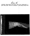
Fig. 5 illustrates Euler-code CFD analysis of an inlet incorporating the gradient pressure recovery structure of the invention. The various color gradients show the ram recovery distribution at the engine fan face for an inlet designed with a basic two dimensional ramp system (i.e. all compression ramp curvature generators occur along a series of stacked planes, with no curvature along planes perpendicular to the generating planes). The resulting pressure recovery distribution is banded with areas of highest pressure recovery (97-99%) occurring in the middle and areas of reduced recovery (91-97%) occurring along outer areas. - Non-uniform pressure recovery is un-avoidable in practical inlets with the additional effect of viscous boundary layers along the inlet walls. Non-uniform pressure recoveries tend to increase the fatigue of fan and compressor blades and reduce margins from stall or surge. All engines must be designed with some tolerance for non-uniform pressure distribution, on the order or less than 5 %. In this regard, a more circular ram recovery distribution is desired, and this is accomplished by providing 3-dimensional ramp curvature. A more desirable circular pattern is attainable by adding the slight reverse curvature in planes circumscribing over 180 degrees from the center of the inlet.
- The non-uniform analysis of ram recovery at Mach 1.6 for an inlet so designed is illustrated in
Fig. 6 . - Another benefit of the invention is greater stability from boundary layer effects, reducing or eliminating the need for terminal shock bleeds. By reaccelerating the inner flow behind the secondary oblique shock system, the boundary layer thickening or separation is stabilized. This is explained as follows: The reaccelerated flow passes through a relatively strong terminal shock and thickens or separates the boundary layer. The thickened boundary layer tends to strengthen the terminal shock and move it forward in the inlet, however the reverse curvature of the ramp tends to weaken the terminal shock as it moves forward, thus stabilizing the shock. The thickened or separated boundary layer behind this local shock area could cause an unacceptable pressure distortion to the engine and would need to be bled from the system, however compared to the conventional terminal shock bleed, it is bled downstream of the terminal shock system where much higher static pressure (and less sacrifice in total pressure) are available to induce the bleed flow.
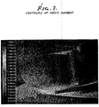
- This local shock system is illustrated in
Fig. 7 showing contours of Mach number in an isometric view of a 3-dimensionally designed inlet at Mach 1.5. At the peak of the compression ramp, it is seen that the flow reaccelerates locally over the peak and shocks down beyond it. If the flow were to be reduced, the terminal shock would travel up the ramp slightly, reducing the Mach number locally and weakening the terminal shock. - In the embodiment of the invention as seen in
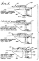
Figs. 1' and 2' , the inlet is separated laterally into three separate sections, a moveableforward inlet section 100, a secondmoveable bypass section 101 and athird section 102 fixed to theforward intake 103 of theengine 104. - Forward translation of the second section with respect to the third section opens an angled
aft facing slot 105 suitable for efficient bypassing of air in excess of the engine demand for high speed flight. The amount of air bypassed is regulated by the distance of translation of the second section with respect to the third. - Forward longitudinal translation of the most forward inlet section with respect to the second section exposes a rounded
blunt lip 106 at theleading edge 107 of thesecond section 101 suitable for efficient entrainment of additional air at low speeds about the periphery of the opening created by the separation of the two sections. - For medium cruise speeds (typically high subsonic through low supersonic speeds) the inlet is in a nominal closed position. In this position the bypass area defined by the
gap 107 between the second and third sections can be closed completely or allowed to always be open a small amount to induce a small bleed of inlet boundary layer air away from the engine for reduced flow distortion at the engine inlet. As the engine demand is reduced, either through increased speed or reduced power, the first and second sections translate forwardly together with respect to the third section, increasing the bypass opening and allowing excess inlet air to bypass to the outside surface. As the two sections translate forward, the first section (inlet) may be forced to tilt slightly with respect to the second section, thus tailoring the inlet's angle for the combination of Mach number and engine demand. This relative rotation can be accomplished via a track or linkage system, indicated generally at 109. Actuators are indicated generally at 110. - In the
Fig. 3' a)---d) embodiment the second section is held in contact with the first section via springs or elastic linkage 111 such that both would translate together for operation of the bypass. Mechanical stops are installed to limit the bypass opening to a maximum value, and additional translation imparted on the most forward inlet section operates to expose the low speedauxiliary opening 112. In this manner both bypass and low speed functions can be controlled by asingle actuator 110. In another embodiment, the inlet section and second section translation, and the inlet tilt angle are accomplished via independent actuators allowing complete control of the three functions separately. - In a further embodiment of the invention as seen in
Fig. 4' , the bypass, low speed, and inlet tilt angle are accomplished with two cowl sections, aforward inlet section 113 and a fixedaft section 114. In this case, the gap between the forward and aft sections incorporates geometry suitable for the bypass function when the sections are in close proximity to each other, and when separated further the wider gap between them provides the low speed auxiliary air function. As in the first embodiment, the relative angle of the forward inlet section relative to the aft section can be controlled via a track or linkage system, or controlled independently with an additional actuator system, indicated generally, at 115. -
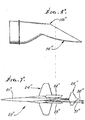
Fig. 1 " shows plug nozzle geometry, in a section taken along anengine center line 10", the cowl or nacelle indicated at 11". A nacelle boat tail or rearward angled wall is shown at 11"a, with drag occurring as at 13". Iso-Mach lines are shown at 44", and extend betweenrearward edge 11"b of the boat tail and aramp surface 14", along which exhaust expansion occurs. Flow lines are shown at 15". - The angle through which the flow must be turned is a function of the ratio of total pressure between the flow and local ambient conditions, with higher pressure ratios (and Mach numbers) requiring greater turning angles. The portion of the external duct curved inwards at the throat is known as the "boat tail". In supersonic flight the flow external to the duct will create a drag loss when it encounters the boat tail and is a function of the boat tail angle.
-
Figs. 2 " and3 " show asupersonic aircraft 20" having afuselage 21", and first andsecond jet engines 22" and 23", withnacelles 22"a and 23"a. The engines extend at generally opposite sides of thefuselage 21", and they may lapforwardly wing 24", having left andright sections 24"a and 24"b, which extend closest to the fuselage. An aircraft tail appears at 25". - The engines incorporate the
Fig. 1 " geometry, and are positioned so that theboat tail portions 11 "a are located laterally closer to the fuselage than the exhaust expansion ramps. SeeFig. 1 " showingfuselage side 21"a, with a relatively narrow or reducedflow gap 28" shown between 11"a and 21"a. The geometry is such that rearwardly directed thrust vectors are produced, as seen at 30" (for supersonic) and at 31", (for sub-sonic) inFig. 7 ". - Reduction in boat tail drag results from proximity to the fuselage body, shown by
line 21"a inFigs. 1 " and3 ", and as expanding cross sections alongcontour line 21"a. - In addition to the reduction in boat tail drag through the proximity to an expanding fuselage body, the invention provides the added benefit of reduced yawing moment and vertical tail size needed to counter an engine failure at low speed such as takeoff. This is due to the asymmetric characteristic of the thrust vector for different pressure ratios of the nozzle. This is illustrated in the flow vectors from CFD analysis of a nozzle geometry incorporating the surface expansion surface.
Fig. 5 " shows the flow paths for the nozzle operating at the high pressure ratio typical of supersonic operation. Here the nozzle is at design capacity and the flow is turned nearly in line with the freestream direction. - As the pressure ratio of the nozzle drops below its design point, such as for low speed conditions such as takeoff, the turn angle reduces and the flow tends to follow the expansion ramp angle, changing the direction of the thrust vector.
- For the nozzle arranged as described next to the fuselage, the net thrust vector is angled slightly inboard towards the center of gravity, reducing the yawing moment generated if the engine on one side is at reduced thrust compared to the other such as in an engine failed condition. This allows a vertical tail and rudder of reduced size to maintain control of the aircraft in low speed emergency engine failure conditions with requisite reduction in weight and drag.
- An additional benefit to the inward facing bevel nozzle configuration is the shielding effect of the fuselage and nozzle in reducing propagation of acoustic noise. It uses the fuselage and inward facing nozzle expansion surfaces to increase the effective length of the nozzle without added wetted area. These areas can be provided with acoustic liners for additional noise reduction.
- See also
Figs. 5 " and6 ". - The contours of the supersonic aircraft are preferably "area ruled", that is the contours of the aircraft bodies such as wings, fuselage, and nacelles are generated such as to smooth the combined cross-sectional areas of the bodies in such a way as to minimize the wave drag penalties of the complete configuration. Typically this involves reducing the cross-section of one body when it is in the vicinity of another body, the classic example being the "wasp waisting" of the fuselage where the wing intersects it. The nacelle containing the engine, air inlet system, and exhaust nozzle system represents a large cross-section. Wave drag is significantly reduced by further reducing the cross-section of the fuselage in near proximity to it.
-
Fig. 3 " is a close up view of the engine nacelle with inward facing "bevel" nozzle and its relationship to the fuselage. Adjacent to the maximum cross-section of the nacelle the fuselage is "waisted" (narrowed in cross section) in accordance with supersonic area rule considerations. Further aft, the nacelle cross-section reduces in the vicinity of the nozzle exit and the fuselage area expands as at 21 "a to maintain overall aircraft cross-section for area ruling. The expansion of the fuselage area adjacent to the nozzle aft end provides a surface angle symbiotic with the boat-tail angle needed for the nozzle exit, the combination reducing the drag of the boat-tail through its over-all integration with the full configuration area rule requirements. - Note in
Fig. 3 ", the following conditions: - 1) The fuselage has reduced lateral cross sections along the fuselage length at zones closest to the first and second jet engine nacelles.
- 2) The reduced cross sections of the fuselage relative to the first and second jet engine nacelles define an area ruled configuration or configurations.
- 3) The reduced cross sections of the fuselage relative to both jet engine nacelles and to the wing section or sections closest to the fuselage define an area ruled configuration or configurations.
- 4) The
gap 60" between the engine nacelle and the fuselage side is typically less in width than the engine nacelle width, laterally outwardly of the gap, at lateral stations lengthwise of the gap.
Claims (11)
- A supersonic aircraft jet engine installation having engine inlet structure comprising:an inlet ramp and a cowl having a lip (43) spaced outwardly of the ramp so that entering air flows between the ramp and lip, characterized in that ramp is configured to produce a first oblique shock system (42) that extends outwardly from a forward portion of the ramp to pass ahead of the lip (43), a second oblique shock system (47) that extends outwardly from said ramp aft of said first oblique shock system (42) to intersection within the lip with a terminal shock (49) that extends outwardly from a rearward portion of the ramp, the ramp in axial radial planes in the flow direction having:a first portion (41) that has outward concavity;a second portion (44) which is straight and configured to produce said first oblique shock system (42) that extends generally forward of said lip and within the flow path of air through the inlet structure providing substantially no additional compression;a third portion (45) located rearwardly of said second portion (44), said third portion (45) being outwardly concave and configured to produce an oblique shock system (47) that extends from said third portion (45) toward a part (at 50) of said terminal shock (49) that is spaced from the lip (43);a fourth portion (52) that is straight and follows said third portion (45), close to the terminal shock (49); anda fifth portion (54) providing initial turning of the flow towards the engine ahead of the terminal shock (49), said fifth portion (54) extending uninterruptedly from said fourth portion (52), said inlet system creating a compression and shock system and total pressure distribution that is intentionally non-uniform across any axial plane located rearwardly of the terminal shock.
- The installation of claim 1, further comprising an inlet cowl assembly having forward and rearward separable in line air intake sections (100, 102); said in line air intake sections having primary relatively closed positions and secondary relatively separated positions to provide an air passing gap (112) therebetween; and means (109, 110) for controlling relative tilt of the in line air intake sections to controllably vary the geometry of said air passing gap.
- The installation of claim 2, wherein said cowl assembly has three separate generally tubular sections including a forward inlet section (100), a bypass section (101) and a fixed section (102), said forward inlet section being forwardly translatable relative to said bypass section, and said bypass section being forwardly translatable relative to said fixed section, said inlet section having a forward position everywhere openly spaced entirely forwardly of the bypass section.
- The installation of claim 3, wherein the bypass section (101) has an arcuately blunted leading edge exposed for efficient entrainment of additional intake air at low aircraft speeds, in response to said inlet section translation forwardly with respect to said bypass section.
- The installation of claim 2, 3 or 4, wherein said means for controlling relative tilt includes an actuator (110) operatively connected to the forward cowl section (100) to vary tilt thereof relative to the bypass section (101).
- The installation of claim 5, wherein the inlet and bypass sections have simultaneously forwardly translated positions, relative to the fixed section, whereby a circumferential opening between the bypass and fixed sections is increased to allow excess inlet air to bypass to the exterior.
- The installation of claim 4, 5 or 6, wherein the inlet section has a tilt position relative to the bypass section as the inlet and bypass sections are translated forwardly.
- An aircraft comprising the installation of any one of the preceding claims, including engines (22", 23") having nacelles (22"a, 23"a), a fuselage (21) and wings (14), the nacelles and cowls having forward portions lapping the wings and located proximate the sides of the fuselage.
- The aircraft of claim 8, wherein the sides of the fuselage facing the nacelles have reduced cross sections along fuselage length at zones closest to forwardmost portions of said nacelles.
- The aircraft of claim 8 or 9, wherein said nacelles have boat tail portions (11a") and exhaust expansion ramps (14"), said boat tail portions located laterally closer to the fuselage (21) than the expansion ramps, and wherein the nacelles have rearwardmost looping edges defining nozzle outlets, said edges angled forwardly and toward the fuselage.
- The aircraft of claim 9, wherein the wings, nacelles and reduced cross sections of the fuselage define an area ruled configuration.
Applications Claiming Priority (4)
| Application Number | Priority Date | Filing Date | Title |
|---|---|---|---|
| US85184106P | 2006-10-12 | 2006-10-12 | |
| US85163006P | 2006-10-13 | 2006-10-13 | |
| US85140306P | 2006-10-13 | 2006-10-13 | |
| PCT/US2007/021624 WO2008105847A2 (en) | 2006-10-12 | 2007-10-10 | Supersonic aircraft jet engine |
Publications (3)
| Publication Number | Publication Date |
|---|---|
| EP2084061A2 EP2084061A2 (en) | 2009-08-05 |
| EP2084061A4 EP2084061A4 (en) | 2013-07-24 |
| EP2084061B1 true EP2084061B1 (en) | 2016-12-14 |
Family
ID=39721729
Family Applications (1)
| Application Number | Title | Priority Date | Filing Date |
|---|---|---|---|
| EP07873759.0A Not-in-force EP2084061B1 (en) | 2006-10-12 | 2007-10-10 | Supersonic aircraft jet engine |
Country Status (6)
| Country | Link |
|---|---|
| US (3) | US7837142B2 (en) |
| EP (1) | EP2084061B1 (en) |
| CA (1) | CA2665848C (en) |
| ES (1) | ES2617754T3 (en) |
| RU (2) | RU2499739C2 (en) |
| WO (1) | WO2008105847A2 (en) |
Cited By (1)
| Publication number | Priority date | Publication date | Assignee | Title |
|---|---|---|---|---|
| US11834154B2 (en) | 2015-09-22 | 2023-12-05 | Nctar, Llc | Shockwave mitigation system for supersonic aircraft |
Families Citing this family (30)
| Publication number | Priority date | Publication date | Assignee | Title |
|---|---|---|---|---|
| JP4846808B2 (en) * | 2005-12-15 | 2011-12-28 | ガルフストリーム・エアロスペース・コーポレイション | Isentropic compression inlet for supersonic aircraft |
| US7837142B2 (en) * | 2006-10-12 | 2010-11-23 | Aerion Corporation | Supersonic aircraft jet engine |
| US8393158B2 (en) | 2007-10-24 | 2013-03-12 | Gulfstream Aerospace Corporation | Low shock strength inlet |
| FR2937952B1 (en) * | 2008-10-30 | 2010-12-17 | Snecma | AIRCRAFT WITH PARTIALLY INTEGRATED ENGINES IN FUSELAGE |
| US8192158B1 (en) * | 2008-12-12 | 2012-06-05 | Mainstream Engineering Corp. | Apparatus and method to increase total-to-static pressure ratio across a turbine |
| US8794902B1 (en) | 2010-01-26 | 2014-08-05 | II Daniel K. Van Ness | System and method to improve the exhaust pressure across a RAM air turbine through secondary flow mixing |
| US9121369B2 (en) | 2011-08-19 | 2015-09-01 | Gulfstream Aerospace Corporation | Nozzle arrangement and method of making the same |
| US9353704B2 (en) | 2011-08-19 | 2016-05-31 | Gulfstream Aerospace Corporation | Air inlet arrangement and method of making the same |
| US20130213481A1 (en) * | 2011-10-05 | 2013-08-22 | Gohypersonic, Inc. | Self-starting supersonic inlet |
| US8690097B1 (en) | 2012-04-30 | 2014-04-08 | The Boeing Company | Variable-geometry rotating spiral cone engine inlet compression system and method |
| RU2521164C1 (en) * | 2012-11-20 | 2014-06-27 | Закрытое акционерное общество "Новые гражданские технологии Сухого" | Aircraft |
| RU2517629C1 (en) * | 2012-11-20 | 2014-05-27 | Закрытое акционерное общество "Новые гражданские технологии Сухого" | Aircraft |
| US9884688B2 (en) | 2013-02-14 | 2018-02-06 | Gulfstream Aerospace Corporation | Propulsion system using large scale vortex generators for flow redistribution and supersonic aircraft equipped with the propulsion system |
| US9009966B2 (en) | 2013-03-15 | 2015-04-21 | Northrop Gurmman Systems Corporation | Internal/external single expansion ramp nozzle with integrated third stream |
| US9908633B2 (en) * | 2015-03-31 | 2018-03-06 | The Boeing Company | Variable-capture supersonic inlet |
| US9758253B2 (en) | 2015-06-25 | 2017-09-12 | Northrop Grumman Systems Corporation | Swept gradient boundary layer diverter |
| US9725155B2 (en) | 2015-12-30 | 2017-08-08 | General Electric Company | Method and system for open rotor engine fuselage protection |
| US10220952B2 (en) | 2016-08-24 | 2019-03-05 | General Electric Company | Nacelle for an aircraft aft fan |
| US10724472B1 (en) | 2017-06-16 | 2020-07-28 | Aerion Intellectual Property Management Corporation | High flow plug nozzle apparatus and method of using the same |
| RU2687437C1 (en) * | 2018-10-31 | 2019-05-14 | Дмитрий Дмитриевич Кожевников | Double supersonic convergent air intake (dscai) |
| US11390393B2 (en) | 2019-06-04 | 2022-07-19 | Rohr, Inc. | Nacelle with a translatable inlet for an aircraft propulsion system |
| US11441482B2 (en) | 2019-06-04 | 2022-09-13 | Rohr, Inc. | Single track translating inlet |
| RU196781U1 (en) * | 2019-12-03 | 2020-03-16 | Федеральное государственное унитарное предприятие "Центральный аэрогидродинамический институт имени профессора Н.Е. Жуковского" (ФГУП "ЦАГИ") | Air intake supersonic passenger aircraft |
| RU196778U1 (en) * | 2019-12-03 | 2020-03-16 | Федеральное государственное унитарное предприятие "Центральный аэрогидродинамический институт имени профессора Н.Е. Жуковского" (ФГУП "ЦАГИ") | Air intake supersonic passenger aircraft |
| CN111516871A (en) * | 2020-04-30 | 2020-08-11 | 浙江大学 | Supersonic stealth unmanned aerial vehicle with pneumatic stealth integrated design |
| RU2747333C1 (en) * | 2020-06-18 | 2021-05-04 | Российская Федерация, от имени которой выступает Министерство обороны Российской Федерации | Air intake device of a supersonic ramjet engine integrated with the aircraft body |
| US11560841B2 (en) | 2021-06-25 | 2023-01-24 | Rohr, Inc. | Aircraft propulsion system with variable area inlet |
| US11725581B2 (en) | 2021-06-25 | 2023-08-15 | Rohr, Inc. | Aircraft propulsion system with variable area inlet |
| US11767124B2 (en) | 2021-09-10 | 2023-09-26 | Rohr, Inc. | Aircraft propulsion system with variable area inlet |
| US11840985B2 (en) | 2021-09-10 | 2023-12-12 | Rohr, Inc. | Aircraft propulsion system with variable area inlet |
Family Cites Families (33)
| Publication number | Priority date | Publication date | Assignee | Title |
|---|---|---|---|---|
| GB967720A (en) | 1955-11-07 | 1964-08-26 | Commw Of Australia | Improvements in and connected with supersonic air intakes |
| FR1204525A (en) | 1958-04-12 | 1960-01-26 | Improvements to tunnel-shaped aircrafts, particularly those with vertical take-off and landing | |
| DE1078375B (en) | 1958-08-08 | 1960-03-24 | Ernst Heinkel Flugzeugbau G M | Adjustable air intake especially for jet engines |
| GB856507A (en) | 1959-04-21 | 1960-12-21 | Gen Electric | Improvements in supersonic airfoil |
| US3242671A (en) * | 1964-04-08 | 1966-03-29 | Boeing Co | Fixed spike inlet with variable throat and capture area |
| GB1077196A (en) | 1966-04-26 | 1967-07-26 | Rolls Royce | Air intake duct for a gas turbine engine |
| US3489375A (en) | 1967-11-21 | 1970-01-13 | Richard R Tracy | Variable lifting surface craft |
| US3498375A (en) * | 1968-01-04 | 1970-03-03 | Moore Corp Lee C | Oil well derrick substructure with blowout preventer dolly |
| SU547089A1 (en) * | 1975-05-11 | 2005-04-20 | Ю.Ф. Ершов | AIR PRESSURE RECEIVER |
| US4007891A (en) * | 1975-09-12 | 1977-02-15 | The United States Of America As Represented By The Administrator Of The National Aeronautics And Space Administration | Jet engine air intake system |
| US4372505A (en) * | 1979-12-17 | 1983-02-08 | The Boeing Company | Supersonic inlet having variable area sideplate openings |
| US4620679A (en) * | 1984-08-02 | 1986-11-04 | United Technologies Corporation | Variable-geometry inlet |
| DE3811614C1 (en) * | 1988-04-07 | 1989-05-18 | Messerschmitt-Boelkow-Blohm Gmbh, 8012 Ottobrunn, De | |
| FR2635075B1 (en) * | 1988-08-04 | 1994-09-23 | Onera (Off Nat Aerospatiale) | TWO-DIMENSIONAL AND ASYMMETRIC SUPERSONIC AIR INLET FOR COMBUSTION AIR OF AN AIRCRAFT ENGINE |
| DE3942022A1 (en) * | 1989-12-20 | 1991-06-27 | Mtu Muenchen Gmbh | METHOD AND DEVICE FOR COOLING AN AIRCRAFT ENGINE |
| US5826424A (en) * | 1992-04-16 | 1998-10-27 | Klees; Garry W. | Turbine bypass engines |
| DE4222947C2 (en) | 1992-07-11 | 1995-02-02 | Deutsche Aerospace | Jet engine |
| FR2710607B1 (en) * | 1993-10-01 | 1995-12-01 | Onera (Off Nat Aerospatiale) | Two-dimensional supersonic and hypersonic air inlet, with three movable ramps, for the combustion air of an aircraft engine. |
| US5706649A (en) * | 1995-04-03 | 1998-01-13 | Boeing North American, Inc. | Multi axis thrust vectoring for turbo fan engines |
| FR2763098B1 (en) * | 1997-05-07 | 1999-06-11 | Snecma | AIR INTAKE SYSTEM IN A TURBOMACHINE VEIN |
| US5987880A (en) * | 1997-07-08 | 1999-11-23 | Mcdonnell Douglas Corporation | Supersonic engine, multi-port thrust reversing system |
| RU2171211C2 (en) * | 1997-12-29 | 2001-07-27 | Медведев Владимир Тимофеевич | Self-adjustable air intake |
| US6276632B1 (en) * | 1998-09-16 | 2001-08-21 | Bobby W. Sanders | Axi-symmetric mixed compression inlet with variable geometry centerbody |
| USD417184S (en) * | 1999-03-02 | 1999-11-30 | Lockheed Martin Corporation | Supersonic business jet |
| US6793175B1 (en) * | 1999-08-25 | 2004-09-21 | The Boeing Company | Supersonic external-compression diffuser and method for designing same |
| US6575406B2 (en) * | 2001-01-19 | 2003-06-10 | The Boeing Company | Integrated and/or modular high-speed aircraft |
| US6920890B2 (en) * | 2001-07-30 | 2005-07-26 | Techland Research, Inc. | Airflow controller |
| US6634595B2 (en) * | 2002-01-11 | 2003-10-21 | The Boeing Company | Method and apparatus for controlling aircraft inlet air flow |
| US6651928B1 (en) * | 2002-09-05 | 2003-11-25 | The Boeing Company | Aircraft engine nacelles and methods for their manufacture |
| US6969028B2 (en) | 2003-01-22 | 2005-11-29 | The Boeing Company | Scarf nozzle for a jet engine and method of using the same |
| US6910327B2 (en) * | 2003-07-28 | 2005-06-28 | The Boeing Company | Apparatus and methods for varying inlet lip geometry of a jet engine inlet |
| US7837142B2 (en) * | 2006-10-12 | 2010-11-23 | Aerion Corporation | Supersonic aircraft jet engine |
| US7762077B2 (en) * | 2006-12-05 | 2010-07-27 | Pratt & Whitney Rocketdyne, Inc. | Single-stage hypersonic vehicle featuring advanced swirl combustion |
-
2007
- 2007-10-09 US US11/973,813 patent/US7837142B2/en active Active - Reinstated
- 2007-10-10 ES ES07873759.0T patent/ES2617754T3/en active Active
- 2007-10-10 WO PCT/US2007/021624 patent/WO2008105847A2/en active Application Filing
- 2007-10-10 CA CA2665848A patent/CA2665848C/en not_active Expired - Fee Related
- 2007-10-10 EP EP07873759.0A patent/EP2084061B1/en not_active Not-in-force
- 2007-10-10 RU RU2011150809/11A patent/RU2499739C2/en active
-
2010
- 2010-08-30 US US12/807,154 patent/US20220073203A1/en not_active Abandoned
- 2010-08-30 US US12/807,142 patent/US7967241B2/en active Active
-
2011
- 2011-12-13 RU RU2011150806/02A patent/RU2011150806A/en not_active Application Discontinuation
Cited By (1)
| Publication number | Priority date | Publication date | Assignee | Title |
|---|---|---|---|---|
| US11834154B2 (en) | 2015-09-22 | 2023-12-05 | Nctar, Llc | Shockwave mitigation system for supersonic aircraft |
Also Published As
| Publication number | Publication date |
|---|---|
| RU2011150806A (en) | 2013-06-20 |
| CA2665848C (en) | 2015-12-01 |
| RU2499739C2 (en) | 2013-11-27 |
| WO2008105847A3 (en) | 2008-11-06 |
| US7967241B2 (en) | 2011-06-28 |
| US7837142B2 (en) | 2010-11-23 |
| RU2011150809A (en) | 2013-06-20 |
| WO2008105847A2 (en) | 2008-09-04 |
| CA2665848A1 (en) | 2008-09-04 |
| US20090014597A1 (en) | 2009-01-15 |
| ES2617754T3 (en) | 2017-06-19 |
| EP2084061A4 (en) | 2013-07-24 |
| US20110062290A1 (en) | 2011-03-17 |
| EP2084061A2 (en) | 2009-08-05 |
| US20220073203A1 (en) | 2022-03-10 |
Similar Documents
| Publication | Publication Date | Title |
|---|---|---|
| EP2084061B1 (en) | Supersonic aircraft jet engine | |
| EP1206384B1 (en) | Supersonic external-compression diffuser and method for designing same | |
| CA2703602C (en) | Low shock strength propulsion system | |
| US6575406B2 (en) | Integrated and/or modular high-speed aircraft | |
| EP1243782B2 (en) | Double jet engine inlet | |
| US4620679A (en) | Variable-geometry inlet | |
| US4463772A (en) | Flush inlet for supersonic aircraft | |
| CA2664244C (en) | Aircraft engine nacelle and aircraft equipped with such a nacelle | |
| JPH0737240B2 (en) | Mixed laminar flow nacelle | |
| EP2350445B1 (en) | Method and system for altering engine air intake geometry | |
| EP3112650B1 (en) | Inlet flow restrictor | |
| US11486306B2 (en) | Flush fluid inlet designs for aero-acoustic tone mitigation of aircraft | |
| RU2454354C2 (en) | Supersonic aircraft jet engine | |
| US11772779B2 (en) | Propulsion unit with improved boundary layer ingestion | |
| EP2180164A1 (en) | Method and system for altering engine air intake geometry | |
| US20230174231A1 (en) | Airfoil With Supersonic Wave-Tripping Structure | |
| Silverman | Aircraft pay-offs and requirements for a jet flap propulsion system | |
| AU2002309481A1 (en) | Integrated and/or modular high-speed aircraft |
Legal Events
| Date | Code | Title | Description |
|---|---|---|---|
| PUAI | Public reference made under article 153(3) epc to a published international application that has entered the european phase |
Free format text: ORIGINAL CODE: 0009012 |
|
| 17P | Request for examination filed |
Effective date: 20090421 |
|
| AK | Designated contracting states |
Kind code of ref document: A2 Designated state(s): AT BE BG CH CY CZ DE DK EE ES FI FR GB GR HU IE IS IT LI LT LU LV MC MT NL PL PT RO SE SI SK TR |
|
| RIN1 | Information on inventor provided before grant (corrected) |
Inventor name: CHASE, JAMES, D. Inventor name: GARZON, GERMAN, ANDRES |
|
| DAX | Request for extension of the european patent (deleted) | ||
| A4 | Supplementary search report drawn up and despatched |
Effective date: 20130625 |
|
| RIC1 | Information provided on ipc code assigned before grant |
Ipc: B64C 30/00 20060101AFI20130619BHEP |
|
| 17Q | First examination report despatched |
Effective date: 20140203 |
|
| GRAP | Despatch of communication of intention to grant a patent |
Free format text: ORIGINAL CODE: EPIDOSNIGR1 |
|
| INTG | Intention to grant announced |
Effective date: 20160524 |
|
| GRAS | Grant fee paid |
Free format text: ORIGINAL CODE: EPIDOSNIGR3 |
|
| GRAA | (expected) grant |
Free format text: ORIGINAL CODE: 0009210 |
|
| AK | Designated contracting states |
Kind code of ref document: B1 Designated state(s): AT BE BG CH CY CZ DE DK EE ES FI FR GB GR HU IE IS IT LI LT LU LV MC MT NL PL PT RO SE SI SK TR |
|
| REG | Reference to a national code |
Ref country code: GB Ref legal event code: FG4D |
|
| REG | Reference to a national code |
Ref country code: CH Ref legal event code: EP |
|
| REG | Reference to a national code |
Ref country code: IE Ref legal event code: FG4D |
|
| REG | Reference to a national code |
Ref country code: AT Ref legal event code: REF Ref document number: 853311 Country of ref document: AT Kind code of ref document: T Effective date: 20170115 |
|
| REG | Reference to a national code |
Ref country code: DE Ref legal event code: R096 Ref document number: 602007049183 Country of ref document: DE |
|
| PG25 | Lapsed in a contracting state [announced via postgrant information from national office to epo] |
Ref country code: LV Free format text: LAPSE BECAUSE OF FAILURE TO SUBMIT A TRANSLATION OF THE DESCRIPTION OR TO PAY THE FEE WITHIN THE PRESCRIBED TIME-LIMIT Effective date: 20161214 |
|
| REG | Reference to a national code |
Ref country code: LT Ref legal event code: MG4D |
|
| REG | Reference to a national code |
Ref country code: NL Ref legal event code: MP Effective date: 20161214 |
|
| PG25 | Lapsed in a contracting state [announced via postgrant information from national office to epo] |
Ref country code: LT Free format text: LAPSE BECAUSE OF FAILURE TO SUBMIT A TRANSLATION OF THE DESCRIPTION OR TO PAY THE FEE WITHIN THE PRESCRIBED TIME-LIMIT Effective date: 20161214 Ref country code: SE Free format text: LAPSE BECAUSE OF FAILURE TO SUBMIT A TRANSLATION OF THE DESCRIPTION OR TO PAY THE FEE WITHIN THE PRESCRIBED TIME-LIMIT Effective date: 20161214 Ref country code: GR Free format text: LAPSE BECAUSE OF FAILURE TO SUBMIT A TRANSLATION OF THE DESCRIPTION OR TO PAY THE FEE WITHIN THE PRESCRIBED TIME-LIMIT Effective date: 20170315 |
|
| REG | Reference to a national code |
Ref country code: AT Ref legal event code: MK05 Ref document number: 853311 Country of ref document: AT Kind code of ref document: T Effective date: 20161214 |
|
| PG25 | Lapsed in a contracting state [announced via postgrant information from national office to epo] |
Ref country code: FI Free format text: LAPSE BECAUSE OF FAILURE TO SUBMIT A TRANSLATION OF THE DESCRIPTION OR TO PAY THE FEE WITHIN THE PRESCRIBED TIME-LIMIT Effective date: 20161214 |
|
| REG | Reference to a national code |
Ref country code: ES Ref legal event code: FG2A Ref document number: 2617754 Country of ref document: ES Kind code of ref document: T3 Effective date: 20170619 |
|
| PG25 | Lapsed in a contracting state [announced via postgrant information from national office to epo] |
Ref country code: NL Free format text: LAPSE BECAUSE OF FAILURE TO SUBMIT A TRANSLATION OF THE DESCRIPTION OR TO PAY THE FEE WITHIN THE PRESCRIBED TIME-LIMIT Effective date: 20161214 |
|
| REG | Reference to a national code |
Ref country code: FR Ref legal event code: PLFP Year of fee payment: 11 |
|
| PG25 | Lapsed in a contracting state [announced via postgrant information from national office to epo] |
Ref country code: RO Free format text: LAPSE BECAUSE OF FAILURE TO SUBMIT A TRANSLATION OF THE DESCRIPTION OR TO PAY THE FEE WITHIN THE PRESCRIBED TIME-LIMIT Effective date: 20161214 Ref country code: IS Free format text: LAPSE BECAUSE OF FAILURE TO SUBMIT A TRANSLATION OF THE DESCRIPTION OR TO PAY THE FEE WITHIN THE PRESCRIBED TIME-LIMIT Effective date: 20170414 Ref country code: SK Free format text: LAPSE BECAUSE OF FAILURE TO SUBMIT A TRANSLATION OF THE DESCRIPTION OR TO PAY THE FEE WITHIN THE PRESCRIBED TIME-LIMIT Effective date: 20161214 Ref country code: EE Free format text: LAPSE BECAUSE OF FAILURE TO SUBMIT A TRANSLATION OF THE DESCRIPTION OR TO PAY THE FEE WITHIN THE PRESCRIBED TIME-LIMIT Effective date: 20161214 Ref country code: CZ Free format text: LAPSE BECAUSE OF FAILURE TO SUBMIT A TRANSLATION OF THE DESCRIPTION OR TO PAY THE FEE WITHIN THE PRESCRIBED TIME-LIMIT Effective date: 20161214 |
|
| PG25 | Lapsed in a contracting state [announced via postgrant information from national office to epo] |
Ref country code: PT Free format text: LAPSE BECAUSE OF FAILURE TO SUBMIT A TRANSLATION OF THE DESCRIPTION OR TO PAY THE FEE WITHIN THE PRESCRIBED TIME-LIMIT Effective date: 20170414 Ref country code: BE Free format text: LAPSE BECAUSE OF FAILURE TO SUBMIT A TRANSLATION OF THE DESCRIPTION OR TO PAY THE FEE WITHIN THE PRESCRIBED TIME-LIMIT Effective date: 20161214 Ref country code: BG Free format text: LAPSE BECAUSE OF FAILURE TO SUBMIT A TRANSLATION OF THE DESCRIPTION OR TO PAY THE FEE WITHIN THE PRESCRIBED TIME-LIMIT Effective date: 20170314 Ref country code: AT Free format text: LAPSE BECAUSE OF FAILURE TO SUBMIT A TRANSLATION OF THE DESCRIPTION OR TO PAY THE FEE WITHIN THE PRESCRIBED TIME-LIMIT Effective date: 20161214 Ref country code: IT Free format text: LAPSE BECAUSE OF FAILURE TO SUBMIT A TRANSLATION OF THE DESCRIPTION OR TO PAY THE FEE WITHIN THE PRESCRIBED TIME-LIMIT Effective date: 20161214 Ref country code: PL Free format text: LAPSE BECAUSE OF FAILURE TO SUBMIT A TRANSLATION OF THE DESCRIPTION OR TO PAY THE FEE WITHIN THE PRESCRIBED TIME-LIMIT Effective date: 20161214 |
|
| REG | Reference to a national code |
Ref country code: DE Ref legal event code: R097 Ref document number: 602007049183 Country of ref document: DE |
|
| PLBE | No opposition filed within time limit |
Free format text: ORIGINAL CODE: 0009261 |
|
| STAA | Information on the status of an ep patent application or granted ep patent |
Free format text: STATUS: NO OPPOSITION FILED WITHIN TIME LIMIT |
|
| 26N | No opposition filed |
Effective date: 20170915 |
|
| PG25 | Lapsed in a contracting state [announced via postgrant information from national office to epo] |
Ref country code: DK Free format text: LAPSE BECAUSE OF FAILURE TO SUBMIT A TRANSLATION OF THE DESCRIPTION OR TO PAY THE FEE WITHIN THE PRESCRIBED TIME-LIMIT Effective date: 20161214 |
|
| PG25 | Lapsed in a contracting state [announced via postgrant information from national office to epo] |
Ref country code: SI Free format text: LAPSE BECAUSE OF FAILURE TO SUBMIT A TRANSLATION OF THE DESCRIPTION OR TO PAY THE FEE WITHIN THE PRESCRIBED TIME-LIMIT Effective date: 20161214 |
|
| PG25 | Lapsed in a contracting state [announced via postgrant information from national office to epo] |
Ref country code: MC Free format text: LAPSE BECAUSE OF FAILURE TO SUBMIT A TRANSLATION OF THE DESCRIPTION OR TO PAY THE FEE WITHIN THE PRESCRIBED TIME-LIMIT Effective date: 20161214 |
|
| REG | Reference to a national code |
Ref country code: CH Ref legal event code: PL |
|
| REG | Reference to a national code |
Ref country code: IE Ref legal event code: MM4A |
|
| PG25 | Lapsed in a contracting state [announced via postgrant information from national office to epo] |
Ref country code: CH Free format text: LAPSE BECAUSE OF NON-PAYMENT OF DUE FEES Effective date: 20171031 Ref country code: LU Free format text: LAPSE BECAUSE OF NON-PAYMENT OF DUE FEES Effective date: 20171010 Ref country code: LI Free format text: LAPSE BECAUSE OF NON-PAYMENT OF DUE FEES Effective date: 20171031 |
|
| REG | Reference to a national code |
Ref country code: ES Ref legal event code: PC2A Owner name: AERION INTELLECTUAL PROPERTY MANAGEMENT CORPORATIO Effective date: 20180809 Ref legal event code: PC2A Effective date: 20180809 |
|
| REG | Reference to a national code |
Ref country code: GB Ref legal event code: 732E Free format text: REGISTERED BETWEEN 20180726 AND 20180801 |
|
| REG | Reference to a national code |
Ref country code: FR Ref legal event code: PLFP Year of fee payment: 12 |
|
| PG25 | Lapsed in a contracting state [announced via postgrant information from national office to epo] |
Ref country code: MT Free format text: LAPSE BECAUSE OF NON-PAYMENT OF DUE FEES Effective date: 20171010 |
|
| PG25 | Lapsed in a contracting state [announced via postgrant information from national office to epo] |
Ref country code: IE Free format text: LAPSE BECAUSE OF NON-PAYMENT OF DUE FEES Effective date: 20171010 |
|
| PG25 | Lapsed in a contracting state [announced via postgrant information from national office to epo] |
Ref country code: HU Free format text: LAPSE BECAUSE OF FAILURE TO SUBMIT A TRANSLATION OF THE DESCRIPTION OR TO PAY THE FEE WITHIN THE PRESCRIBED TIME-LIMIT; INVALID AB INITIO Effective date: 20071010 |
|
| PG25 | Lapsed in a contracting state [announced via postgrant information from national office to epo] |
Ref country code: CY Free format text: LAPSE BECAUSE OF NON-PAYMENT OF DUE FEES Effective date: 20161214 |
|
| PG25 | Lapsed in a contracting state [announced via postgrant information from national office to epo] |
Ref country code: TR Free format text: LAPSE BECAUSE OF FAILURE TO SUBMIT A TRANSLATION OF THE DESCRIPTION OR TO PAY THE FEE WITHIN THE PRESCRIBED TIME-LIMIT Effective date: 20161214 |
|
| PGFP | Annual fee paid to national office [announced via postgrant information from national office to epo] |
Ref country code: FR Payment date: 20200916 Year of fee payment: 14 Ref country code: GB Payment date: 20200911 Year of fee payment: 14 |
|
| PGFP | Annual fee paid to national office [announced via postgrant information from national office to epo] |
Ref country code: ES Payment date: 20201105 Year of fee payment: 14 Ref country code: DE Payment date: 20201026 Year of fee payment: 14 |
|
| REG | Reference to a national code |
Ref country code: DE Ref legal event code: R119 Ref document number: 602007049183 Country of ref document: DE |
|
| GBPC | Gb: european patent ceased through non-payment of renewal fee |
Effective date: 20211010 |
|
| PG25 | Lapsed in a contracting state [announced via postgrant information from national office to epo] |
Ref country code: GB Free format text: LAPSE BECAUSE OF NON-PAYMENT OF DUE FEES Effective date: 20211010 Ref country code: DE Free format text: LAPSE BECAUSE OF NON-PAYMENT OF DUE FEES Effective date: 20220503 |
|
| PG25 | Lapsed in a contracting state [announced via postgrant information from national office to epo] |
Ref country code: FR Free format text: LAPSE BECAUSE OF NON-PAYMENT OF DUE FEES Effective date: 20211031 |
|
| REG | Reference to a national code |
Ref country code: ES Ref legal event code: FD2A Effective date: 20230203 |
|
| PG25 | Lapsed in a contracting state [announced via postgrant information from national office to epo] |
Ref country code: ES Free format text: LAPSE BECAUSE OF NON-PAYMENT OF DUE FEES Effective date: 20211011 |