EP0940338A2 - Gearbox breather outlet - Google Patents
Gearbox breather outlet Download PDFInfo
- Publication number
- EP0940338A2 EP0940338A2 EP99300890A EP99300890A EP0940338A2 EP 0940338 A2 EP0940338 A2 EP 0940338A2 EP 99300890 A EP99300890 A EP 99300890A EP 99300890 A EP99300890 A EP 99300890A EP 0940338 A2 EP0940338 A2 EP 0940338A2
- Authority
- EP
- European Patent Office
- Prior art keywords
- breather
- mast
- outlet
- exhaust outlet
- nacelle
- Prior art date
- Legal status (The legal status is an assumption and is not a legal conclusion. Google has not performed a legal analysis and makes no representation as to the accuracy of the status listed.)
- Granted
Links
- 230000004323 axial length Effects 0.000 claims description 4
- 230000004888 barrier function Effects 0.000 claims description 3
- 238000010186 staining Methods 0.000 abstract description 2
- 239000000203 mixture Substances 0.000 description 8
- 239000003595 mist Substances 0.000 description 4
- 238000011144 upstream manufacturing Methods 0.000 description 4
- 239000002184 metal Substances 0.000 description 2
- OKTJSMMVPCPJKN-UHFFFAOYSA-N Carbon Chemical compound [C] OKTJSMMVPCPJKN-UHFFFAOYSA-N 0.000 description 1
- 229910000831 Steel Inorganic materials 0.000 description 1
- 230000001154 acute effect Effects 0.000 description 1
- 238000013019 agitation Methods 0.000 description 1
- 238000004140 cleaning Methods 0.000 description 1
- 230000000694 effects Effects 0.000 description 1
- 239000000835 fiber Substances 0.000 description 1
- 229910002804 graphite Inorganic materials 0.000 description 1
- 239000010439 graphite Substances 0.000 description 1
- 230000003993 interaction Effects 0.000 description 1
- 239000000463 material Substances 0.000 description 1
- 238000000034 method Methods 0.000 description 1
- 230000001141 propulsive effect Effects 0.000 description 1
- 239000011208 reinforced composite material Substances 0.000 description 1
- 239000002990 reinforced plastic Substances 0.000 description 1
- 230000000717 retained effect Effects 0.000 description 1
- 238000000926 separation method Methods 0.000 description 1
- 239000010959 steel Substances 0.000 description 1
- 230000007704 transition Effects 0.000 description 1
- 238000003466 welding Methods 0.000 description 1
Images

Classifications
-
- B—PERFORMING OPERATIONS; TRANSPORTING
- B64—AIRCRAFT; AVIATION; COSMONAUTICS
- B64C—AEROPLANES; HELICOPTERS
- B64C23/00—Influencing air flow over aircraft surfaces, not otherwise provided for
- B64C23/06—Influencing air flow over aircraft surfaces, not otherwise provided for by generating vortices
-
- B—PERFORMING OPERATIONS; TRANSPORTING
- B64—AIRCRAFT; AVIATION; COSMONAUTICS
- B64C—AEROPLANES; HELICOPTERS
- B64C1/00—Fuselages; Constructional features common to fuselages, wings, stabilising surfaces or the like
- B64C1/14—Windows; Doors; Hatch covers or access panels; Surrounding frame structures; Canopies; Windscreens accessories therefor, e.g. pressure sensors, water deflectors, hinges, seals, handles, latches, windscreen wipers
- B64C1/1407—Doors; surrounding frames
- B64C1/1453—Drain masts
-
- B—PERFORMING OPERATIONS; TRANSPORTING
- B64—AIRCRAFT; AVIATION; COSMONAUTICS
- B64D—EQUIPMENT FOR FITTING IN OR TO AIRCRAFT; FLIGHT SUITS; PARACHUTES; ARRANGEMENT OR MOUNTING OF POWER PLANTS OR PROPULSION TRANSMISSIONS IN AIRCRAFT
- B64D33/00—Arrangement in aircraft of power plant parts or auxiliaries not otherwise provided for
- B64D33/04—Arrangement in aircraft of power plant parts or auxiliaries not otherwise provided for of exhaust outlets or jet pipes
-
- Y—GENERAL TAGGING OF NEW TECHNOLOGICAL DEVELOPMENTS; GENERAL TAGGING OF CROSS-SECTIONAL TECHNOLOGIES SPANNING OVER SEVERAL SECTIONS OF THE IPC; TECHNICAL SUBJECTS COVERED BY FORMER USPC CROSS-REFERENCE ART COLLECTIONS [XRACs] AND DIGESTS
- Y02—TECHNOLOGIES OR APPLICATIONS FOR MITIGATION OR ADAPTATION AGAINST CLIMATE CHANGE
- Y02T—CLIMATE CHANGE MITIGATION TECHNOLOGIES RELATED TO TRANSPORTATION
- Y02T50/00—Aeronautics or air transport
- Y02T50/10—Drag reduction
Definitions
- the present invention relates generally to a breather outlet, particularly to a gearbox breather outlet for an aircraft mounted gas turbine engine.
- Aircraft mounted gas turbine engines are usually provided with a gearbox which is driven by the engine and provides drive for certain engine accessories.
- gearboxes are oil lubricated and are provided with so called “breather” outlets to provide communication between the gearbox interior and the exterior of the engine. This is to ensure that the operation of the gearbox does not result in an air pressure build up within the gearbox to casing.
- Inevitably operation of the gearbox results in severe agitation of the oil with in the gearbox to the extent that an oil mist is usually formed. This oil mist can escape through the gearbox breather outlet and so it is common to provide a centrifuge device in the breather to separate out the oil mist before it is ejected from the engine.
- breather outlet which attempted to overcome these problems. That breather outlet comprises an aerodynamic mast extending from the gas turbine engine nacelle, the mast contains a breather duct having an exhaust outlet, the exhaust outlet is generally rearwardly facing with respect to the operational flow of air over the mast and the exhaust outlet is spaced apart from the engine nacelle to minimise interaction between any efflux from the exhaust outlet and the nacelle.
- the present invention seeks to provide a breather outlet which further reduces the above mentioned problem.
- the present invention provides a breather outlet suitable for use with the gearbox of an aircraft mounted gas turbine engine enclosed within a nacelle, the breather outlet comprising a mast containing a breather duct, the mast being adapted to be located on the exterior of the nacelle, the breather duct being operationally interconnected with the interior of the gearbox, the mast comprising a main portion and a sub portion extending generally rearwardly from the main portion, the main portion of the mast being generally aerodynamically shaped between a leading edge and a trailing edge, the sub portion of the mast having an exhaust outlet for the breather duct, the exhaust outlet being generally rearwardly facing with respect to the operational flow of air over the mast and positioned so as to be spaced apart from the nacelle, the exhaust outlet being spaced from the trailing edge of the main portion of the mast, and the mast having vortex generators spaced from the exhaust outlet to generate vortices in the operational flow of air over the mast to act as a barrier between the airflow through the exhaust outlet and the wake from the
- each vortex generator has a leading edge, a trailing edge and an attachment edge for securing the vortex generator to the mast.
- the vortex generators are arranged at an angle of 14° to the nacelle.
- the point of intersection of the leading edge and attachment edge of the vortex generators is at substantially the same distance from the nacelle as the nearest point of the exhaust outlet to the nacelle.
- the attachment edges of the vortex generators are arranged substantially either side of the mast and are substantially coplanar and the vortex generators extend from the mast such that the vortex generators are arranged substantially in the same plane.
- the attachment edges of the vortex generators are approximately 120° apart.
- the exhaust outlet is arranged at an angle to direct the airflow away from the nacelle.
- the breather duct has means to remove the swirl present in the operational airflow through the breather duct.
- the means to remove the swirl is located in the breather duct in the sub portion of the mast.
- the means to remove the swirl is located at the exhaust outlet.
- the means to remove the swirl comprises a plurality of vanes extending across the breather duct in the sub portion of the mast.
- the sub portion has a circular cross-section.
- the axial length of the vanes is two to three times the radius of the sub-portion of the mast.
- the trailing edges of the vortex generators are spaced a distance from the exhaust outlet substantially the same as the radius of the exhaust outlet.
- the trailing edges of the vortex generators extend from the mast by a length of 1.0 to 1.5 times the radius of the exhaust outlet.
- the attachment edges of the vortex generators have a length of 2.0 to 3.5 times the radius of the exhaust outlet 22.
- the exhaust outlet has a radius of 25mm
- the vanes have a length of 50 to 75 mm
- the trailing edges of the vortex generators are spaced 25mm from the exhaust outlet
- the trailing edges of the vortex generators extend 32mm from the mast
- the attachment edges of the vortex generators have a length of 86mm
- the exhaust outlet is spaced at least 50mm from the main portion of the mast
- the point of intersection of the leading edge of the vortex generator and the attachment edge of the vortex generator is substantially 12cm from the nacelle and the nearest point of the exhaust outlet is substantially 12cm from the nacelle.
- each vortex generator has a parabolic leading edge, but other shapes of leading edge may be used.
- a gas turbine engine nacelle 10 shown in figure 1, contains a propulsive gas turbine engine suspended from an aircraft (not shown) by means of a mounting pylon 12.
- the gas turbine engine within the nacelle 10 is provided with a gearbox having a breather, the outlet of the breather outlet is indicated at 14.
- the breather outlet 14 is shown more clearly in figures 2 and 3.
- the breather outlet 14 extends through an apertured seal plate 16 provided on the surface of the nacelle 10.
- a portion of the breather outlet 14 is within the nacelle 10 comprises a transition piece connector 17 which facilitates an interconnection between the breather outlet 14 and the interior of the previously mentioned gearbox.
- a portion of the breather outlet 14 outside the nacelle 10 comprises an aerodynamic mast 18.
- the mast 18 contains a breather duct 20 which interconnects with the gearbox interior at one end and with an exhaust outlet 22 at the other end.
- the exhaust outlet 22 is positioned in the mast 18 so that it is generally rearwardly, or downstream, facing with respect to the operational air flow over the nacelle 10.
- the exhaust outlet 22 is positioned so that it is spaced apart from the surface of the nacelle 10 by approximately 12 cm.
- the exhaust outlet 22 is angled so as to be directed slightly away from the nacelle 10. These arrangements are to decrease the possibility of oil coming into contact with the nacelle 10.
- the mast 18 has main body portion 25 and a portion 27 which has a circular cross-sectional configuration.
- the mast 18 has a leading edge 24, with respect to the operational flow of air thereover, which is curved in a convex manner. Specifically the leading edge 24 extends from the most upstream part 23 to the exhaust outlet 22.
- the mast 18 has a trailing edge 26 which is also curved in a convex manner.
- the trailing edge 26 extends from the most downstream part 25 of the mast 18, which interconnects with the nacelle 10, to the point 40 of intersection with the portion 27 of the mast 14.
- the main body portion 25 of the mast 18 has an aerodynamic profile from the leading edge 24 to the trailing edge 26.
- the breather duct 20 is arranged so that it's cross-sectional configuration changes from a slot shape at it's exit from the nacelle 10 to a circular cross-sectional configuration at the exhaust outlet 22.
- the breather duct 20 is provided with a plurality of, six in this example, guide vanes 28 which extend radially across the breather duct 20 in the portion 27 of the breather duct 20 which has a circular cross-sectional shape.
- Figures 2 and 3 show the guide vanes 28 provided immediately upstream of the exhaust outlet 22. It is preferable that the axial length of the guide vanes 28 is approximately two to three times the radius of the exhaust outlet 22, more preferably 2.25 to 2.5 times the radius of the exhaust outlet 22.
- the guide vanes 28 extend substantially the full length of the portion 27 and thus the portion 27 is also at least 2 times the length of the radius of the exhaust outlet 22.
- the guide vanes 28 are flow straighteners.
- the portion 27 of the mast 14 extends in a rearward, or downstream, direction from the main portion 25 of the mast 14 such that the exhaust outlet 22 is spaced apart from the trailing edge 26 of the main portion 25 of the mast 14.
- the exhaust outlet 22 is spaced approximately twice the radius of the exhaust outlet 22 from the trailing edge 26 of the main body portion 25 of the mast 14, a spacing of more than twice the radius of the exhaust outlet does not give any significant improvement.
- the mast 18 has a plurality of, two in this example, vortex generators 30 which extend from the mast 18 in the region of the portion 27 of the breather duct 20 having a circular cross-sectional shape.
- the vortex generators 30 have a leading edge 32, a trailing edge 34 and an attachment edge 36.
- the vortex generators 30 are secured to the portion 27 of the mast 18 along their attachment edges 36 by welding or other suitable means.
- the leading edge 32 is preferably a parabolic line, but other suitable lines may be used, for example an elliptical line or a straight line. It is preferable that the length of the trailing edge 34 is 1.0 to 1.5 times the radius of the exhaust outlet 22 and that the length of the attachment edge 36 is 2.0 to 3.5 times the radius of the exhaust outlet 22, preferably 3.0 times the radius of the exhaust outlet 22. It is preferred that there are two vortex generators.
- the point 38 of intersection of the leading edge 32 and attachment edge 36 of the vortex generators 30 is at substantially the same distance from the nacelle 10 as the nearest point 42 of the exhaust outlet 22 to the nacelle 10.
- the point 38 may be up to a few millimetres nearer to the nacelle than the point 42.
- the attachment edges 36 of the vortex generators 30 are arranged at an angle of approximately 14° relative to the surface of the nacelle 10 which is substantially parallel to the airflow over the mast 14.
- the trailing edges 34 of the vortex generators 30 are spaced apart from the exhaust outlet 22 by a distance of approximately the radius of the exhaust outlet 22.
- the attachment edges 36 of the vortex generators 30 are arranged substantially either side of the mast 18 and are substantially coplanar and the vortex generators 30 extend from the mast 18 such that they are also arranged in the same plane.
- the attachment edges 36 of the vortex generators 30 are arranged at an angle B, where B is approximately 120° and the angle B is bisected by a radius C from the gas turbine engine.
- the exhaust outlet 22 of the breather duct 20 has a radius of 25mm
- the trailing edge 34 of the vortex generators 30 has a length of 32mm
- the attachment edge 36 of the vortex generator 30 has a length of 86mm
- the trailing edge 34 is 25mm upstream of the exhaust outlet 22
- the guide vanes 28 have a length of 63mm
- the exhaust outlet 22 is 50mm from the trailing edge 26 of the main body portion 25 of the mast 14.
- the point 40 is approximately 12cm from the nacelle 10 and the point 38 is approximately 12cm from the nacelle 10.
- the exhaust outlet 22 of the breather duct 20 has a radius of 12.5mm
- the trailing edge 34 of the vortex generators 30 has a length of 12.5mm
- the attachment edge 36 of the vortex generator 30 has a length of 37.5mm
- the trailing edge 34 is 12.5mm upstream of the exhaust outlet 22
- the guide vanes 28 have a length of 37.5mm
- the exhaust outlet 22 is 25mm from the trailing edge 26 of the main body portion 25 of the mast 14.
- the oil and air mixture flows through the guide vanes 28 in the portion 27 of the mast 14 before being exhausted through the exhaust outlet 22.
- the guide vanes 28 remove the swirl present in the air flow through the outlet duct 20 before the oil and air mixture is discharged from the exhaust outlet 22.
- the portion 27 of the mast 14 projects downstream from the main portion of the mast 14 and thus the exhaust outlet 22 discharges the oil and air mixture into the airflow over the mast 14 further from the turbulent region just downstream of the trailing edge 26 of the main body portion 25 of the mast 14. This allows the oil and air mixture time to become steady before it is introduced into the airflow over the mast 14.
- the provision of the space between the exhaust outlet 22 and the trailing edge 25 is the feature giving the most significant effect.
- the vortex generators 30 generate vortices in the airflow over the mast 14 and these vortices act as a barrier between the oil and mixture discharged from the exhaust outlet 22 and the turbulent flow downstream of the main body portion 25 of the mast 14.
- the vortices re-energise the turbulent flow and reduce boundary layer separation around the exhaust outlet 22 and thus minimise the possibility of the oil and air mixture being drawn towards the nacelle 10.
- the vortices tend to cause the oil and air mixture to flow away from the surface of the nacelle 10.
- the mast 18 of the breather outlet 14 described with reference to figures 2 to 5 comprises a single skin mast, i.e. the main body portion 25 and portion 27 are formed from a single skin of metal.
- a further breather outlet 44 as shown in figure 6 and 7 is substantially the same as the breather outlet 14 in figures 2 to 5, however, the mast 18 comprises an outer skin 46 and an inner skin 48 within the outer skin 46.
- the inner skin 48 would define the outlet duct 20 and this would reduce the amount of swirl in the oil and air mixture before it was discharged from the exhaust outlet 22. It may be possible to dispense with the guide vanes in the portion 27 of the mast 18, alternatively they may be retained.
- the breather outlet 14 may be positioned at any angular position on the nacelle 10 and not just at the position shown, for example it is preferable to position the breather outlet at the bottom dead centre of the nacelle 10.
- the mast may be manufactured from any suitable material, for example sheet metal, fibre reinforced composite material e.g. sheet steel or graphite reinforced plastic.
Landscapes
- Engineering & Computer Science (AREA)
- Aviation & Aerospace Engineering (AREA)
- Mechanical Engineering (AREA)
- Chemical & Material Sciences (AREA)
- Combustion & Propulsion (AREA)
- Wind Motors (AREA)
- General Details Of Gearings (AREA)
Abstract
Description
- The present invention relates generally to a breather outlet, particularly to a gearbox breather outlet for an aircraft mounted gas turbine engine.
- Aircraft mounted gas turbine engines are usually provided with a gearbox which is driven by the engine and provides drive for certain engine accessories. Such gearboxes are oil lubricated and are provided with so called "breather" outlets to provide communication between the gearbox interior and the exterior of the engine. This is to ensure that the operation of the gearbox does not result in an air pressure build up within the gearbox to casing. Inevitably operation of the gearbox results in severe agitation of the oil with in the gearbox to the extent that an oil mist is usually formed. This oil mist can escape through the gearbox breather outlet and so it is common to provide a centrifuge device in the breather to separate out the oil mist before it is ejected from the engine. Unfortunately such devices are not completely effective in providing the capture of all the oil mist so that some oil is inevitably lost through the breather outlet. The magnitude of the oil loss under these circumstances is not great and does not normally present any problems in the effective operation of the gearbox. However the oil which is ejected from the breather outlet tends to cause dark coloured stains along the engine nacelle. The problem is particularly acute in the case of engine nacelles which are light coloured.
- Such stains are seen as being highly undesirable since they are unsightly and are very difficult and time consuming to remove by normal cleaning methods.
- European patent EP0439923B1, published 7 August 1991, describes a breather outlet which attempted to overcome these problems. That breather outlet comprises an aerodynamic mast extending from the gas turbine engine nacelle, the mast contains a breather duct having an exhaust outlet, the exhaust outlet is generally rearwardly facing with respect to the operational flow of air over the mast and the exhaust outlet is spaced apart from the engine nacelle to minimise interaction between any efflux from the exhaust outlet and the nacelle.
- The breather outlet described in European patent EP0439923B1 reduced the amount of staining of the engine nacelle but has not completely cured the problem.
- Accordingly the present invention seeks to provide a breather outlet which further reduces the above mentioned problem.
- Accordingly the present invention provides a breather outlet suitable for use with the gearbox of an aircraft mounted gas turbine engine enclosed within a nacelle, the breather outlet comprising a mast containing a breather duct, the mast being adapted to be located on the exterior of the nacelle, the breather duct being operationally interconnected with the interior of the gearbox, the mast comprising a main portion and a sub portion extending generally rearwardly from the main portion, the main portion of the mast being generally aerodynamically shaped between a leading edge and a trailing edge, the sub portion of the mast having an exhaust outlet for the breather duct, the exhaust outlet being generally rearwardly facing with respect to the operational flow of air over the mast and positioned so as to be spaced apart from the nacelle, the exhaust outlet being spaced from the trailing edge of the main portion of the mast, and the mast having vortex generators spaced from the exhaust outlet to generate vortices in the operational flow of air over the mast to act as a barrier between the airflow through the exhaust outlet and the wake from the mast.
- Preferably there are two vortex generators, each vortex generator has a leading edge, a trailing edge and an attachment edge for securing the vortex generator to the mast. Preferably the vortex generators are arranged at an angle of 14° to the nacelle.
- Preferably the point of intersection of the leading edge and attachment edge of the vortex generators is at substantially the same distance from the nacelle as the nearest point of the exhaust outlet to the nacelle.
- Preferably the attachment edges of the vortex generators are arranged substantially either side of the mast and are substantially coplanar and the vortex generators extend from the mast such that the vortex generators are arranged substantially in the same plane.
- Preferably the attachment edges of the vortex generators are approximately 120° apart.
- Preferably the exhaust outlet is arranged at an angle to direct the airflow away from the nacelle.
- Preferably the breather duct has means to remove the swirl present in the operational airflow through the breather duct. Preferably the means to remove the swirl is located in the breather duct in the sub portion of the mast. Preferably the means to remove the swirl is located at the exhaust outlet.
- Preferably the means to remove the swirl comprises a plurality of vanes extending across the breather duct in the sub portion of the mast. Preferably the sub portion has a circular cross-section. Preferably the axial length of the vanes is two to three times the radius of the sub-portion of the mast. Preferably there are six vanes.
- Preferably the trailing edges of the vortex generators are spaced a distance from the exhaust outlet substantially the same as the radius of the exhaust outlet. Preferably the trailing edges of the vortex generators extend from the mast by a length of 1.0 to 1.5 times the radius of the exhaust outlet. Preferably the attachment edges of the vortex generators have a length of 2.0 to 3.5 times the radius of the
exhaust outlet 22. - Preferably the exhaust outlet has a radius of 25mm, the vanes have a length of 50 to 75 mm, the trailing edges of the vortex generators are spaced 25mm from the exhaust outlet, the trailing edges of the vortex generators extend 32mm from the mast, the attachment edges of the vortex generators have a length of 86mm, the exhaust outlet is spaced at least 50mm from the main portion of the mast, the point of intersection of the leading edge of the vortex generator and the attachment edge of the vortex generator is substantially 12cm from the nacelle and the nearest point of the exhaust outlet is substantially 12cm from the nacelle.
- Preferably each vortex generator has a parabolic leading edge, but other shapes of leading edge may be used.
- The present invention will be more fully described by way of example with reference to the accompanying drawing, in which:
- Figure 1 is a general view of an aircraft mounted gas turbine engine nacelle incorporating a breather outlet according to the present invention.
- Figure 2 is an enlarged view of a breather outlet according to the present invention mounted on the nacelle shown in figure 1.
- Figure 3 is a cross-sectional view through the breather outlet shown in figure 2.
- Figure 4 is a plan view of a vortex generator shown on the breather outlet in figure 2.
- Figure 5 is a view in the direction of arrow A in figure 3.
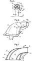
- Figure 6 is an enlarged view of another breather outlet according to the present invention mounted on the nacelle shown in figure 1, and
- Figure 7 is a cross-sectional view through the breather outlet shown in figure 6.
-
- A gas
turbine engine nacelle 10, shown in figure 1, contains a propulsive gas turbine engine suspended from an aircraft (not shown) by means of amounting pylon 12. The gas turbine engine within thenacelle 10 is provided with a gearbox having a breather, the outlet of the breather outlet is indicated at 14. Thebreather outlet 14 is shown more clearly in figures 2 and 3. - The
breather outlet 14, as shown in figures 2 and 3, extends through anapertured seal plate 16 provided on the surface of thenacelle 10. A portion of thebreather outlet 14 is within thenacelle 10 comprises atransition piece connector 17 which facilitates an interconnection between thebreather outlet 14 and the interior of the previously mentioned gearbox. - A portion of the
breather outlet 14 outside thenacelle 10 comprises anaerodynamic mast 18. Themast 18 contains abreather duct 20 which interconnects with the gearbox interior at one end and with anexhaust outlet 22 at the other end. Theexhaust outlet 22 is positioned in themast 18 so that it is generally rearwardly, or downstream, facing with respect to the operational air flow over thenacelle 10. Theexhaust outlet 22 is positioned so that it is spaced apart from the surface of thenacelle 10 by approximately 12 cm. Theexhaust outlet 22 is angled so as to be directed slightly away from thenacelle 10. These arrangements are to decrease the possibility of oil coming into contact with thenacelle 10. - The
mast 18 hasmain body portion 25 and aportion 27 which has a circular cross-sectional configuration. Themast 18 has a leadingedge 24, with respect to the operational flow of air thereover, which is curved in a convex manner. Specifically the leadingedge 24 extends from the mostupstream part 23 to theexhaust outlet 22. Themast 18 has atrailing edge 26 which is also curved in a convex manner. Thetrailing edge 26 extends from the mostdownstream part 25 of themast 18, which interconnects with thenacelle 10, to thepoint 40 of intersection with theportion 27 of themast 14. Themain body portion 25 of themast 18 has an aerodynamic profile from the leadingedge 24 to thetrailing edge 26. These configurations of the leading andtrailing edges breather outlet 14 thereby reducing its drag. - The
breather duct 20 is arranged so that it's cross-sectional configuration changes from a slot shape at it's exit from thenacelle 10 to a circular cross-sectional configuration at theexhaust outlet 22. - The
breather duct 20 is provided with a plurality of, six in this example,guide vanes 28 which extend radially across thebreather duct 20 in theportion 27 of thebreather duct 20 which has a circular cross-sectional shape. Figures 2 and 3 show theguide vanes 28 provided immediately upstream of theexhaust outlet 22. It is preferable that the axial length of the guide vanes 28 is approximately two to three times the radius of theexhaust outlet 22, more preferably 2.25 to 2.5 times the radius of theexhaust outlet 22. The guide vanes 28 extend substantially the full length of theportion 27 and thus theportion 27 is also at least 2 times the length of the radius of theexhaust outlet 22. The guide vanes 28 are flow straighteners. - The
portion 27 of themast 14 extends in a rearward, or downstream, direction from themain portion 25 of themast 14 such that theexhaust outlet 22 is spaced apart from the trailingedge 26 of themain portion 25 of themast 14. Preferably theexhaust outlet 22 is spaced approximately twice the radius of theexhaust outlet 22 from the trailingedge 26 of themain body portion 25 of themast 14, a spacing of more than twice the radius of the exhaust outlet does not give any significant improvement. - The
mast 18 has a plurality of, two in this example,vortex generators 30 which extend from themast 18 in the region of theportion 27 of thebreather duct 20 having a circular cross-sectional shape. Thevortex generators 30 have aleading edge 32, a trailingedge 34 and anattachment edge 36. Thevortex generators 30 are secured to theportion 27 of themast 18 along their attachment edges 36 by welding or other suitable means. - The leading
edge 32 is preferably a parabolic line, but other suitable lines may be used, for example an elliptical line or a straight line. It is preferable that the length of the trailingedge 34 is 1.0 to 1.5 times the radius of theexhaust outlet 22 and that the length of theattachment edge 36 is 2.0 to 3.5 times the radius of theexhaust outlet 22, preferably 3.0 times the radius of theexhaust outlet 22. It is preferred that there are two vortex generators. - It is preferable that the
point 38 of intersection of the leadingedge 32 andattachment edge 36 of thevortex generators 30 is at substantially the same distance from thenacelle 10 as thenearest point 42 of theexhaust outlet 22 to thenacelle 10. Thepoint 38 may be up to a few millimetres nearer to the nacelle than thepoint 42. The attachment edges 36 of thevortex generators 30 are arranged at an angle of approximately 14° relative to the surface of thenacelle 10 which is substantially parallel to the airflow over themast 14. The trailingedges 34 of thevortex generators 30 are spaced apart from theexhaust outlet 22 by a distance of approximately the radius of theexhaust outlet 22. - The attachment edges 36 of the
vortex generators 30 are arranged substantially either side of themast 18 and are substantially coplanar and thevortex generators 30 extend from themast 18 such that they are also arranged in the same plane. The attachment edges 36 of thevortex generators 30 are arranged at an angle B, where B is approximately 120° and the angle B is bisected by a radius C from the gas turbine engine. - In one example of a breather outlet according to the present invention, for large gas turbine engines, the
exhaust outlet 22 of thebreather duct 20 has a radius of 25mm, the trailingedge 34 of thevortex generators 30 has a length of 32mm, theattachment edge 36 of thevortex generator 30 has a length of 86mm, the trailingedge 34 is 25mm upstream of theexhaust outlet 22, theguide vanes 28 have a length of 63mm and theexhaust outlet 22 is 50mm from the trailingedge 26 of themain body portion 25 of themast 14. Thepoint 40 is approximately 12cm from thenacelle 10 and thepoint 38 is approximately 12cm from thenacelle 10. - In another example of a breather outlet according to the present invention, for a small gas turbine engines, the
exhaust outlet 22 of thebreather duct 20 has a radius of 12.5mm, the trailingedge 34 of thevortex generators 30 has a length of 12.5mm, theattachment edge 36 of thevortex generator 30 has a length of 37.5mm, the trailingedge 34 is 12.5mm upstream of theexhaust outlet 22, theguide vanes 28 have a length of 37.5mm and theexhaust outlet 22 is 25mm from the trailingedge 26 of themain body portion 25 of themast 14. - During operation of the gas turbine engine mounted within the
nacelle 10, oil is expelled in small quantities from the engine gearbox into thebreather duct 20. The oil and the air in which it is suspended flows through thebreather duct 20 to be finally exhausted in a generally downstream direction through theexhaust outlet 22. - The oil and air mixture flows through the
guide vanes 28 in theportion 27 of themast 14 before being exhausted through theexhaust outlet 22. The guide vanes 28 remove the swirl present in the air flow through theoutlet duct 20 before the oil and air mixture is discharged from theexhaust outlet 22. - The
portion 27 of themast 14 projects downstream from the main portion of themast 14 and thus theexhaust outlet 22 discharges the oil and air mixture into the airflow over themast 14 further from the turbulent region just downstream of the trailingedge 26 of themain body portion 25 of themast 14. This allows the oil and air mixture time to become steady before it is introduced into the airflow over themast 14. The provision of the space between theexhaust outlet 22 and the trailingedge 25 is the feature giving the most significant effect. - The
vortex generators 30 generate vortices in the airflow over themast 14 and these vortices act as a barrier between the oil and mixture discharged from theexhaust outlet 22 and the turbulent flow downstream of themain body portion 25 of themast 14. The vortices re-energise the turbulent flow and reduce boundary layer separation around theexhaust outlet 22 and thus minimise the possibility of the oil and air mixture being drawn towards thenacelle 10. Thus the vortices tend to cause the oil and air mixture to flow away from the surface of thenacelle 10. - The
mast 18 of thebreather outlet 14 described with reference to figures 2 to 5 comprises a single skin mast, i.e. themain body portion 25 andportion 27 are formed from a single skin of metal. - A
further breather outlet 44 as shown in figure 6 and 7 is substantially the same as thebreather outlet 14 in figures 2 to 5, however, themast 18 comprises anouter skin 46 and aninner skin 48 within theouter skin 46. In that case theinner skin 48 would define theoutlet duct 20 and this would reduce the amount of swirl in the oil and air mixture before it was discharged from theexhaust outlet 22. It may be possible to dispense with the guide vanes in theportion 27 of themast 18, alternatively they may be retained. - The
breather outlet 14 may be positioned at any angular position on thenacelle 10 and not just at the position shown, for example it is preferable to position the breather outlet at the bottom dead centre of thenacelle 10. - The mast may be manufactured from any suitable material, for example sheet metal, fibre reinforced composite material e.g. sheet steel or graphite reinforced plastic.
Claims (27)
- A breather outlet (14) suitable for use with the gearbox of an aircraft mounted gas turbine engine enclosed within a nacelle (10), the breather outlet (14) comprising a mast (18) containing a breather duct (20), the mast (18) being adapted to be located on the exterior of the nacelle (10), the breather duct (20) being operationally interconnected with the interior of the gearbox, the mast (18) comprising a main portion (25) and a sub portion (27) extending generally rearwardly from the main portion (25), the main portion (25) of the mast (18) being generally aerodynamically shaped between a leading edge (24) and a trailing edge (26), the sub portion (27) of the mast (18) having an exhaust outlet (22) for the breather duct (20), the exhaust outlet (22) being generally rearwardly facing with respect to the operational flow of air over the mast (18) and positioned so as to be spaced apart from the nacelle (10), characterised in that the exhaust outlet (22) being spaced from the trailing edge (26) of the main portion (25) of the mast (18), and the mast (18) having vortex generators (30) spaced from the exhaust outlet (22) to generate vortices in the operational flow of air over the mast (18) to act as a barrier between the airflow through the exhaust outlet (22) and the wake from the mast (18).
- A breather outlet as claimed in claim 1 wherein there are two vortex generators (30), each vortex generator (30) has a leading edge (32), a trailing edge (34) and an attachment edge (26) for securing the vortex generator (30) to the mast (18).
- A breather outlet as claimed in claim 2 wherein the vortex generators (30) are arranged at an angle of 14° to the nacelle (10).
- A breather outlet as claimed in claim 2 or claim 3 wherein the point of intersection (38) of the leading edge (32) and attachment edge (36) of the vortex generators (30) is at substantially the same distance from the nacelle (10) as the nearest point (42) of the exhaust outlet (22) to the nacelle (10).
- A breather outlet as claimed in any of claims 2 to 4 wherein the attachment edges (36) of the vortex generators (30) are arranged substantially either side of the mast (18) and are substantially coplanar and the vortex generators (30) extend from the mast (18) such that the vortex generators (30) are arranged substantially in the same plane.
- A breather outlet as claimed in claim 5 wherein the attachment edges (36) of the vortex generators (30) are approximately 120° apart.
- A breather outlet as claimed in any of claims 1 to 6 wherein the exhaust outlet (22) is arranged at an angle to direct the airflow away from the nacelle (10).
- A breather outlet as claimed in any of claims 1 to 7 wherein the breather duct (20) has means (28) to remove the swirl present in the operational airflow through the breather duct (20).
- A breather outlet as claimed in claim 8 wherein the means (28) to remove the swirl is located in the breather duct (20) in the sub portion (27) of the mast (18).
- A breather outlet as claimed in claim 9 wherein the means (28) to remove the swirl is located at the exhaust outlet (22).
- A breather outlet as claimed in claim 10 wherein the means (28) to remove the swirl comprises a plurality of vanes extending across the breather duct (20) in the sub portion (27) of the mast (18).
- A breather outlet as claimed in any of claims 9 to 11 wherein the sub portion (27) has a circular cross-section.
- A breather outlet as claimed in claim 12 wherein the axial length of the vanes (28) is two to three times the radius of the sub portion (27) of the mast (18).
- A breather outlet as claimed in claim 12 or claim 13 wherein there are six vanes (28).
- A breather outlet as claimed in any of claims 12 to 14 wherein the trailing edges (34) of the vortex generators (30) are spaced a distance from the exhaust outlet (22) substantially the same as the radius of the exhaust outlet (22).
- A breather outlet as claimed in any of claims 12 to 15 wherein the trailing edges (34) of the vortex generators (30) extend from the mast (18) by a length of 1 to 1.5 times the radius of the exhaust outlet (22).
- A breather outlet as claimed in any of claims 12 to 16 wherein the attachment edges (36) of the vortex generators (30) have a length of 2.0 to 3.5 times the radius of the exhaust outlet (22).
- A breather outlet as claimed in claim 12 wherein the exhaust outlet (22) has a radius of 25mm, the vanes (28) have a length of 50 to 75 mm, the trailing edges (34) of the vortex generators (30) are spaced 25mm from the exhaust outlet (22), the trailing edges (34) of the vortex generators (30) extend 32mm from the mast (18), the attachment edges (36) of the vortex generators (30) have a length of 86mm, the exhaust outlet (22) is spaced at least 50mm from the main portion (25) of the mast (18), the point of intersection (38) of the leading edge (32) of the vortex generator (30) and the attachment edge (36) of the vortex generator (30) is substantially 12cm from the nacelle (10) and the nearest point (42) of the exhaust outlet (22) is substantially 12cm from the nacelle (10).
- A breather outlet as claimed in any of claims 1 to 18 wherein each vortex generator (30) has a parabolic leading edge (32).
- A breather outlet (14) suitable for use with the gearbox of an aircraft mounted gas turbine engine enclosed within a nacelle (10), the breather outlet (14) comprising a mast (18) containing a breather duct (20), the mast (18) being adapted to be located on the exterior of the nacelle (10), the breather duct (20) being operationally interconnected with the interior of the gearbox, the mast (18) comprising a main portion (25) and a sub portion (27) extending generally rearwardly from the main portion (25), the main portion of (25) of the mast (18) being generally aerodynamically shaped between a leading edge (24) and a trailing edge (26), the sub portion (27) of the mast (18) having an exhaust outlet (22) for the breather duct (20), the exhaust outlet (22) being generally rearwardly facing with respect to the operational flow of air over the mast (18) and positioned so as to be spaced apart from the nacelle (10), characterised in that the exhaust outlet (22) being spaced from the trailing edge (26) of the main portion (25) of the mast (18), and the breather duct (20) has means (28) to remove the swirl present in the operational air flow through the breather duct (20).
- A breather outlet as claimed in claim 20 wherein the means (28) to remove the swirl is located in the breather duct (20) in the sub portion (27) of the mast (18).
- A breather outlet as claimed in claim 21 wherein the means (28) to remove the swirl is located at the exhaust outlet (22).
- A breather outlet as claimed in claim 22 wherein the means (28) to remove the swirl comprises a plurality of vanes extending across the breather duct (20) in the sub portion (27) of the mast.
- A breather outlet as claimed in any of claims 20 to 23 wherein the sub portion (27) has a circular cross-section.
- A breather outlet as claimed in claim 24 wherein the axial length of the vanes (28) is two to three times the radius of the sub portion (27) of the mast (18).
- A breather outlet as claimed in claim 24 or claim 25 wherein there are six vanes (28).
- A gas turbine engine comprising a breather outlet as claimed in any of claims 1 to 26.
Applications Claiming Priority (2)
| Application Number | Priority Date | Filing Date | Title |
|---|---|---|---|
| GBGB9804807.7A GB9804807D0 (en) | 1998-03-06 | 1998-03-06 | A breather outlet |
| GB9804807 | 1998-03-06 |
Publications (3)
| Publication Number | Publication Date |
|---|---|
| EP0940338A2 true EP0940338A2 (en) | 1999-09-08 |
| EP0940338A3 EP0940338A3 (en) | 2002-03-13 |
| EP0940338B1 EP0940338B1 (en) | 2003-04-23 |
Family
ID=10828122
Family Applications (1)
| Application Number | Title | Priority Date | Filing Date |
|---|---|---|---|
| EP99300890A Expired - Lifetime EP0940338B1 (en) | 1998-03-06 | 1999-02-08 | Gearbox breather outlet |
Country Status (4)
| Country | Link |
|---|---|
| US (1) | US6116015A (en) |
| EP (1) | EP0940338B1 (en) |
| DE (1) | DE69907054T2 (en) |
| GB (1) | GB9804807D0 (en) |
Cited By (11)
| Publication number | Priority date | Publication date | Assignee | Title |
|---|---|---|---|---|
| GB2374026A (en) * | 2001-04-07 | 2002-10-09 | Rolls Royce Plc | Breather outlet for evaporating excess oil by electromagnetic radiation |
| GB2376269A (en) * | 2001-06-08 | 2002-12-11 | Rolls Royce Plc | A gas turbine engine breather outlet |
| EP2065303A2 (en) * | 2007-11-28 | 2009-06-03 | United Technologies Corporation | Combined gearbox breather and drain mast for a jet aircraft engine |
| EP2253538A3 (en) * | 2009-05-19 | 2011-04-13 | Rolls-Royce plc | A gas turbine engine having a nacelle and a breather duct |
| EP2316725A1 (en) * | 2009-11-02 | 2011-05-04 | Rolls-Royce plc | Breather duct shielding |
| US8348199B2 (en) | 2009-11-02 | 2013-01-08 | Rolls-Royce, Plc | Boundary layer energiser |
| EP2620361A1 (en) * | 2012-01-26 | 2013-07-31 | Airbus Operations, S.L. | Drainage mast of the compartment of the auxiliary power unit of an aircraft |
| US8967964B2 (en) | 2009-11-02 | 2015-03-03 | Rolls-Royce Plc | Boundary layer energiser |
| EP2853482A1 (en) * | 2013-09-18 | 2015-04-01 | Goodrich Corporation | Drain mast |
| US10895201B2 (en) | 2016-05-02 | 2021-01-19 | Rolls-Royce Deutschland Ltd & Co Kg | Turbofan engine and a method for exhausting breather air of an oil separator in a turbofan engine |
| EP4424589A1 (en) * | 2023-02-28 | 2024-09-04 | Airbus Operations GmbH | Aircraft drain mast |
Families Citing this family (7)
| Publication number | Priority date | Publication date | Assignee | Title |
|---|---|---|---|---|
| FR2901538B1 (en) * | 2006-05-23 | 2008-07-18 | Airbus France Sas | AIRCRAFT COMPRISING A DEVICE FOR REDUCING INDUCED TRAINING |
| US9091214B2 (en) * | 2007-06-28 | 2015-07-28 | United Technologies Corporation | Reduced gearbox size by separate electrically powered engine oil system |
| US8621839B2 (en) * | 2009-09-28 | 2014-01-07 | Pratt & Whitney Canada Corp. | Gas turbine engine breather exhaust oil collector |
| DE102009053002A1 (en) * | 2009-11-16 | 2011-05-19 | Rolls-Royce Deutschland Ltd & Co Kg | Exhaust outlet for lubricating oil system of aircraft engine, is arranged at exterior surface of engine- or engine mount lining, where region of exterior surface is limited to edge of outlet |
| US20110121137A1 (en) * | 2009-11-24 | 2011-05-26 | Electrofilm Manufacturing Company Llc | Method and apparatus for directing waste away from aircraft |
| DE102009060051A1 (en) * | 2009-12-21 | 2011-06-22 | Rolls-Royce Deutschland Ltd & Co KG, 15827 | Arrangement for blowing off from the lubricating oil ventilation system of a gas turbine engine from separate exhaust air |
| GB2494895B (en) * | 2011-09-22 | 2014-11-26 | Rolls Royce Plc | A fluid management apparatus and method |
Citations (1)
| Publication number | Priority date | Publication date | Assignee | Title |
|---|---|---|---|---|
| EP0439923B1 (en) | 1990-01-30 | 1993-06-30 | ROLLS-ROYCE plc | Gearbox breather outlet |
Family Cites Families (5)
| Publication number | Priority date | Publication date | Assignee | Title |
|---|---|---|---|---|
| US3041832A (en) * | 1959-05-12 | 1962-07-03 | Gen Motors Corp | Lubrication vent for a turbine engine |
| US4172572A (en) * | 1977-04-28 | 1979-10-30 | Pratt & Whitney Aircraft Of Canada Ltd. | Exhaust stub with end plate |
| US4466587A (en) * | 1981-12-21 | 1984-08-21 | General Electric Company | Nacelle installation |
| US4655419A (en) * | 1984-12-31 | 1987-04-07 | The Boeing Company | Vortex generator |
| US5495872A (en) * | 1994-01-31 | 1996-03-05 | Integrity Measurement Partners | Flow conditioner for more accurate measurement of fluid flow |
-
1998
- 1998-03-06 GB GBGB9804807.7A patent/GB9804807D0/en not_active Ceased
-
1999
- 1999-02-08 EP EP99300890A patent/EP0940338B1/en not_active Expired - Lifetime
- 1999-02-08 DE DE69907054T patent/DE69907054T2/en not_active Expired - Lifetime
- 1999-02-11 US US09/247,905 patent/US6116015A/en not_active Expired - Lifetime
Patent Citations (1)
| Publication number | Priority date | Publication date | Assignee | Title |
|---|---|---|---|---|
| EP0439923B1 (en) | 1990-01-30 | 1993-06-30 | ROLLS-ROYCE plc | Gearbox breather outlet |
Cited By (20)
| Publication number | Priority date | Publication date | Assignee | Title |
|---|---|---|---|---|
| US6513332B2 (en) | 2001-04-07 | 2003-02-04 | Rolls-Royce Plc | Oil/air breather outlet |
| GB2374026B (en) * | 2001-04-07 | 2004-09-29 | Rolls Royce Plc | Oil/air breather outlet |
| GB2374026A (en) * | 2001-04-07 | 2002-10-09 | Rolls Royce Plc | Breather outlet for evaporating excess oil by electromagnetic radiation |
| GB2376269A (en) * | 2001-06-08 | 2002-12-11 | Rolls Royce Plc | A gas turbine engine breather outlet |
| EP2065303A3 (en) * | 2007-11-28 | 2012-06-27 | United Technologies Corporation | Combined gearbox breather and drain mast for a jet aircraft engine |
| EP2065303A2 (en) * | 2007-11-28 | 2009-06-03 | United Technologies Corporation | Combined gearbox breather and drain mast for a jet aircraft engine |
| EP2253539A3 (en) * | 2009-05-19 | 2011-04-13 | Rolls-Royce plc | Breather duct shielding |
| EP2253538A3 (en) * | 2009-05-19 | 2011-04-13 | Rolls-Royce plc | A gas turbine engine having a nacelle and a breather duct |
| US8511056B2 (en) | 2009-05-19 | 2013-08-20 | Rolls-Royce Plc | Gas turbine engine having a nacelle and a breather duct |
| US8572984B2 (en) | 2009-05-19 | 2013-11-05 | Rolls-Royce Plc | Breather duct shielding |
| EP2316725A1 (en) * | 2009-11-02 | 2011-05-04 | Rolls-Royce plc | Breather duct shielding |
| US8967964B2 (en) | 2009-11-02 | 2015-03-03 | Rolls-Royce Plc | Boundary layer energiser |
| US8348199B2 (en) | 2009-11-02 | 2013-01-08 | Rolls-Royce, Plc | Boundary layer energiser |
| US8657569B2 (en) | 2009-11-02 | 2014-02-25 | Rolls-Royce Plc | Breather duct shielding |
| EP2620361A1 (en) * | 2012-01-26 | 2013-07-31 | Airbus Operations, S.L. | Drainage mast of the compartment of the auxiliary power unit of an aircraft |
| US9321520B2 (en) | 2012-01-26 | 2016-04-26 | Airbus Operations S.L. | Drainage mast of the compartment of the auxiliary power unit of an aircraft |
| EP2853482A1 (en) * | 2013-09-18 | 2015-04-01 | Goodrich Corporation | Drain mast |
| JP2015096410A (en) * | 2013-09-18 | 2015-05-21 | グッドリッチ コーポレイション | Drain mast |
| US10895201B2 (en) | 2016-05-02 | 2021-01-19 | Rolls-Royce Deutschland Ltd & Co Kg | Turbofan engine and a method for exhausting breather air of an oil separator in a turbofan engine |
| EP4424589A1 (en) * | 2023-02-28 | 2024-09-04 | Airbus Operations GmbH | Aircraft drain mast |
Also Published As
| Publication number | Publication date |
|---|---|
| EP0940338B1 (en) | 2003-04-23 |
| GB9804807D0 (en) | 1998-04-29 |
| DE69907054D1 (en) | 2003-05-28 |
| DE69907054T2 (en) | 2003-11-06 |
| US6116015A (en) | 2000-09-12 |
| EP0940338A3 (en) | 2002-03-13 |
Similar Documents
| Publication | Publication Date | Title |
|---|---|---|
| EP0940338B1 (en) | Gearbox breather outlet | |
| EP0241404B1 (en) | Gas turbine engine nacelle | |
| US4466587A (en) | Nacelle installation | |
| US8572984B2 (en) | Breather duct shielding | |
| CA2333695C (en) | Integral inertial particle separator for radial inlet gas turbine engine | |
| US4892269A (en) | Spinner ducted exhaust for pusher turboprop engines | |
| EP1071608B2 (en) | Biplanar scarfed nacelle inlet | |
| JP5672005B2 (en) | Aircraft leading edge and aircraft nacelle including air vents | |
| US4930725A (en) | Pusher propeller installation for turboprop engines | |
| US20070272796A1 (en) | Ducted open rotor apparatus and method | |
| EP3381792B1 (en) | Aerodynamic drainage device | |
| EP2402250A2 (en) | Pylon for attaching a gas turbine engine | |
| JPH05193587A (en) | Aircraft engine nacelle with arc contour | |
| EP0439923B1 (en) | Gearbox breather outlet | |
| GB2562433A (en) | An airplane | |
| CA3032140C (en) | Aircraft having an aft engine | |
| EP0440640A1 (en) | Spinner ducted exhaust for pusher turboprop engines | |
| GB2259114A (en) | Aircraft engine nacelle profile | |
| CN111075760A (en) | Fluid wing | |
| US8657569B2 (en) | Breather duct shielding | |
| GB2113769A (en) | Ram jet motors | |
| RU2174616C2 (en) | Intake unit for turboprop engine | |
| CN116902202A (en) | hybrid wing body aircraft |
Legal Events
| Date | Code | Title | Description |
|---|---|---|---|
| PUAI | Public reference made under article 153(3) epc to a published international application that has entered the european phase |
Free format text: ORIGINAL CODE: 0009012 |
|
| AK | Designated contracting states |
Kind code of ref document: A2 Designated state(s): AT BE CH CY DE DK ES FI FR GB GR IE IT LI LU MC NL PT SE Kind code of ref document: A2 Designated state(s): DE FR GB |
|
| AX | Request for extension of the european patent |
Free format text: AL;LT;LV;MK;RO;SI |
|
| PUAL | Search report despatched |
Free format text: ORIGINAL CODE: 0009013 |
|
| AK | Designated contracting states |
Kind code of ref document: A3 Designated state(s): AT BE CH CY DE DK ES FI FR GB GR IE IT LI LU MC NL PT SE |
|
| AX | Request for extension of the european patent |
Free format text: AL;LT;LV;MK;RO;SI |
|
| 17P | Request for examination filed |
Effective date: 20020201 |
|
| 17Q | First examination report despatched |
Effective date: 20020529 |
|
| GRAH | Despatch of communication of intention to grant a patent |
Free format text: ORIGINAL CODE: EPIDOS IGRA |
|
| AKX | Designation fees paid |
Free format text: DE FR GB |
|
| GRAH | Despatch of communication of intention to grant a patent |
Free format text: ORIGINAL CODE: EPIDOS IGRA |
|
| GRAA | (expected) grant |
Free format text: ORIGINAL CODE: 0009210 |
|
| AK | Designated contracting states |
Designated state(s): DE FR GB |
|
| REG | Reference to a national code |
Ref country code: GB Ref legal event code: FG4D |
|
| REF | Corresponds to: |
Ref document number: 69907054 Country of ref document: DE Date of ref document: 20030528 Kind code of ref document: P |
|
| REG | Reference to a national code |
Ref country code: IE Ref legal event code: FG4D |
|
| ET | Fr: translation filed | ||
| PLBE | No opposition filed within time limit |
Free format text: ORIGINAL CODE: 0009261 |
|
| STAA | Information on the status of an ep patent application or granted ep patent |
Free format text: STATUS: NO OPPOSITION FILED WITHIN TIME LIMIT |
|
| 26N | No opposition filed |
Effective date: 20040126 |
|
| REG | Reference to a national code |
Ref country code: IE Ref legal event code: MM4A |
|
| REG | Reference to a national code |
Ref country code: FR Ref legal event code: PLFP Year of fee payment: 17 |
|
| REG | Reference to a national code |
Ref country code: FR Ref legal event code: PLFP Year of fee payment: 18 |
|
| REG | Reference to a national code |
Ref country code: FR Ref legal event code: PLFP Year of fee payment: 19 |
|
| REG | Reference to a national code |
Ref country code: FR Ref legal event code: PLFP Year of fee payment: 20 |
|
| PGFP | Annual fee paid to national office [announced via postgrant information from national office to epo] |
Ref country code: DE Payment date: 20180227 Year of fee payment: 20 Ref country code: GB Payment date: 20180227 Year of fee payment: 20 |
|
| PGFP | Annual fee paid to national office [announced via postgrant information from national office to epo] |
Ref country code: FR Payment date: 20180227 Year of fee payment: 20 |
|
| REG | Reference to a national code |
Ref country code: DE Ref legal event code: R071 Ref document number: 69907054 Country of ref document: DE |
|
| REG | Reference to a national code |
Ref country code: GB Ref legal event code: PE20 Expiry date: 20190207 |
|
| PG25 | Lapsed in a contracting state [announced via postgrant information from national office to epo] |
Ref country code: GB Free format text: LAPSE BECAUSE OF EXPIRATION OF PROTECTION Effective date: 20190207 |