EP1031218B1 - Zeitvariante trelliskodierte phasensprungmodulation - Google Patents
Zeitvariante trelliskodierte phasensprungmodulation Download PDFInfo
- Publication number
- EP1031218B1 EP1031218B1 EP98953927A EP98953927A EP1031218B1 EP 1031218 B1 EP1031218 B1 EP 1031218B1 EP 98953927 A EP98953927 A EP 98953927A EP 98953927 A EP98953927 A EP 98953927A EP 1031218 B1 EP1031218 B1 EP 1031218B1
- Authority
- EP
- European Patent Office
- Prior art keywords
- encoder
- trellis
- output
- puncture
- bits
- Prior art date
- Legal status (The legal status is an assumption and is not a legal conclusion. Google has not performed a legal analysis and makes no representation as to the accuracy of the status listed.)
- Expired - Lifetime
Links
- 239000000872 buffer Substances 0.000 claims description 17
- 238000013507 mapping Methods 0.000 claims description 11
- 238000000034 method Methods 0.000 description 38
- 238000004891 communication Methods 0.000 description 11
- 238000010586 diagram Methods 0.000 description 8
- 230000004931 aggregating effect Effects 0.000 description 7
- 230000000875 corresponding effect Effects 0.000 description 7
- 230000008569 process Effects 0.000 description 5
- 238000000638 solvent extraction Methods 0.000 description 5
- 230000005540 biological transmission Effects 0.000 description 4
- 238000012217 deletion Methods 0.000 description 4
- 230000037430 deletion Effects 0.000 description 4
- 230000000737 periodic effect Effects 0.000 description 3
- 230000002776 aggregation Effects 0.000 description 2
- 238000004220 aggregation Methods 0.000 description 2
- 230000036039 immunity Effects 0.000 description 2
- 238000005192 partition Methods 0.000 description 2
- 230000007704 transition Effects 0.000 description 2
- 238000007476 Maximum Likelihood Methods 0.000 description 1
- 230000003213 activating effect Effects 0.000 description 1
- 229910002056 binary alloy Inorganic materials 0.000 description 1
- 230000000052 comparative effect Effects 0.000 description 1
- 230000000295 complement effect Effects 0.000 description 1
- 230000002079 cooperative effect Effects 0.000 description 1
- 238000012937 correction Methods 0.000 description 1
- 238000013461 design Methods 0.000 description 1
- 238000001514 detection method Methods 0.000 description 1
- 230000006872 improvement Effects 0.000 description 1
- 238000003780 insertion Methods 0.000 description 1
- 230000037431 insertion Effects 0.000 description 1
- 238000004519 manufacturing process Methods 0.000 description 1
- 238000012545 processing Methods 0.000 description 1
Images


Classifications
-
- H—ELECTRICITY
- H04—ELECTRIC COMMUNICATION TECHNIQUE
- H04L—TRANSMISSION OF DIGITAL INFORMATION, e.g. TELEGRAPHIC COMMUNICATION
- H04L1/00—Arrangements for detecting or preventing errors in the information received
- H04L1/004—Arrangements for detecting or preventing errors in the information received by using forward error control
- H04L1/0056—Systems characterized by the type of code used
- H04L1/0059—Convolutional codes
-
- H—ELECTRICITY
- H04—ELECTRIC COMMUNICATION TECHNIQUE
- H04L—TRANSMISSION OF DIGITAL INFORMATION, e.g. TELEGRAPHIC COMMUNICATION
- H04L1/00—Arrangements for detecting or preventing errors in the information received
- H04L1/004—Arrangements for detecting or preventing errors in the information received by using forward error control
- H04L1/0045—Arrangements at the receiver end
- H04L1/0054—Maximum-likelihood or sequential decoding, e.g. Viterbi, Fano, ZJ algorithms
-
- H—ELECTRICITY
- H04—ELECTRIC COMMUNICATION TECHNIQUE
- H04L—TRANSMISSION OF DIGITAL INFORMATION, e.g. TELEGRAPHIC COMMUNICATION
- H04L27/00—Modulated-carrier systems
- H04L27/18—Phase-modulated carrier systems, i.e. using phase-shift keying
- H04L27/186—Phase-modulated carrier systems, i.e. using phase-shift keying in which the information is carried by both the individual signal points and the subset to which the individual signal points belong, e.g. coset coding or related schemes
Definitions
- the present invention relates generally to a method for data transmission employing trellis coded modulation, and, more particularly, to a coded modulation scheme implementing time-varying trellis codes.
- Trellis coded modulation is a technique for combining coding and modulation to increase channel capacity and improve bit error performance.
- This coded modulation scheme is based on the concept of mapping by set partitioning described by Ungerboeck in the seminal paper Channel Coding With MultilevellPhase Signals, IEEE Transactions on Information Theory, VoL IT-28, No. 1, Jan. 1982 .
- Trellis coded modulation (TCM) combines coding and modulation operations, thus allowing for improved reliability of the communications system without increasing power or bandwidth requirements.
- a typical TCM scheme involves the mapping of an encoder output directly to a point on a signal constellation, such as an 8-PSK constellation.
- the combination of the encoding and mapping elements is jointly optimized so as to obtain good error performance.
- an encoder could take two bits as input and have a three-bit output which is mapped to an 8-PSK constellation. In such a case, the encoder would be said to encode at a 2/3 rate, that is, two inputs bits produce three encoded output bits. Since each point in the signal constellation may have one of two poosible values in a binary system, it is necessary to have the number of encoded output bits equal to the logarithm base 2 of the number of points in the desired signal constellation.
- each branch of the trellis corresponds to one 8-PSK symbol, which facilitates soft decision decoding.
- an apparatus for encoding an input data stream comprising: a convolutional encoder for coding said input data stream at a first selected code rate to generate an intermediate coded output; and a puncture buffer for puncturing said intermediate coded output to generate a final coded output, and characterized in that the puncture buffer is configured to vary the puncture period and puncture pattern periodically while the total number of output bits generated during any given puncture period remains constant.
- the present invention relates to a trellis coded modulation scheme which allows the encoder output to be mapped directly to a signal constellation previously thought to be incompatible. For example, using the present invention, the output of a 3/4 rate encoder can be mapped directly onto an 8 point signal constellation where in the past it was thought that a 16 point constellation was needed. This result is accomplished by use of a time-varying trellis code.
- a time-varying trellis code is obtained by using a variable rate encoder which produces at its output the correct number of bits to map directly onto the desired signal constellation.
- the variable rate encoder could obtain coding rates of 2/3 and 3/3 at different time intervals.
- a rate 3/4 code can be obtained by coding the first 6 input bits at rate 2/3 and the final 3 input bits at rate 3/3.
- the first 6 input bits represent three trellis stages and the final 3 input bits represent a fourth trellis stage. Over all four trellis stages there are a total of 9 input bits and 12 output bits giving an effective rate of 3/4. However, only 3 output bits are generated at each stage which can be mapped directly onto an 8 point signal constellation.
- the method of implementing the time-varying trellis code of the present invention is to puncture the output of a single convolutional encoder using two distinct puncture patterns. At pre-determined instants, the puncturing pattern is switched thereby realizing two different coding rates.
- the resulting trellis time-varying By aggregating the trellis stages of the convolutional encoder together with different levels of aggregation, the resulting trellis time-varying. For example, if the trellis of the convolutional encoder has two branches per state, the first puncturing pattern could be over two trellis stages, and the second puncturing pattern could be over three trellis stages. Aggregating two and three trellis stages, we get a time-varying trellis with four branches and eight branches respectively.
- FIG. 1 illustrates a digital communications system, generally indicated by the numeral 10, employing a trellis coded modulation scheme.
- the system 10 consists generally of a transmitter 14 and a receiver 30 which are coupled by a communications channel 12.
- the transmitter 14 includes an information source 16, a source encoder 18, a channel coder 20 and a modulator 22.
- the information source 16 provides the source data stream that is to be ultimately conveyed to the receiver 30.
- This source data is assumed to be in a digitized format and is passed directly to the source encoder 18.
- the source encoder 18 removes redundancy or randomizes the source data stream, producing an information sequence which has been optimized for maximum information content.
- the information sequence from the source encoder 18 is passed to the channel coder 20.
- the channel encoder 20 is designed so as to introduce an element of redundancy into the information sequence which is supplied by the source encoder 18 to generate a coded output. While initially appearing at odds with the function of the source encoder 18 previously discussed, in reality the redundancy added by the channel coder 20 serves to enhance the error correction capability of the communication system. By introducing redundant information into the information sequence in a controlled manner, a receiver having knowledge of the codes used can detect and possibly correct errors which may occur during transmission by making use of the redundant information.
- the modulator 22 interfaces the channel coder 20 to the communications channel 12. That is, the modulator 22 receives coded output from the channel coder 20 and generates waveforms that both suit the physical nature of the channel 12 and can be efficiently transmitted over the channel 12.
- the term "signal constellation” is often used to refer to the set of possible signal waveforms available for mapping of the coded output of the channel coder 20. These output waveforms, or signal constellation schemes, are generally selected with regard to either simplification of the communication system, optimal detection performance, power requirements, or bandwidth availability. Typical signal constellations used in digital communications system modulation include 16QAM, 8-PSK, 4-PSK and the like.
- a demodulator 32 processes the output waveform (which is corrupted by the channel 12 during transmission) at any given time to determine which of the possible signals in the signal constellation was transmitted. For example, when binary modulation is used, the demodulator 32 processes the received waveform and decides whether a transmitted bit is a 0 or 1. When the transmitted sequence includes redundancy introduced by channel coding, the output of the demodulator 32 is passed to a decoder 34 which attempts to reconstruct the original information sequence from it's a priori knowledge of the code used by the channel coder 16. A measure of how well the demodulator 32 and decoder 34 perform is the frequency with which errors occur in the decoded sequence.
- a source decoder 36 accepts the output sequence from the decoder 34, and from knowledge of the source encoding method, attempts to reconstruct the original signal from the source 14.
- the difference between the reconstructed signal and the original is a measure of the distortion introduced by the communication system.
- the trellis coder 50 comprises a convolutional encoder 52 and a signal mapper 60.
- the convolutional encoder 52 implements specific error control codes for formatting the data to be transmitted in such a manner so as to increase its immunity to noise.
- the convolutional encoder 52 receives the information sequence provided by the source encoder 16 and generates a coded output which possesses a high degree of noise immunity. This coded output is then passed to the signal mapper 60 which in turn maps the coded output bits to points in an appropriate signal constellation.
- the mapping scheme is chosen so that the Euclidean distance between transmitted sequences is maximized.
- the method of the present invention involves an improvement of the trellis coded modulation system described above.
- the convolutional encoder 52 typically adds an element of controlled redundancy to the information sequence via the insertion of error control bits. Consequently, the number of coded output bits from the convolutional encoder 52 is greater than the number of bits in the information sequence.
- the coding rate is defined as the ratio of bits in the information sequence to the number of coded output bits. The number of coded output bits determines the size of the signal constellation required of the modulator or mapper.
- the present invention solves this problem by utilizing a time-varying trellis code.
- the desired code rate is obtained by using a combination of encoders which are switched periodically. Each encoder has a code rate that produces the correct number of coded output bits to map directly onto a selected signal constellation. By alternating between encoders at different coding intervals, it is possible to achieve coding rates that otherwise would not be practical using the selected signal constellation.
- a rate 3/4 code can be implemented using the coding method of the present invention and mapped directly onto an 8-PSK signal constellation.
- a rate 2/3 encoder and a rate 3/3 encoder are employed at different intervals of time. Two input bits are presented to the rate 2/3 encoder during three consecutive coding intervals. Consequently, a total of six input bits are processed, resulting in the production of nine coded output bits.
- the next three input bits are provided to the rate 3/3 encoder, which produces three coded output bits.
- at each coding interval only three coded output bits were generated which can be mapped directly to the 8-PSK signal constellation.
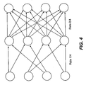
- the coding method of the present invention results in a time-varying trellis code which is illustrated in Figure 4 .
- a trellis structure is shown representing a time-varying trellis code which alternates between a rate 1/4 code and a rate 2/4 code at every coding interval.
- Each column represents a coding interval or stage and each circle represents a particular state.
- the branches of the trellis structure represent transitions between states in two adjacent coding intervals.
- a path is a series of connected branches that extend through the trellis structure.
- a rate 1/4 code there are two branches per state in the trellis structure.
- a rate 2/4 there are four branches per state in the trellis structure. Every path through the trellis structure corresponds to a unique sequence of valid code words generated by the encoder.
- the encoding method There are a number of possible ways, described below, to implement the encoding method. Three methods are described and will be referred to as a multiple encoder method not in accordance with the invention, a puncture method according to the present invention, and a look-up table method not in accordance with the invention.
- the multiple encoder method the input data stream or information sequence is switched between multiple encoders having different coding rates.
- different coding rates are realized by applying different puncture patterns to the output of a single encoder.
- the multiple encoders are implemented as a look-up tables in a memory device. A processor "looks-up" the appropriate output and state transition given the input and the current state.
- Figure 5 illustrates the multiple encoder arrangement of the enhanced trellis coded modulation scheme described above.
- a trellis coder 70 is comprised of a pair of encoders 72 and 74, an input controller 84, and an output controller 86.
- Encoders 72 and 74 are implemented in the form of shift registers 76, 78 and combinational nodes 80, 82 as shown in Figure 6 .
- Encoder 72 includes two shift registers 76 and four combinational nodes 80. The two shift registers 76 have a total of six delay cells.
- Encoder 72 receives two source encoded input bits and produces four convolutionally encoded output bits, thus establishing a coding rate of 2/4.
Landscapes
- Engineering & Computer Science (AREA)
- Computer Networks & Wireless Communication (AREA)
- Signal Processing (AREA)
- Artificial Intelligence (AREA)
- Error Detection And Correction (AREA)
- Digital Transmission Methods That Use Modulated Carrier Waves (AREA)
- Detection And Prevention Of Errors In Transmission (AREA)
Claims (2)
- Vorrichtung zum Codieren eines Eingangsdatenstroms, umfassend:einen Faltungs-Codierer (92) zum Codieren des Eingangsdatenstroms bei einer ersten ausgewählten Coderate zum Erzeugen einer zwischencodierten Ausgabe; und einen Punktierungspuffer (94) zum Punktieren der zwischencodierten Ausgabe zum Erzeugen einer final codierten Ausgabe, und dadurch gekennzeichnet, dass der Punktierungspuffer konfiguriert ist, um die Punktierungsperiode und das Punktierungsmuster periodisch zu variieren während die Gesamtzahl der während irgendeiner gegebenen Punktierungsperiode erzeugten Ausgangsbits konstant bleibt.
- Codiervorrichtung nach Anspruch 1, ferner eine Abbildungseinrichtung (60) einschließend zum Abbilden der codierten Ausgabe der Punktierungsstufe auf eine Signalkonstellation.
Applications Claiming Priority (3)
| Application Number | Priority Date | Filing Date | Title |
|---|---|---|---|
| US08/963,482 US6131180A (en) | 1997-11-03 | 1997-11-03 | Trellis coded modulation system |
| US963482 | 1997-11-03 | ||
| PCT/US1998/022470 WO1999023798A1 (en) | 1997-11-03 | 1998-10-22 | Time-varying trellis coded psk |
Publications (2)
| Publication Number | Publication Date |
|---|---|
| EP1031218A1 EP1031218A1 (de) | 2000-08-30 |
| EP1031218B1 true EP1031218B1 (de) | 2008-09-03 |
Family
ID=25507304
Family Applications (1)
| Application Number | Title | Priority Date | Filing Date |
|---|---|---|---|
| EP98953927A Expired - Lifetime EP1031218B1 (de) | 1997-11-03 | 1998-10-22 | Zeitvariante trelliskodierte phasensprungmodulation |
Country Status (7)
| Country | Link |
|---|---|
| US (1) | US6131180A (de) |
| EP (1) | EP1031218B1 (de) |
| JP (1) | JP4094809B2 (de) |
| AU (1) | AU1117699A (de) |
| CA (1) | CA2308194A1 (de) |
| DE (1) | DE69839968D1 (de) |
| WO (1) | WO1999023798A1 (de) |
Families Citing this family (26)
| Publication number | Priority date | Publication date | Assignee | Title |
|---|---|---|---|---|
| AU2848699A (en) * | 1998-03-30 | 1999-10-18 | Northern Telecom Limited | Adaptive modulation for cdma systems |
| US6738949B2 (en) * | 1998-05-13 | 2004-05-18 | Matsushita Electric Industrial Co., Ltd. | Error correction circuit and error correction method |
| JP2000004215A (ja) * | 1998-06-16 | 2000-01-07 | Matsushita Electric Ind Co Ltd | 送受信システム |
| JP2000068862A (ja) | 1998-08-19 | 2000-03-03 | Fujitsu Ltd | 誤り訂正符号化装置 |
| US6247158B1 (en) * | 1998-11-30 | 2001-06-12 | Itt Manufacturing Enterprises, Inc. | Digital broadcasting system and method |
| US6421395B1 (en) * | 1999-02-09 | 2002-07-16 | Lucent Technologies Inc. | Termination of coded or uncoded modulation with path-oriented decoder |
| IL141800A0 (en) | 1999-07-06 | 2002-03-10 | Samsung Electronics Co Ltd | Rate matching device and method for a data communication system |
| US7054377B1 (en) * | 1999-12-15 | 2006-05-30 | Paradyne Corporation | Space diversity trellis interleaver system and method |
| KR100374037B1 (ko) * | 2000-04-21 | 2003-02-26 | 삼성전자주식회사 | 데이터 통신시스템의 가변 데이터전송율 정합 방법 및 장치 |
| KR100865789B1 (ko) * | 2000-07-01 | 2008-10-29 | 엔엑스티웨이브 코뮤니케이션즈 인크 | 8vsb 신호를 위한 로버스트 데이터 확장 |
| US7437654B2 (en) * | 2000-11-29 | 2008-10-14 | Lucent Technologies Inc. | Sub-packet adaptation in a wireless communication system |
| US20040028076A1 (en) * | 2001-06-30 | 2004-02-12 | Strolle Christopher H | Robust data extension for 8vsb signaling |
| KR20030049302A (ko) * | 2001-12-14 | 2003-06-25 | 한국전자통신연구원 | 디지털 방송 시스템에서의 기저대역 부호화 장치 및 그를이용한 주파수 변조 방법 |
| DE10202090B4 (de) * | 2002-01-21 | 2010-08-12 | Infineon Technologies Ag | Elektronische Sender-Empfänger-Vorrichtung |
| US8151175B2 (en) * | 2002-04-05 | 2012-04-03 | Sentel Corporation | Fault tolerant decoding method and apparatus |
| US7657822B2 (en) * | 2002-05-31 | 2010-02-02 | Broadcom Corporation | True bit level decoding of TTCM (turbo trellis code modulation) of variable rates and signal constellations |
| AU2003259967A1 (en) * | 2002-08-20 | 2004-03-11 | Globespanvirata Incorporated | Method and apparatus for generating a 64 state 4-d trellis code in dmt |
| US7391834B2 (en) * | 2002-10-01 | 2008-06-24 | Intel Corporation | Pulse amplitude modulated system with reduced intersymbol interference |
| US7415075B2 (en) * | 2002-10-29 | 2008-08-19 | Conexant Systems, Inc. | Multi-rate encoding and decoding system |
| SG124272A1 (en) * | 2004-02-26 | 2006-08-30 | Oki Techno Ct Singapore Pte | A modulation/demodulation apparatus for the encoding and decoding of data and a method for encoding and decoding data |
| US7953047B2 (en) * | 2005-01-24 | 2011-05-31 | Qualcomm Incorporated | Parser for multiple data streams in a communication system |
| US8363738B2 (en) | 2005-12-05 | 2013-01-29 | Qualcomm Incorporated | Hierarchical coding for multicast messages |
| US8102923B2 (en) | 2005-12-05 | 2012-01-24 | Qualcomm Incorporated | Hierarchical coding for multicast messages |
| US7639751B2 (en) * | 2006-04-04 | 2009-12-29 | Samsung Electronics Co., Ltd. | Advanced-VSB system (A-VSB) |
| DE102007003187A1 (de) * | 2007-01-22 | 2008-10-02 | Fraunhofer-Gesellschaft zur Förderung der angewandten Forschung e.V. | Vorrichtung und Verfahren zum Erzeugen eines zu sendenden Signals oder eines decodierten Signals |
| JP6269641B2 (ja) | 2015-11-19 | 2018-01-31 | トヨタ自動車株式会社 | ハイブリッド車両の制御装置 |
Family Cites Families (9)
| Publication number | Priority date | Publication date | Assignee | Title |
|---|---|---|---|---|
| US4581601A (en) * | 1984-06-25 | 1986-04-08 | At&T Bell Laboratories | Multi-dimensional coding for error reduction |
| US4788694A (en) * | 1987-02-20 | 1988-11-29 | American Telephone And Telegraph Company, At&T Bell Laboratories | Trellis coding with substrates |
| US5159610A (en) * | 1989-05-12 | 1992-10-27 | Codex Corporation | Trellis precoding for modulation systems |
| US5351249A (en) * | 1991-07-19 | 1994-09-27 | Interdigital Technology Corporation | Trellis coded FM digital communications system and method |
| US5394439A (en) * | 1991-11-12 | 1995-02-28 | Comsat Corporation | Bisdn compatible modem codec for digital information communication system |
| DE69421306T2 (de) * | 1993-02-19 | 2000-04-13 | Nec Corp., Tokio/Tokyo | Verfahren und Gerät für Kodage zur Fehlerkontrolle in einem digitalen Datenkommunikationssystem |
| US5844922A (en) * | 1993-02-22 | 1998-12-01 | Qualcomm Incorporated | High rate trellis coding and decoding method and apparatus |
| US5621761A (en) * | 1994-12-09 | 1997-04-15 | General Instrument Corporation Of Delaware | Rotationally invariant trellis coding incorporating transparent binary convolutional codes |
| US5812601A (en) * | 1996-11-15 | 1998-09-22 | Telefonaktiebolaget Lm Ericsson | Coding for higher-level modulation |
-
1997
- 1997-11-03 US US08/963,482 patent/US6131180A/en not_active Expired - Lifetime
-
1998
- 1998-10-22 WO PCT/US1998/022470 patent/WO1999023798A1/en not_active Ceased
- 1998-10-22 JP JP2000519534A patent/JP4094809B2/ja not_active Expired - Lifetime
- 1998-10-22 DE DE69839968T patent/DE69839968D1/de not_active Expired - Fee Related
- 1998-10-22 AU AU11176/99A patent/AU1117699A/en not_active Abandoned
- 1998-10-22 CA CA002308194A patent/CA2308194A1/en not_active Abandoned
- 1998-10-22 EP EP98953927A patent/EP1031218B1/de not_active Expired - Lifetime
Also Published As
| Publication number | Publication date |
|---|---|
| DE69839968D1 (de) | 2008-10-16 |
| AU1117699A (en) | 1999-05-24 |
| WO1999023798A1 (en) | 1999-05-14 |
| CA2308194A1 (en) | 1999-05-14 |
| US6131180A (en) | 2000-10-10 |
| JP2001522198A (ja) | 2001-11-13 |
| JP4094809B2 (ja) | 2008-06-04 |
| EP1031218A1 (de) | 2000-08-30 |
Similar Documents
| Publication | Publication Date | Title |
|---|---|---|
| EP1031218B1 (de) | Zeitvariante trelliskodierte phasensprungmodulation | |
| US4534040A (en) | Method and apparatus for coding a binary signal | |
| US5675590A (en) | Cyclic trellis coded modulation | |
| US5408502A (en) | Apparatus and method for communicating digital data using trellis coded QAM with punctured convolutional codes | |
| US6597743B1 (en) | Reduced search symbol estimation algorithm | |
| JP4097712B2 (ja) | 直交振幅変調(qam)信号の処理装置及び方法 | |
| KR0181983B1 (ko) | 격자형 복호 회로 | |
| CA1239479A (en) | Coded modulation system | |
| WO1996017439B1 (en) | Cyclic trellis coded modulation | |
| JP3759964B2 (ja) | 時間ダイバシティを用いるマルチレベル符号化 | |
| US7224743B2 (en) | Efficient decoding of trellis coded modulation waveforms | |
| US4755998A (en) | Coded modulation system | |
| US6324224B1 (en) | Apparatus and method for receiving data with bit insertion | |
| US5570391A (en) | Trellis coding method using a multilevel delay device | |
| US5841818A (en) | Decoding method for trellis codes employing a convolutional processor | |
| US5703911A (en) | Decoding method for trellis codes with large free distances | |
| US6889356B1 (en) | Cyclic trellis coded modulation | |
| US7356088B2 (en) | M-dimension M-PAM trellis code system and associated trellis encoder and decoder | |
| Schuh et al. | Punctured vs. multidimensional TCM—A comparison wrt complexity | |
| US6061408A (en) | Method and apparatus for 45° phase ambiguity resolution for one coded bit per symbol 8PSK modulation | |
| JPH07114418B2 (ja) | 符号化変復調回路のマッピング方法 | |
| KR100320953B1 (ko) | 유클리드거리와해밍거리를이용한tcm심볼사상방법및장치 | |
| Petronio et al. | Reduction of decoding complexity of trellises for BCM | |
| WO1997016910A1 (en) | Method and apparatus for the provision and reception of symbols | |
| Lin et al. | On construction of bandwidth efficient, low complexity, and high coding gain 8-PSK modulation codes |
Legal Events
| Date | Code | Title | Description |
|---|---|---|---|
| PUAI | Public reference made under article 153(3) epc to a published international application that has entered the european phase |
Free format text: ORIGINAL CODE: 0009012 |
|
| 17P | Request for examination filed |
Effective date: 20000502 |
|
| AK | Designated contracting states |
Kind code of ref document: A1 Designated state(s): DE GB |
|
| RAP1 | Party data changed (applicant data changed or rights of an application transferred) |
Owner name: ERICSSON INC. |
|
| 17Q | First examination report despatched |
Effective date: 20061213 |
|
| GRAP | Despatch of communication of intention to grant a patent |
Free format text: ORIGINAL CODE: EPIDOSNIGR1 |
|
| GRAS | Grant fee paid |
Free format text: ORIGINAL CODE: EPIDOSNIGR3 |
|
| GRAA | (expected) grant |
Free format text: ORIGINAL CODE: 0009210 |
|
| GRAL | Information related to payment of fee for publishing/printing deleted |
Free format text: ORIGINAL CODE: EPIDOSDIGR3 |
|
| GRAS | Grant fee paid |
Free format text: ORIGINAL CODE: EPIDOSNIGR3 |
|
| AK | Designated contracting states |
Kind code of ref document: B1 Designated state(s): DE GB |
|
| REG | Reference to a national code |
Ref country code: GB Ref legal event code: FG4D |
|
| REF | Corresponds to: |
Ref document number: 69839968 Country of ref document: DE Date of ref document: 20081016 Kind code of ref document: P |
|
| PLBE | No opposition filed within time limit |
Free format text: ORIGINAL CODE: 0009261 |
|
| STAA | Information on the status of an ep patent application or granted ep patent |
Free format text: STATUS: NO OPPOSITION FILED WITHIN TIME LIMIT |
|
| 26N | No opposition filed |
Effective date: 20090604 |
|
| PG25 | Lapsed in a contracting state [announced via postgrant information from national office to epo] |
Ref country code: DE Free format text: LAPSE BECAUSE OF NON-PAYMENT OF DUE FEES Effective date: 20090501 |
|
| PGFP | Annual fee paid to national office [announced via postgrant information from national office to epo] |
Ref country code: GB Payment date: 20131028 Year of fee payment: 16 |
|
| GBPC | Gb: european patent ceased through non-payment of renewal fee |
Effective date: 20141022 |
|
| PG25 | Lapsed in a contracting state [announced via postgrant information from national office to epo] |
Ref country code: GB Free format text: LAPSE BECAUSE OF NON-PAYMENT OF DUE FEES Effective date: 20141022 |