EP1030102A1 - Optische Anzeigevorrichtung für elektrische Haushaltsgeräte - Google Patents
Optische Anzeigevorrichtung für elektrische Haushaltsgeräte Download PDFInfo
- Publication number
- EP1030102A1 EP1030102A1 EP00101112A EP00101112A EP1030102A1 EP 1030102 A1 EP1030102 A1 EP 1030102A1 EP 00101112 A EP00101112 A EP 00101112A EP 00101112 A EP00101112 A EP 00101112A EP 1030102 A1 EP1030102 A1 EP 1030102A1
- Authority
- EP
- European Patent Office
- Prior art keywords
- light
- light guide
- display device
- optical display
- boundary surface
- Prior art date
- Legal status (The legal status is an assumption and is not a legal conclusion. Google has not performed a legal analysis and makes no representation as to the accuracy of the status listed.)
- Granted
Links
- 230000003287 optical effect Effects 0.000 title claims description 22
- 239000000463 material Substances 0.000 claims description 9
- 239000004020 conductor Substances 0.000 abstract description 5
- 239000011521 glass Substances 0.000 description 6
- 230000004907 flux Effects 0.000 description 5
- 230000008878 coupling Effects 0.000 description 4
- 238000010168 coupling process Methods 0.000 description 4
- 238000005859 coupling reaction Methods 0.000 description 4
- 230000005540 biological transmission Effects 0.000 description 2
- 239000013307 optical fiber Substances 0.000 description 2
- 229920000515 polycarbonate Polymers 0.000 description 2
- 239000004417 polycarbonate Substances 0.000 description 2
- 238000000149 argon plasma sintering Methods 0.000 description 1
- 230000007423 decrease Effects 0.000 description 1
- 238000011161 development Methods 0.000 description 1
- 230000018109 developmental process Effects 0.000 description 1
- 239000000835 fiber Substances 0.000 description 1
- 230000031700 light absorption Effects 0.000 description 1
- 238000004519 manufacturing process Methods 0.000 description 1
- 239000000382 optic material Substances 0.000 description 1
- 230000005855 radiation Effects 0.000 description 1
Images


Classifications
-
- G—PHYSICS
- G02—OPTICS
- G02B—OPTICAL ELEMENTS, SYSTEMS OR APPARATUS
- G02B6/00—Light guides; Structural details of arrangements comprising light guides and other optical elements, e.g. couplings
- G02B6/0001—Light guides; Structural details of arrangements comprising light guides and other optical elements, e.g. couplings specially adapted for lighting devices or systems
- G02B6/0011—Light guides; Structural details of arrangements comprising light guides and other optical elements, e.g. couplings specially adapted for lighting devices or systems the light guides being planar or of plate-like form
- G02B6/0013—Means for improving the coupling-in of light from the light source into the light guide
- G02B6/0015—Means for improving the coupling-in of light from the light source into the light guide provided on the surface of the light guide or in the bulk of it
- G02B6/002—Means for improving the coupling-in of light from the light source into the light guide provided on the surface of the light guide or in the bulk of it by shaping at least a portion of the light guide, e.g. with collimating, focussing or diverging surfaces
- G02B6/0021—Means for improving the coupling-in of light from the light source into the light guide provided on the surface of the light guide or in the bulk of it by shaping at least a portion of the light guide, e.g. with collimating, focussing or diverging surfaces for housing at least a part of the light source, e.g. by forming holes or recesses
-
- G—PHYSICS
- G02—OPTICS
- G02B—OPTICAL ELEMENTS, SYSTEMS OR APPARATUS
- G02B6/00—Light guides; Structural details of arrangements comprising light guides and other optical elements, e.g. couplings
- G02B6/0001—Light guides; Structural details of arrangements comprising light guides and other optical elements, e.g. couplings specially adapted for lighting devices or systems
- G02B6/0011—Light guides; Structural details of arrangements comprising light guides and other optical elements, e.g. couplings specially adapted for lighting devices or systems the light guides being planar or of plate-like form
- G02B6/0013—Means for improving the coupling-in of light from the light source into the light guide
- G02B6/0015—Means for improving the coupling-in of light from the light source into the light guide provided on the surface of the light guide or in the bulk of it
- G02B6/0018—Redirecting means on the surface of the light guide
Definitions
- the invention relates to an optical display device for electrical household appliances according to the preamble of claim 1.
- Optical display devices in the form of luminous elements which are known in general are known a housing opening of the household appliance are attached.
- the illuminants shine Light through the opening or protrude from the opening over a top of the housing.
- DE 91 11 037.8 U1 proposes to use a light guide in the form of a plate or a disc, the end face serves as a display area.
- a luminous element is arranged behind the plate Light is coupled into the plate and directed to the display area.
- the light guide is from a plate educated.
- the light guide is made in two parts, namely from a plate-shaped base part on which an open light ring made of light guide material is held.
- the light ring has a flat ring body plate, from the top of which a narrow edge extends upwards at the circumference.
- the light emitted by a filament must be emitted be coupled as completely as possible into the light guide. This can be done with a to be matched to a light guide, cost-intensive filament can be achieved, the light emits directly into the light guide at a small beam angle.
- the solution is to use a luminous element that emits light all around.
- the Luminous body is surrounded on all sides, preferably completely by a light guide, that receives light all around for transmission to the display area.
- the light guide is adapted to the radiation characteristics of the filament, making it inexpensive Luminous body the emitted light with a high efficiency in the Optical fiber can be coupled.
- illuminants that emit less light
- special advantageous glow lamps which are more durable and cheaper than incandescent lamps and are less sensitive to vibrations.
- the illuminants are used in household appliances operated with mains voltage.
- glow lamps an inexpensive one is enough Low power series resistor, unlike incandescent lamps, which have a high power resistor need.
- a low-power series resistor heats up only slightly and only a small amount of heat has to be removed become.
- At least one boundary surface to be arranged in the area of the luminous element, which at least part of the not directly into the light guide through reflection and / or scattering in the Coupled light guide.
- the boundary surface can be a separate component or advantageously be formed by a surface of the light guide. Additional components and assembly steps can be saved.
- the light guide can have different shapes, such as different curved rod shapes, etc. It is particularly advantageous as a plate, whereby with its front side, a large display area can be achieved, which is advantageous the contour of the household appliance is adapted and moves it over a large area.
- the plate-shaped light guide has at least one Opening in a cover side, in which the lamp body in the longitudinal direction essentially in Direction of a normal of the light guide is inserted, so that this laterally all around Light radiates essentially parallel to the plate-shaped light guide.
- the laterally emitted Light can be introduced directly into the plate-shaped light guide and without large ones Redirection in the light guide can be forwarded. Large reflection angles can be found in the light guide can be achieved, whereby the light is transmitted particularly cheaply via total reflection can be.
- the light guide can advantageously be large, inexpensive manufacturing reflective surfaces are executed. Instead of total reflection, it can Light in the light guide can be passed on, for example, via mirrored cover sides.
- the boundary surface at least a reflection surface inclined in the direction of the normal to the plate-shaped light guide consists of large, simple and inexpensive to produce reflection surfaces can be created.
- the light guide made of a material that has a critical angle for total reflection less than 45 degrees can be advantageous with two inclined at 45 degrees
- Surfaces the direction of light are reversed in at least one plane.
- Running parallel to the plate-shaped light guide in the direction of the boundary surface Light can be reversed into light running parallel to the display surface. Furthermore, large angles of reflection can be maintained, which is a total reflection favored in the light guide for the transmission of light.
- the luminance can be in Areas are amplified in which the luminance of the directly emitted light compared to other areas is less, so that a total on the display area uniform luminance is created. It is also possible to target individual areas of the To generate display area with an overall greater luminance, for example to get a pattern etc.
- a targeted Light emission from the display area improves the efficiency of the display device, i.e. better recognition of the optical display device can be achieved.
- this is advantageous with at least one boundary surface reached, which deflects the light in front of the display surface, so that the light in a defined angular range emerges from the display surface, preferably in the direction an ordinary field of view of a user. It can also have a smooth surface contour light scattered, areas with different luminance adjusted and a total reflection on the display surface can be avoided.
- the surface can, for example, be eroded roughly and / or with primitive structures, arches, spherical caps etc., be provided.
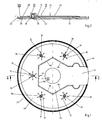
- Fig. 1 shows an optical display device with a light guide 14 for a not closer illustrated household electrical appliance, for example a kettle, etc.
- the Light guide 14 is made of polymethacryla and has the shape of a plate with an upper and a lower cover side 28, 30 (FIG. 2) and an end face serving as display surface 22.
- FOG. 2 cover side 28, 30
- end face serving as display surface 22.
- polycarbonate other light-conducting materials known to the person skilled in the art can also be used Materials are used, such as polycarbonate t etc.
- the display area 22 is adapted to a contour of a round household appliance and moves this over one large area.
- the display device has five luminous elements 10, specifically Glow lamps with a glass bulb, which essentially light 12 laterally all around a cylindrical surface of the glass bulb and a small part with an end face 32 blast a suction port 70 (Fig. 3).
- the light guide 14 has openings 36 in the luminous body 10 in the longitudinal direction in the direction of a normal 34 of the Light guide are inserted (Fig. 3).
- the luminous body 10 radiate a large part of it Light 12 all around parallel to the plate-shaped light guide 14.
- the light guide 14 encloses the filament 10 laterally all around and takes the emitted light 12 all around for forwarding to the display area 22 (FIGS. 1 and 3).
- the light guide 14 is fastened on a base plate 72 (FIG. 2).
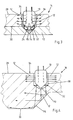
- the material thickness of the The light guide 14 is slightly thinner than the length of the glass bulb of the filament 10, so that the glass bulb in a through hole forming the opening 36 is largely completely enclosed (Fig. 3).
- the material thickness to the display surface 22 decreases (FIG. 2).
- the glass bulb protrudes with his Suction nozzle 70 over the lower cover side 30 of the light guide 14 into a conical Countersink 74 of the base plate 72.
- On a boundary surface formed by the countersink 74 24 is emitted via the end face 32 and is not directly coupled into the light guide 14 Light 12 coupled into the light guide 14 via scattering.
- Fig. 4 shows a variant of Fig. 3, in which the material thickness of an optical fiber 16 at least in the area of the filament 10 is thicker than the length of the glass bulb. Essentially constant components are numbered with the same reference numerals.
- the Luminous body 10 is inserted into an opening 38 formed by a blind hole.
- the Light 12 emitted by the luminous element 10 via the end face 32 is introduced into the light guide 16 coupled in and via a boundary surface 26 via total reflection to the display surface 22 headed.
- the light guide 14 has a recess 40 in the central region, not by one Coupling unit of the household appliance shown by the horizontally installed to guide plate-shaped light guide 14 (Fig. 1). That in the direction of the recess 40 radiated light 12 is arranged with a boundary surface in the area of the recess 40 42 deflected in the direction of the display surface 22.
- the boundary surface 42 is formed by an end face of the light guide 14 on which the total reflection Light 12 is redirected.
- the boundary surface 42 is made up of five straight segments 76, 78, 80, 82, 84 formed (Fig. 1), which in turn has two reflection surfaces in the longitudinal direction 44, 46 have (Fig. 5).
- the reflection surfaces 44, 46 are in the direction of the normal 34 inclined and close with the upper deck 28 or with the lower deck 30 each an angle 86, 88 of 45 degrees (Fig. 5). Meets parallel in the light guide 14 running light 12 on one of the reflection surfaces 44 or 46, this will at least reversed in one plane in its direction via total reflection and parallel in Light guide 14 directed to the display surface 22.
- the light 12 is scattered on the straight segments 76, 78, 80, 82, 84 (Fig. 6). By superimposing the light 12 from two luminous elements 10, it is targeted in one area 48 between the luminaries 10 increases the luminance, so that on the display surface 22 an overall uniform luminance arises.
- the light 12 is guided in the light guide 14 to the display surface 22 via total reflection.
- this is redirected in front of the display surface at two boundary surfaces 50, 52 via total reflection (Fig. 7).
- a refraction of the light 12 on the display surface 22 is shown in FIGS. 7, 8 and 9 graphically neglected.
- the boundary surfaces 50, 52 are offset by a Batch of light guide 14 reached.
- the first boundary surface 50 has one Angle 90 from 22.5 degrees, which is less than or equal to half a critical angle for total reflection.
- the light 12 running parallel in the plate-shaped light guide 14 is at the Boundary surface 50 deflected via total reflection to the boundary surface 52 hits this at an angle 92 of 45 degrees and is at an angle 94 of 45 degrees total reflection upwards from the display area 22 in a defined angular range 68 emitted.
- the display area is below eye level.
- the light 12 from the display surface 22 is advantageously used radiated upwards in the direction of a user's field of vision and is therefore special good to see. In order to prevent total reflection on the display surface 22, this is inclined at an angle 100 to the center of the light guide 14.
- Fig. 8 is a light guide 18 with four boundary surfaces 54, 56, 58, 60 are shown, at which the light 12 is deflected via total reflection. Constant components are generally numbered with the same reference numerals.
- the light 12 running parallel in the plate-shaped light guide 18 is transmitted by the two Boundary surfaces 54, 56 divided into two partial luminous fluxes.
- a first partial luminous flux is deflected at the boundary surface 54 and at the boundary surface 60 and in one Angle 96 emitted from the display surface 22 of approximately 45 degrees.
- a second partial luminous flux is reflected on the boundary surface 56 and on the boundary surface 58 and radiated parallel to the light guide 18 from the display surface 22.
- This from the display area 22 emerging light 12 can be from different positions, for example from a short distance, further away, at different heights of the device etc., can be recognized well.
- the division of the luminous flux into two partial luminous fluxes can also be done with a curved one Boundary surface 62 can be reached, as shown on a light guide 20 in Fig. 9 is.
- the light 12 is fanned out on the curved boundary surface 62 and redirected to two boundary surfaces 64, 66 via total reflection. At the boundary surfaces 64, 66 the light 12 is reflected and in an angular range 96 from the display area emitted.
- the Display area 22 is erosion-rough in order to scatter the light 12 and a total reflection to avoid on the display surface 22.
Landscapes
- Physics & Mathematics (AREA)
- General Physics & Mathematics (AREA)
- Optics & Photonics (AREA)
- Illuminated Signs And Luminous Advertising (AREA)
- Planar Illumination Modules (AREA)
- Cookers (AREA)
Abstract
Description
Die Aufgabe der Erfindung besteht darin, eine kostengünstige optische Anzeigevorrichtung mit einem hohen Wirkungsgrad zu schaffen. Die Aufgabe wird erfindungsgemäß durch die Merkmale des Anspruchs 1 gelöst, während vorteilhafte Ausgestaltungen und Weiterbildungen der Erfindung den Unteransprüchen entnommen werden können.
- Fig. 1
- eine Ansicht eines Lichtleiters von oben,
- Fig. 2
- einen Schnitt entlang der Linie II-II in Fig. 1,
- Fig. 3
- eine vergrößerte Ansicht des mit III gekennzeichneten Ausschnitts in Fig. 2,
- Fig. 4
- eine Variante nach Fig. 3,
- Fig. 5
- eine vergrößerte Ansicht des mit V gekennzeichneten Ausschnitts in Fig. 2,
- Fig. 6
- eine vergrößerte Ansicht des mit VI gekennzeichneten Ausschnitts in Fig. 1,
- Fig. 7
- eine vergrößerte Ansicht des mit VII gekennzeichneten Ausschnitts in Fig. 2 und
- Fig. 8 u. 9
- Varianten nach Fig. 6.
- 10
- Leuchtkörper
- 12
- Licht
- 14
- Lichtleiter
- 16
- Lichtleiter
- 18
- Lichtleiter
- 20
- Lichtleiter
- 22
- Anzeigefläche
- 24
- Begrenzungsfläche
- 26
- Begrenzungsfläche
- 28
- Deckseite
- 30
- Deckseite
- 32
- Stirnseite
- 34
- Normale
- 36
- Öffnung
- 38
- Öffnung
- 40
- Ausnehmung
- 42
- Begrenzungsfläche
- 44
- Reflexionsfläche
- 46
- Reflexionsfläche
- 48
- Bereich
- 50
- Begrenzungsfläche
- 52
- Begrenzungsfläche
- 54
- Begrenzungsfläche
- 56
- Begrenzungsfläche
- 58
- Begrenzungsfläche
- 60
- Begrenzungsfläche
- 62
- Begrenzungsfläche
- 64
- Begrenzungsfläche
- 66
- Begrenzungsfläche
- 68
- Winkelbereich
- 70
- Saugstutzen
- 72
- Bodenplatte
- 74
- Senkung
- 76
- Segment
- 78
- Segment
- 80
- Segment
- 82
- Segment
- 84
- Segment
- 86
- Winkel
- 88
- Winkel
- 90
- Winkel
- 92
- Winkel
- 94
- Winkel
- 96
- Winkelbereich
- 98
- Winkel
- 100
- Winkel
Claims (15)
- Optische Anzeigevorrichtung für elektrische Haushaltsgeräte mit zumindest einem Leuchtkörper (10) mit beliebiger Lichtabstrahlcharakteristik und mit zumindest einem Lichtleiter (14, 16, 18, 20), der eine Anzeigefläche (22) aufweist, dadurch gekennzeichnet, daß der Lichtleiter (14, 16, 18, 20) den Leuchtkörper (10) rundum zumindest in einem Bereich vollständig umschließt und rundum Licht (12) zur Weiterleitung zur Anzeigefläche (22) aufnimmt.
- Optische Anzeigevorrichtung nach Anspruch 1, dadurch gekennzeichnet, daß im Bereich des Leuchtkörpers (10) zumindest eine Begrenzungsfläche (24, 26) angeordnet ist, die zumindest ein Teil des nicht direkt in den Lichtleiter (14, 16) eingekoppelten Lichts (12) über Reflexion und/oder Streuung in den Lichtleiter (14, 16) einkoppelt.
- Optische Anzeigevorrichtung nach Anspruch 1 oder 2, dadurch gekennzeichnet, daß der Lichtleiter (14, 16, 18, 20) plattenförmig ausgebildet ist und eine obere und eine untere Deckseite (28, 30) sowie eine als Anzeigefläche (22) dienende Stirnseite aufweist.
- Optische Anzeigevorrichtung nach Anspruch 3, dadurch gekennzeichnet, daß die Anzeigefläche (22) des Lichtleiters (14, 16, 18, 20) der Kontur des Haushaltsgeräts angepaßt ist und das Haushaltsgerät über einen großen Bereich umzieht.
- Optische Anzeigevorrichtung nach Anspruch 3 oder 4, dadurch gekennzeichnet, daß der Lichtleiter (14, 16, 18, 20) mindestens eine Öffnung (36, 38) aufweist, in die der Leuchtkörper (10) in Längsrichtung im wesentlichen in Richtung einer Normalen (34) des plattenförmigen Lichtleiters (14, 16, 18, 20) eingesteckt ist und seitlich rundum Licht (12) im wesentlichen parallel zum Lichtleiter (14, 16, 18, 20) abstrahlt.
- Optische Anzeigevorrichtung nach Anspruch 5, dadurch gekennzeichnet, daß der Lichtleiter (14, 16, 18, 20) im mittleren Bereich zumindest eine Ausnehmung (40) aufweist und daß eine Begrenzungsfläche (42) im Bereich der Ausnehmung (40) das Licht (12) zur Anzeigefläche (22) umlenkt.
- Optische Anzeigevorrichtung nach Anspruch 6, dadurch gekennzeichnet, daß die Begrenzungsfläche (42) eine Stirnseite des Lichtleiters (14, 16, 18, 20) ist.
- Optische Anzeigevorrichtung nach Anspruch 7, dadurch gekennzeichnet, daß die Begrenzungsfläche (42) das Licht (12) über Totalreflexion und/oder Streuung zur Anzeigefläche (22) umlenkt.
- Optische Anzeigevorrichtung nach Anspruch 8, dadurch gekennzeichnet, daß die Begrenzungsfläche (42) aus zumindest einer in Richtung der Normalen (34) des Lichtleiters (14, 16, 18, 20) geneigten Reflexionsfläche (44, 46) besteht.
- Optische Anzeigevorrichtung nach Anspruch 8 oder 9, dadurch gekennzeichnet, daß der Lichtleiter (14, 16, 18, 20) aus einem Material mit einem Grenzwinkel für Totalreflexion kleiner als 45 Grad ist und die Begrenzungsfläche (42) mit zwei um 45 Grad geneigten Reflexionsflächen (44, 46) die Richtung des Lichts (12) in zumindest einer Ebene umkehrt.
- Optische Anzeigevorrichtung nach einem der Ansprüche 6 bis 10, dadurch gekennzeichnet, daß die Begrenzungsfläche (42) das Licht (12) gezielt in zumindest einen Bereich (48) der Anzeigefläche (22) zur Verstärkung der Leuchtdichte lenkt.
- Optische Anzeigevorrichtung nach einem der vorhergehenden Ansprüche, dadurch gekennzeichnet, daß der Leuchtkörper (10) eine Glimmlampe ist.
- Optische Anzeigevorrichtung nach einem der vorhergehenden Ansprüche, dadurch gekennzeichnet, daß der Lichtleiter (14, 16, 18, 20) das Licht (12) über Totalreflexion zur Anzeigefläche (22) leitet.
- Optische Anzeigevorrichtung nach einem der vorhergehenden Ansprüche, dadurch gekennzeichnet, daß zumindest eine Begrenzungsfläche (50, 52, 54, 56, 58, 60, 62, 64, 66) das Licht (12) vor der Anzeigefläche (22) umlenkt, so daß das Licht (12) in einem definierten Winkelbereich (68, 96) aus der Anzeigefläche (22) austritt.
- Optische Anzeigevorrichtung nach einem der vorhergehenden Ansprüche, dadurch gekennzeichnet, daß die Anzeigefläche (22) eine unglatte Oberflächenkontur aufweist und das Licht (12) streut.
Applications Claiming Priority (2)
| Application Number | Priority Date | Filing Date | Title |
|---|---|---|---|
| DE19903587 | 1999-01-29 | ||
| DE19903587A DE19903587A1 (de) | 1999-01-29 | 1999-01-29 | Optische Anzeigevorrichtung für elektrische Haushaltsgeräte |
Publications (2)
| Publication Number | Publication Date |
|---|---|
| EP1030102A1 true EP1030102A1 (de) | 2000-08-23 |
| EP1030102B1 EP1030102B1 (de) | 2007-09-12 |
Family
ID=7895818
Family Applications (1)
| Application Number | Title | Priority Date | Filing Date |
|---|---|---|---|
| EP00101112A Expired - Lifetime EP1030102B1 (de) | 1999-01-29 | 2000-01-20 | Optische Anzeigevorrichtung für elektrische Haushaltsgeräte |
Country Status (3)
| Country | Link |
|---|---|
| EP (1) | EP1030102B1 (de) |
| AT (1) | ATE373200T1 (de) |
| DE (2) | DE19903587A1 (de) |
Families Citing this family (6)
| Publication number | Priority date | Publication date | Assignee | Title |
|---|---|---|---|---|
| GB2367999B (en) * | 2000-10-20 | 2004-02-18 | Pulse Home Products Ltd | Liquid heating vessel |
| DE10102585A1 (de) * | 2001-01-20 | 2002-07-25 | Philips Corp Intellectual Pty | Farbige Beleuchtungseinrichtung |
| DE10102586A1 (de) * | 2001-01-20 | 2002-07-25 | Philips Corp Intellectual Pty | Beleuchtungseinrichtung mit punktförmigen Lichtquellen |
| DE10102587A1 (de) * | 2001-01-20 | 2002-07-25 | Philips Corp Intellectual Pty | Beleuchtungseinrichtung mit Linienförmigen Lichtquellen |
| DE10144666B4 (de) * | 2001-09-11 | 2004-02-05 | BSH Bosch und Siemens Hausgeräte GmbH | Ansteuerung eines Leuchtrings |
| DE10333316A1 (de) * | 2003-07-22 | 2005-02-10 | BSH Bosch und Siemens Hausgeräte GmbH | Lichtleiterbauteil für optische Mehrsegmentsanzeigen |
Citations (4)
| Publication number | Priority date | Publication date | Assignee | Title |
|---|---|---|---|---|
| US3262224A (en) * | 1960-12-07 | 1966-07-26 | George K C Hardesty | Composite illumination device |
| US3264769A (en) * | 1960-12-07 | 1966-08-09 | George K C Hardesty | Illuminated fixed indicia indicating device |
| DE29513771U1 (de) * | 1995-08-25 | 1995-10-19 | Prust Joerg | Beleuchtungs- und Anzeigesystem für Displays und Instrumente |
| GB2312153A (en) * | 1996-04-19 | 1997-10-22 | Bosch Siemens Hausgeraete | Electrical appliance with optical indicating means |
Family Cites Families (7)
| Publication number | Priority date | Publication date | Assignee | Title |
|---|---|---|---|---|
| US2831453A (en) * | 1956-07-26 | 1958-04-22 | George K C Hardesty | Illuminated panel, dial and/or pointer by geometrical surfaces |
| DE1198754B (de) * | 1960-04-08 | 1965-08-19 | Gen Electric | Lichtverteileranordnung |
| DE3919925A1 (de) * | 1989-06-19 | 1990-12-20 | Inotec Gmbh Ges Fuer Innovativ | Beleuchtete, anzeigeeinheit, insbesondere hausnummer, verkehrsschild, werbetraeger |
| DE9111037U1 (de) * | 1991-09-06 | 1992-05-07 | Licentia Patent-Verwaltungs-Gmbh, 6000 Frankfurt | Optische Betriebsanzeigevorrichtung für elektrische Haushalts-Tischgeräte |
| DE29514771U1 (de) * | 1995-09-14 | 1995-12-07 | Renic Anton | Beleuchtbare Anzeigeeinheit |
| DE19610816C2 (de) * | 1996-03-19 | 1999-02-04 | Ctx Opto Electronics Corp | Hintergrundbeleuchtungssystem für eine Anzeigetafel |
| DE19652829B4 (de) * | 1996-04-19 | 2008-04-30 | BSH Bosch und Siemens Hausgeräte GmbH | Wasserkocher mit Betriebsanzeige |
-
1999
- 1999-01-29 DE DE19903587A patent/DE19903587A1/de not_active Withdrawn
-
2000
- 2000-01-20 DE DE50014637T patent/DE50014637D1/de not_active Expired - Lifetime
- 2000-01-20 EP EP00101112A patent/EP1030102B1/de not_active Expired - Lifetime
- 2000-01-20 AT AT00101112T patent/ATE373200T1/de not_active IP Right Cessation
Patent Citations (4)
| Publication number | Priority date | Publication date | Assignee | Title |
|---|---|---|---|---|
| US3262224A (en) * | 1960-12-07 | 1966-07-26 | George K C Hardesty | Composite illumination device |
| US3264769A (en) * | 1960-12-07 | 1966-08-09 | George K C Hardesty | Illuminated fixed indicia indicating device |
| DE29513771U1 (de) * | 1995-08-25 | 1995-10-19 | Prust Joerg | Beleuchtungs- und Anzeigesystem für Displays und Instrumente |
| GB2312153A (en) * | 1996-04-19 | 1997-10-22 | Bosch Siemens Hausgeraete | Electrical appliance with optical indicating means |
Also Published As
| Publication number | Publication date |
|---|---|
| DE19903587A1 (de) | 2000-08-03 |
| DE50014637D1 (de) | 2007-10-25 |
| EP1030102B1 (de) | 2007-09-12 |
| ATE373200T1 (de) | 2007-09-15 |
Similar Documents
| Publication | Publication Date | Title |
|---|---|---|
| DE2634264A1 (de) | Halbleiter-lumineszenzbauelement | |
| EP1378771B1 (de) | Innenraumleuchte | |
| DE3542292A1 (de) | Leuchte fuer ein kraftfahrzeug | |
| EP2556394B1 (de) | Leuchtmodul und leuchte mit leuchtmodul | |
| DE102004046386A1 (de) | Lichtleiter für Leuchten, insbesondere für Leuchten von Kraftfahrzeugen | |
| EP3015761B1 (de) | Leuchtenbaugruppe mit optischem element | |
| DE19957611A1 (de) | Beleuchtungsanordnung | |
| EP1496380B1 (de) | Leuchtelement mit einer Leuchtdiode | |
| EP1025386A1 (de) | Beleuchtungskörper für schwimmbäder und ähnliches | |
| EP1030102B1 (de) | Optische Anzeigevorrichtung für elektrische Haushaltsgeräte | |
| EP1152186A1 (de) | Beleuchtungsvorrichtung und Verfahren zur Beleuchtung | |
| DE19758551B4 (de) | Fahrradrückleuchte mit mindestens zwei Leuchtdioden | |
| DE10149044A1 (de) | Fahrzeugleuchte | |
| DE10143544A1 (de) | Beleuchtungseinrichtung | |
| EP2587134A1 (de) | Leuchte | |
| DE10129972A1 (de) | Beleuchtungseinrichtung | |
| EP2603732B1 (de) | Anordnung zur lichtabgabe mit lichtlenkelement und reflektor | |
| DE20317444U1 (de) | Beleuchtungsvorrichtung, insbesondere für Straßen, Wege, Plätze o.dgl. | |
| DE69529012T2 (de) | Lichtleiter mit Weitwinkelausgang | |
| EP1674899B1 (de) | Beleuchtungseinrichtung | |
| EP3591281B1 (de) | Innenraumleuchte | |
| EP2435751B1 (de) | Elektrische lampe | |
| EP1275899B1 (de) | Downlight mit Seitenreflektor | |
| DE69803507T2 (de) | Anzeigeorgan mit lichtemittierender Diode | |
| WO2008046394A2 (de) | Beleuchtungsvorrichtung |
Legal Events
| Date | Code | Title | Description |
|---|---|---|---|
| PUAI | Public reference made under article 153(3) epc to a published international application that has entered the european phase |
Free format text: ORIGINAL CODE: 0009012 |
|
| AK | Designated contracting states |
Kind code of ref document: A1 Designated state(s): AT BE CH CY DE DK ES FI FR GB GR IE IT LI LU MC NL PT SE |
|
| AX | Request for extension of the european patent |
Free format text: AL;LT;LV;MK;RO;SI |
|
| 17P | Request for examination filed |
Effective date: 20000928 |
|
| AKX | Designation fees paid |
Free format text: AT BE CH CY DE DK ES FI FR GB GR IE IT LI LU MC NL PT SE |
|
| RAP1 | Party data changed (applicant data changed or rights of an application transferred) |
Owner name: BSH BOSCH UND SIEMENS HAUSGERAETE GMBH |
|
| GRAP | Despatch of communication of intention to grant a patent |
Free format text: ORIGINAL CODE: EPIDOSNIGR1 |
|
| GRAS | Grant fee paid |
Free format text: ORIGINAL CODE: EPIDOSNIGR3 |
|
| GRAA | (expected) grant |
Free format text: ORIGINAL CODE: 0009210 |
|
| AK | Designated contracting states |
Kind code of ref document: B1 Designated state(s): AT BE CH CY DE DK ES FI FR GB GR IE IT LI LU MC NL PT SE |
|
| REG | Reference to a national code |
Ref country code: GB Ref legal event code: FG4D Free format text: NOT ENGLISH |
|
| REG | Reference to a national code |
Ref country code: CH Ref legal event code: EP |
|
| GBT | Gb: translation of ep patent filed (gb section 77(6)(a)/1977) |
Effective date: 20070912 |
|
| REF | Corresponds to: |
Ref document number: 50014637 Country of ref document: DE Date of ref document: 20071025 Kind code of ref document: P |
|
| REG | Reference to a national code |
Ref country code: IE Ref legal event code: FG4D Free format text: LANGUAGE OF EP DOCUMENT: GERMAN |
|
| ET | Fr: translation filed | ||
| PG25 | Lapsed in a contracting state [announced via postgrant information from national office to epo] |
Ref country code: FI Free format text: LAPSE BECAUSE OF FAILURE TO SUBMIT A TRANSLATION OF THE DESCRIPTION OR TO PAY THE FEE WITHIN THE PRESCRIBED TIME-LIMIT Effective date: 20070912 |
|
| NLV1 | Nl: lapsed or annulled due to failure to fulfill the requirements of art. 29p and 29m of the patents act | ||
| PG25 | Lapsed in a contracting state [announced via postgrant information from national office to epo] |
Ref country code: NL Free format text: LAPSE BECAUSE OF FAILURE TO SUBMIT A TRANSLATION OF THE DESCRIPTION OR TO PAY THE FEE WITHIN THE PRESCRIBED TIME-LIMIT Effective date: 20070912 Ref country code: GR Free format text: LAPSE BECAUSE OF FAILURE TO SUBMIT A TRANSLATION OF THE DESCRIPTION OR TO PAY THE FEE WITHIN THE PRESCRIBED TIME-LIMIT Effective date: 20071213 Ref country code: ES Free format text: LAPSE BECAUSE OF FAILURE TO SUBMIT A TRANSLATION OF THE DESCRIPTION OR TO PAY THE FEE WITHIN THE PRESCRIBED TIME-LIMIT Effective date: 20071223 |
|
| REG | Reference to a national code |
Ref country code: IE Ref legal event code: FD4D |
|
| PG25 | Lapsed in a contracting state [announced via postgrant information from national office to epo] |
Ref country code: PT Free format text: LAPSE BECAUSE OF FAILURE TO SUBMIT A TRANSLATION OF THE DESCRIPTION OR TO PAY THE FEE WITHIN THE PRESCRIBED TIME-LIMIT Effective date: 20080212 |
|
| PG25 | Lapsed in a contracting state [announced via postgrant information from national office to epo] |
Ref country code: SE Free format text: LAPSE BECAUSE OF FAILURE TO SUBMIT A TRANSLATION OF THE DESCRIPTION OR TO PAY THE FEE WITHIN THE PRESCRIBED TIME-LIMIT Effective date: 20071212 |
|
| PLBE | No opposition filed within time limit |
Free format text: ORIGINAL CODE: 0009261 |
|
| STAA | Information on the status of an ep patent application or granted ep patent |
Free format text: STATUS: NO OPPOSITION FILED WITHIN TIME LIMIT |
|
| BERE | Be: lapsed |
Owner name: BSH BOSCH UND SIEMENS HAUSGERATE G.M.B.H. Effective date: 20080131 |
|
| PG25 | Lapsed in a contracting state [announced via postgrant information from national office to epo] |
Ref country code: DK Free format text: LAPSE BECAUSE OF FAILURE TO SUBMIT A TRANSLATION OF THE DESCRIPTION OR TO PAY THE FEE WITHIN THE PRESCRIBED TIME-LIMIT Effective date: 20070912 |
|
| 26N | No opposition filed |
Effective date: 20080613 |
|
| PG25 | Lapsed in a contracting state [announced via postgrant information from national office to epo] |
Ref country code: MC Free format text: LAPSE BECAUSE OF NON-PAYMENT OF DUE FEES Effective date: 20080131 |
|
| REG | Reference to a national code |
Ref country code: CH Ref legal event code: PL |
|
| PG25 | Lapsed in a contracting state [announced via postgrant information from national office to epo] |
Ref country code: IE Free format text: LAPSE BECAUSE OF FAILURE TO SUBMIT A TRANSLATION OF THE DESCRIPTION OR TO PAY THE FEE WITHIN THE PRESCRIBED TIME-LIMIT Effective date: 20070912 Ref country code: LI Free format text: LAPSE BECAUSE OF NON-PAYMENT OF DUE FEES Effective date: 20080131 Ref country code: CH Free format text: LAPSE BECAUSE OF NON-PAYMENT OF DUE FEES Effective date: 20080131 |
|
| PG25 | Lapsed in a contracting state [announced via postgrant information from national office to epo] |
Ref country code: BE Free format text: LAPSE BECAUSE OF NON-PAYMENT OF DUE FEES Effective date: 20080131 |
|
| PG25 | Lapsed in a contracting state [announced via postgrant information from national office to epo] |
Ref country code: AT Free format text: LAPSE BECAUSE OF NON-PAYMENT OF DUE FEES Effective date: 20080120 |
|
| PG25 | Lapsed in a contracting state [announced via postgrant information from national office to epo] |
Ref country code: CY Free format text: LAPSE BECAUSE OF FAILURE TO SUBMIT A TRANSLATION OF THE DESCRIPTION OR TO PAY THE FEE WITHIN THE PRESCRIBED TIME-LIMIT Effective date: 20070912 |
|
| PG25 | Lapsed in a contracting state [announced via postgrant information from national office to epo] |
Ref country code: LU Free format text: LAPSE BECAUSE OF NON-PAYMENT OF DUE FEES Effective date: 20080120 |
|
| PG25 | Lapsed in a contracting state [announced via postgrant information from national office to epo] |
Ref country code: IT Free format text: LAPSE BECAUSE OF NON-PAYMENT OF DUE FEES Effective date: 20080131 |
|
| REG | Reference to a national code |
Ref country code: FR Ref legal event code: PLFP Year of fee payment: 16 |
|
| REG | Reference to a national code |
Ref country code: DE Ref legal event code: R081 Ref document number: 50014637 Country of ref document: DE Owner name: BSH HAUSGERAETE GMBH, DE Free format text: FORMER OWNER: BSH BOSCH UND SIEMENS HAUSGERAETE GMBH, 81739 MUENCHEN, DE Effective date: 20150402 |
|
| REG | Reference to a national code |
Ref country code: FR Ref legal event code: CD Owner name: BSH HAUSGERATE GMBH Effective date: 20151022 |
|
| REG | Reference to a national code |
Ref country code: FR Ref legal event code: PLFP Year of fee payment: 17 |
|
| REG | Reference to a national code |
Ref country code: FR Ref legal event code: PLFP Year of fee payment: 18 |
|
| REG | Reference to a national code |
Ref country code: FR Ref legal event code: PLFP Year of fee payment: 19 |
|
| PGFP | Annual fee paid to national office [announced via postgrant information from national office to epo] |
Ref country code: GB Payment date: 20180125 Year of fee payment: 19 Ref country code: DE Payment date: 20180131 Year of fee payment: 19 |
|
| PGFP | Annual fee paid to national office [announced via postgrant information from national office to epo] |
Ref country code: FR Payment date: 20180124 Year of fee payment: 19 |
|
| REG | Reference to a national code |
Ref country code: DE Ref legal event code: R119 Ref document number: 50014637 Country of ref document: DE |
|
| GBPC | Gb: european patent ceased through non-payment of renewal fee |
Effective date: 20190120 |
|
| PG25 | Lapsed in a contracting state [announced via postgrant information from national office to epo] |
Ref country code: FR Free format text: LAPSE BECAUSE OF NON-PAYMENT OF DUE FEES Effective date: 20190131 Ref country code: DE Free format text: LAPSE BECAUSE OF NON-PAYMENT OF DUE FEES Effective date: 20190801 |
|
| PG25 | Lapsed in a contracting state [announced via postgrant information from national office to epo] |
Ref country code: GB Free format text: LAPSE BECAUSE OF NON-PAYMENT OF DUE FEES Effective date: 20190120 |