EP1029441A2 - Ballenpresse für Astrückstände - Google Patents
Ballenpresse für Astrückstände Download PDFInfo
- Publication number
- EP1029441A2 EP1029441A2 EP00200031A EP00200031A EP1029441A2 EP 1029441 A2 EP1029441 A2 EP 1029441A2 EP 00200031 A EP00200031 A EP 00200031A EP 00200031 A EP00200031 A EP 00200031A EP 1029441 A2 EP1029441 A2 EP 1029441A2
- Authority
- EP
- European Patent Office
- Prior art keywords
- machine
- rotors
- chamber
- rotor
- tube
- Prior art date
- Legal status (The legal status is an assumption and is not a legal conclusion. Google has not performed a legal analysis and makes no representation as to the accuracy of the status listed.)
- Withdrawn
Links
Images


Classifications
-
- A—HUMAN NECESSITIES
- A01—AGRICULTURE; FORESTRY; ANIMAL HUSBANDRY; HUNTING; TRAPPING; FISHING
- A01F—PROCESSING OF HARVESTED PRODUCE; HAY OR STRAW PRESSES; DEVICES FOR STORING AGRICULTURAL OR HORTICULTURAL PRODUCE
- A01F15/00—Baling presses for straw, hay or the like
- A01F15/07—Rotobalers, i.e. machines for forming cylindrical bales by winding and pressing
-
- A—HUMAN NECESSITIES
- A01—AGRICULTURE; FORESTRY; ANIMAL HUSBANDRY; HUNTING; TRAPPING; FISHING
- A01D—HARVESTING; MOWING
- A01D90/00—Vehicles for carrying harvested crops with means for selfloading or unloading
- A01D90/02—Loading means
- A01D90/04—Loading means with additional cutting means
-
- A—HUMAN NECESSITIES
- A01—AGRICULTURE; FORESTRY; ANIMAL HUSBANDRY; HUNTING; TRAPPING; FISHING
- A01D—HARVESTING; MOWING
- A01D90/00—Vehicles for carrying harvested crops with means for selfloading or unloading
- A01D90/02—Loading means
- A01D90/04—Loading means with additional cutting means
- A01D90/06—Loading means with additional cutting means with chaff cutters, i.e. choppers used as loading and cutting means
-
- A—HUMAN NECESSITIES
- A01—AGRICULTURE; FORESTRY; ANIMAL HUSBANDRY; HUNTING; TRAPPING; FISHING
- A01F—PROCESSING OF HARVESTED PRODUCE; HAY OR STRAW PRESSES; DEVICES FOR STORING AGRICULTURAL OR HORTICULTURAL PRODUCE
- A01F15/00—Baling presses for straw, hay or the like
- A01F15/08—Details
- A01F15/10—Feeding devices for the crop material e.g. precompression devices
- A01F15/106—Feeding devices for the crop material e.g. precompression devices for round balers
-
- A—HUMAN NECESSITIES
- A01—AGRICULTURE; FORESTRY; ANIMAL HUSBANDRY; HUNTING; TRAPPING; FISHING
- A01F—PROCESSING OF HARVESTED PRODUCE; HAY OR STRAW PRESSES; DEVICES FOR STORING AGRICULTURAL OR HORTICULTURAL PRODUCE
- A01F15/00—Baling presses for straw, hay or the like
- A01F15/08—Details
- A01F15/14—Tying devices specially adapted for baling presses
- A01F15/141—Tying devices specially adapted for baling presses for round balers
-
- A—HUMAN NECESSITIES
- A01—AGRICULTURE; FORESTRY; ANIMAL HUSBANDRY; HUNTING; TRAPPING; FISHING
- A01F—PROCESSING OF HARVESTED PRODUCE; HAY OR STRAW PRESSES; DEVICES FOR STORING AGRICULTURAL OR HORTICULTURAL PRODUCE
- A01F15/00—Baling presses for straw, hay or the like
- A01F15/07—Rotobalers, i.e. machines for forming cylindrical bales by winding and pressing
- A01F2015/0775—Pressing chambers with fix volume
-
- A—HUMAN NECESSITIES
- A01—AGRICULTURE; FORESTRY; ANIMAL HUSBANDRY; HUNTING; TRAPPING; FISHING
- A01F—PROCESSING OF HARVESTED PRODUCE; HAY OR STRAW PRESSES; DEVICES FOR STORING AGRICULTURAL OR HORTICULTURAL PRODUCE
- A01F15/00—Baling presses for straw, hay or the like
- A01F15/08—Details
- A01F15/10—Feeding devices for the crop material e.g. precompression devices
- A01F2015/108—Cutting devices comprising cutter and counter-cutter
Definitions
- This invention relates to a baling machine for pruning residues, a typical but not exclusive use of which is in gathering cut-off vine branches.
- Said pruning residues are usually heaped together on a suitable site and then burned, it being uneconomical to form them into faggots because of the lengthy time and effort required.
- the main object of this invention is therefore to provide a machine able to gather such pruning residues from the ground and to form them into bales usable for heating and other purposes, all within the context of a rational, reliable and robust construction of small overall size.
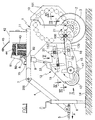
- a towed frame provided at its front with a gathering unit able to swivel in a longitudinal vertical plane in order to occupy a raised rest position for machine transfer along the road, and a lowered working position in which it lies a short distance from the ground, from which it gathers the branches to serve them to a rearward chamber for their compacting and binding.
- Said gathering unit comprises a lower pair of transverse pronged rotors rotating in the opposite direction to the direction of travel, and with which there cooperate an overlying pair of transverse pronged rotors rotated in the opposite direction to the preceding, between said pairs of rotors there being defined a downstream-tapering conveying channel opening into said compacting chamber.
- This latter is of cylindrical shape with its horizontal longitudinal axis positioned transverse to the travel direction, and comprises a fixed front part, and a movable rear part acting as a discharge door for the compacted and bound material.
- said cylindrical chamber is defined by a circumferential series of transverse ribbed rollers rotating in the same direction and interrupted at the communication with said chamber.
- said movements derive from a hydraulic motor fed by the hydraulic pump usually present on the tractor.
- Said tractor (not shown) is provided with a usual power take-off and a likewise usual hydraulic pump, for the requirements stated hereinafter.
- the frame 1 comprises a cross-member 70 to which there is hinged, on the transverse pin 8, a ring 80 slidingly mounted on the body of a hydraulic cylinder-piston unit 9, the rod of which is pivoted to a holed lug 33 projecting upwards from the underlying gathering unit indicated by 12.
- Said ring 80 rests below the edge of an overlying skirt 81 fixed to the top of the cylinder-piston unit 9, an underlying spring 82 being provided to allow the cylinder-piston unit 9 to slide upwards relative to said ring 80 when the independent idle front wheels of said gathering unit 12 encounter roughness on the ground 14.
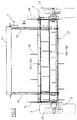
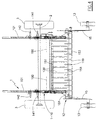
- the unit 12 comprises two vertically-lying opposing side plates 15 which support said wheels 13, and are connected together by two overlying frame-shaped flat structures, the lower of which is indicated by 150 ( Figures 2, 3 and 5) and the upper by 151 ( Figures 2, 4 and 5).
- Each of the two plates 15 is individually connected to a rearward vertical containing plate 16 inclined towards the machine centre and towards the respective side 10 of the frame 1 (see Figures 3 and 5), and lowerly provided (see Figure 1) with a projecting arm 170, which is hinged on the lower transverse axis 100 of the frame 1.
- All the rotors consist of a shaft provided with a plurality of flat prongs or teeth suitably spaced apart longitudinally and radially, said prongs being suitably offset.
- the first rotor 18, which is the actual gathering rotor, has a greater diameter than the others.
- Said panels 152 and 153 are provided with corresponding passage slots for said prongs, the slots being indicated by 117, 118, 119 and 120 for the rotors 17, 18, 19 and 20 respectively.
- the lower panel 152 has a further series of slots 121 for passage of the flat prongs of a further rotor 21 positioned at the loading mouth of a compacting chamber for the pruning residues.
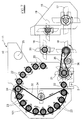
- Said compacting chamber is of cylindrical shape with its horizontal axis positioned transverse to the machine longitudinal axis and is formed partly by the sides 10 of the frame 1 and partly by a swivel shell 101 acting as the discharge door for the bales (not shown).
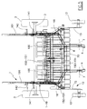
- rollers associated with the sides 10 of the frame 1 are indicated by 22 and those associated with the door 101 are indicated by 23, the upper roller indicated by 24 being common to said two parts of the compacting chamber and having its shaft acting as the hinge shaft for the door 101.
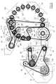
- the shaft 25 can be connected to a hydraulic motor fed by the tractor hydraulic pump via suitable valves.
- the chain 26 extends endlessly about the smaller-diameter drive sprocket of said shaft 25 and a sprocket keyed onto the shaft of the rotor 21, and is deviated about two chain tensioners indicated by 29.
- the chain 28 extends endlessly about the larger-diameter drive sprocket of the shaft 25 and a sprocket keyed onto the swivel shaft 24 of the door 101, and is deviated about the chain tensioner indicated by 30.
- a second drive sprocket of diameter less than the preceding provided for driving a chain 27 extending endlessly about the sprockets keyed onto the rotation shafts of those ribbed rollers 22 associated with the fixed part of the compacting chamber, and deviated about the chain tensioner indicated by 31.
- rollers 23 associated with the door 101 of the compacting chamber are driven by the drive chain shown in Figure 7 and indicated by the reference numeral 32.
- This latter extends endlessly about said drive sprocket, a driven sprocket keyed onto the rotation shaft of the rotor 17, and an idle sprocket 39 supported by the plate 15, and is deviated about a sprocket keyed onto the rotation shaft of the rotor 19 and about a chain tensioner indicated by 130.
- a chain 40 extends endlessly about this drive sprocket and about a sprocket keyed onto the rotation shaft of the rotor 20, and is deviated about the chain tensioner 38.
- the compacting chamber discharge door 101 is opened by two opposite hydraulic cylinder-piston units 41 hinged lowerly on respective pins 141 (see Figures 3 to 5) fixed to the sides 10 of the frame 1 and hinged upperly on pins 142 rigid with said door 101.
- Said cylinder-piston units 41 are controlled by an electrical or lever-operated hydraulic distributor positioned on the tractor dashboard.
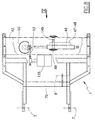
- Said means are contained in a cowling 42 positioned on the cross-member 11 of the frame 1, behind a holder 43 containing reels 44 of thread 45 in the form of a cord of natural or synthetic material (see Figure 1).
- these means comprise a through-rod horizontal hydraulic cylinder-piston unit 46 connected to the hydraulic distributor located on the tractor dashboard and extending transverse to the machine travel direction A.
- the through rod of the cylinder-piston unit 46 is fixed to the roof of the cowling 42, the body of the unit 46 being provided with a rack bar 47 which engages an underlying toothed sector 48.
- Said sector 48 is fixed to a longitudinal spindle 149 rotatably mounted on said cowling 42 and rigidly carrying a guide tube 49, known as a needle, through which the thread 45 passes freely.
- said thread guide tube 49 occupies the horizontal position shown by full lines in Figure 9, with a length of thread 45 hanging freely from the free end of it.
- a cutting unit comprising a disc blade 50 of vertical axis, positioned immediately above the cross-member 11 of the frame 1 and below the free end of the tube 49 when this is stationary in its horizontal position as stated.
- Said blade 50 is keyed onto the output shaft of a right angled transmission system 51, the input shaft of which is driven by a belt 53 deriving its movement from a step-down gear 125 driven by the shaft 25 ( Figures 6, 9).
- this member comprising a block 54 (see Figure 10) which in that side facing said blade 50 comprises a cross-shaped recess.
- the vertical groove of said cross-shaped recess which is less deep than the horizontal groove, is arranged to receive and retain the thread 45 at the moment of cutting, whereas the horizontal groove receives the facing part of the blade 50.
- the block 54 is fixed to a projecting appendix 55 hinged, on the transverse horizontal axis indicated by 56 in Figure 10, to the rear wall of the cowling 42.
- the block 54 is able to occupy an inactive position (to the right in Figure 10) in which it enables the thread to run freely downwards and follow the swing movements of the tube 49, and an active position (to the left in the figure) in which it operates as stated, with the tube 49 at that moment stationary.
- Said active and inactive positions of the block 54 are determined by a fork 59 which is fixed to said appendix 55, and between the arms of which there is inserted, with clearance, a peg 58 fixed to the spindle 149 in a position perpendicular to the thread guide tube 49.
- the fork 59 is virtually insensitive to the usual oscillation to which the peg 58 is subjected during bale formation, whereas the said fork 59 undergoes a large swing when the tube 49 becomes positioned horizontally on termination of binding, with the block 54 facing the blade 50.
- the invention also comprises a pressure gauge associated with the compacting chamber, preferably of adjustable type, and at least one warning device able to warn the operator when the bale has attained the chosen compactness.
- Said warning device can be an acoustic or visual device, both being preferably provided.
- the invention operates in the following manner.
- the operator halts the tractor to enable that mass of branches at that moment lying between the front lower rotor 17 and the chamber compartment to enter this latter.
- Said thread portion then becomes entangled with the branches of the rotating bale, which unwinds the thread 45 from the reel 44, to wind it as a spiral about the bale by the combined effect of the rotary movement of the bale and the swinging movement of the thread guide tube 49.
- the operator extends the cylinder-piston units 41 to discharge the bound bale, then retracts them to close the operating chamber, after which he restarts the tractor to commence a new pruning residue gathering and compacting operation.
Landscapes
- Life Sciences & Earth Sciences (AREA)
- Environmental Sciences (AREA)
- Harvester Elements (AREA)
- Harvesting Machines For Specific Crops (AREA)
- Scissors And Nippers (AREA)
Applications Claiming Priority (2)
| Application Number | Priority Date | Filing Date | Title |
|---|---|---|---|
| ITRE990022 | 1999-02-17 | ||
| IT1999RE000022A IT1310945B1 (it) | 1999-02-17 | 1999-02-17 | Imballatrice di residui di potatura. |
Publications (2)
| Publication Number | Publication Date |
|---|---|
| EP1029441A2 true EP1029441A2 (de) | 2000-08-23 |
| EP1029441A3 EP1029441A3 (de) | 2000-12-27 |
Family
ID=11399378
Family Applications (1)
| Application Number | Title | Priority Date | Filing Date |
|---|---|---|---|
| EP00200031A Withdrawn EP1029441A3 (de) | 1999-02-17 | 2000-01-24 | Ballenpresse für Astrückstände |
Country Status (2)
| Country | Link |
|---|---|
| EP (1) | EP1029441A3 (de) |
| IT (1) | IT1310945B1 (de) |
Cited By (7)
| Publication number | Priority date | Publication date | Assignee | Title |
|---|---|---|---|---|
| WO2003026388A1 (es) * | 2001-08-20 | 2003-04-03 | Recuperacion Y Tratamiento De Biomasa-Trabisa S.L. | Maquinaria para el aprovechamiento de residuos forestales agrico las y/o urbanos |
| EP1413191A1 (de) * | 2002-10-24 | 2004-04-28 | Deere & Company | Presse |
| EP1413190A1 (de) * | 2002-10-24 | 2004-04-28 | Deere & Company | Erntebergungsmaschine |
| US6874311B2 (en) | 2002-10-24 | 2005-04-05 | Deere & Company | Crop recovery machine |
| WO2007137803A1 (en) * | 2006-05-30 | 2007-12-06 | Claudio Bonamini | Agricultural machine for collecting and bundling vine branches |
| ITPD20120049A1 (it) * | 2012-02-24 | 2013-08-25 | Valentini Antonio S R L | Macchina roto-imballatrice per sarmenti |
| CN107211661A (zh) * | 2017-07-07 | 2017-09-29 | 马鞍山市志诚科技有限公司 | 一种带切割功能的农业打捆机 |
Family Cites Families (9)
| Publication number | Priority date | Publication date | Assignee | Title |
|---|---|---|---|---|
| DE2443838C3 (de) * | 1974-09-13 | 1982-09-02 | Gebrüder Welger GmbH & Co KG, 3340 Wolfenbüttel | Aufsammel-Rollballenpresse |
| DE2525491A1 (de) * | 1975-06-07 | 1976-12-16 | Welger Geb | Rollballenpresse fuer landwirtschaftliche halmgueter mit einer bindegarn- abschneidevorrichtung |
| ES476762A1 (es) * | 1979-01-11 | 1979-06-01 | Pomar Goma J Maria | Sistema mecanico de distribucion de hilo en el atado de pa- cas en maquinas rotoempacadoras. |
| FR2506117B1 (fr) * | 1981-05-22 | 1985-06-14 | Meslong Robert | Machine pour collecter les sarments de vigne |
| IT1157807B (it) * | 1982-02-05 | 1987-02-18 | Walter Monari | Macchina raccoglimballatrice in particolare per la raccolta di sarmenti o simili |
| EP0121279B1 (de) * | 1983-03-29 | 1989-10-04 | Ford New Holland N.V. | Rundballenpresse |
| DE3414080A1 (de) * | 1984-04-13 | 1985-10-24 | Klöckner-Humboldt-Deutz AG Zweigniederlassung Fahr, 7702 Gottmadingen | Vorrichtung zum binden von rollballen aus landwirtschaftlichem erntegut |
| DE3445050A1 (de) * | 1984-12-11 | 1986-06-12 | Hans 8602 Wachenroth Thomann | Verbundschnitt-schneidewerk fuer grossballenpressen (rundballenpressen) |
| DE19616999A1 (de) * | 1996-04-27 | 1997-10-30 | Deere & Co | Aufnehmer |
-
1999
- 1999-02-17 IT IT1999RE000022A patent/IT1310945B1/it active
-
2000
- 2000-01-24 EP EP00200031A patent/EP1029441A3/de not_active Withdrawn
Non-Patent Citations (1)
| Title |
|---|
| None |
Cited By (9)
| Publication number | Priority date | Publication date | Assignee | Title |
|---|---|---|---|---|
| WO2003026388A1 (es) * | 2001-08-20 | 2003-04-03 | Recuperacion Y Tratamiento De Biomasa-Trabisa S.L. | Maquinaria para el aprovechamiento de residuos forestales agrico las y/o urbanos |
| ES2208020A1 (es) * | 2001-08-20 | 2004-06-01 | Recuperacion Y Tratamiento De Biomasa S.L. Trabisa | Maquina para el aprovechamiento de residuos forestales, agricolas y/0 urbanos. |
| EP1413191A1 (de) * | 2002-10-24 | 2004-04-28 | Deere & Company | Presse |
| EP1413190A1 (de) * | 2002-10-24 | 2004-04-28 | Deere & Company | Erntebergungsmaschine |
| US6874311B2 (en) | 2002-10-24 | 2005-04-05 | Deere & Company | Crop recovery machine |
| WO2007137803A1 (en) * | 2006-05-30 | 2007-12-06 | Claudio Bonamini | Agricultural machine for collecting and bundling vine branches |
| ITPD20120049A1 (it) * | 2012-02-24 | 2013-08-25 | Valentini Antonio S R L | Macchina roto-imballatrice per sarmenti |
| EP2630857A1 (de) | 2012-02-24 | 2013-08-28 | Valentini Antonio S.r.l. | Ballenpresse für Schnittgut |
| CN107211661A (zh) * | 2017-07-07 | 2017-09-29 | 马鞍山市志诚科技有限公司 | 一种带切割功能的农业打捆机 |
Also Published As
| Publication number | Publication date |
|---|---|
| EP1029441A3 (de) | 2000-12-27 |
| ITRE990022A1 (it) | 2000-08-17 |
| ITRE990022A0 (it) | 1999-02-17 |
| IT1310945B1 (it) | 2002-02-27 |
Similar Documents
| Publication | Publication Date | Title |
|---|---|---|
| EP2838337B1 (de) | Kontinuierliche ballenformungsvorrichtung mit hin- und hergehender ballenschiebevorrichtung | |
| US4448361A (en) | Self-loading bale disintegrating machine | |
| CA2737962C (en) | Apparatus and method for brush cutting and baling wood chips formed during land clearing activities | |
| US8069638B2 (en) | Bale lump eliminator for a round cotton module baler | |
| CA2949670C (en) | Baling apparatus and method | |
| EP0337006B1 (de) | Rundballenpresse | |
| CA2205069A1 (en) | Baler with swing arm bale wrapper | |
| US11700793B2 (en) | Baler rotor feeding apparatus | |
| US3613336A (en) | Hay swathing machine | |
| CN206078118U (zh) | 一种田间甘蔗剥叶分段机 | |
| EP1029441A2 (de) | Ballenpresse für Astrückstände | |
| KR101366639B1 (ko) | 옥수수수확기를 탑재한 자주식 톤백사일리지 제조장치 | |
| GB1250691A (en) | Taking up and conveying of harvested agricultural material | |
| RU2361386C1 (ru) | Комбайн самоходный гусеничный кормоуборочный | |
| CN113330920B (zh) | 一种多功能青贮收获打包机 | |
| KR101228567B1 (ko) | 쵸핑 사료작물의 베일링 기구 | |
| KR101364181B1 (ko) | 베일러 | |
| WO2001024610A1 (en) | A compacting and wrapping machine | |
| CN106416608A (zh) | 一种田间甘蔗剥叶分段机 | |
| IES970545A2 (en) | A combined compacting and wrapping machine | |
| KR101490557B1 (ko) | 베일러용 래퍼 | |
| GB2197247A (en) | Machine for forming cylindrical bales of crop | |
| GB2197246A (en) | Machine for forming cylindrical bales of crop | |
| CN116458343A (zh) | 一种自动缠膜装置 | |
| EP0169277A1 (de) | Ballenpresse |
Legal Events
| Date | Code | Title | Description |
|---|---|---|---|
| PUAI | Public reference made under article 153(3) epc to a published international application that has entered the european phase |
Free format text: ORIGINAL CODE: 0009012 |
|
| AK | Designated contracting states |
Kind code of ref document: A2 Designated state(s): AT BE CH CY DE DK ES FI FR GB GR IE IT LI LU MC NL PT SE |
|
| AX | Request for extension of the european patent |
Free format text: AL;LT;LV;MK;RO;SI |
|
| PUAL | Search report despatched |
Free format text: ORIGINAL CODE: 0009013 |
|
| AK | Designated contracting states |
Kind code of ref document: A3 Designated state(s): AT BE CH CY DE DK ES FI FR GB GR IE IT LI LU MC NL PT SE |
|
| AX | Request for extension of the european patent |
Free format text: AL;LT;LV;MK;RO;SI |
|
| 17P | Request for examination filed |
Effective date: 20010620 |
|
| AKX | Designation fees paid |
Free format text: AT BE CH CY DE DK ES FI FR GB GR IE IT LI LU MC NL PT SE |
|
| 17Q | First examination report despatched |
Effective date: 20030616 |
|
| STAA | Information on the status of an ep patent application or granted ep patent |
Free format text: STATUS: THE APPLICATION IS DEEMED TO BE WITHDRAWN |
|
| 18D | Application deemed to be withdrawn |
Effective date: 20031230 |