EP1029367B1 - Solar cell roof tile and method of forming same - Google Patents
Solar cell roof tile and method of forming same Download PDFInfo
- Publication number
- EP1029367B1 EP1029367B1 EP98956545A EP98956545A EP1029367B1 EP 1029367 B1 EP1029367 B1 EP 1029367B1 EP 98956545 A EP98956545 A EP 98956545A EP 98956545 A EP98956545 A EP 98956545A EP 1029367 B1 EP1029367 B1 EP 1029367B1
- Authority
- EP
- European Patent Office
- Prior art keywords
- solar cell
- layer
- roof tile
- backskin
- cell roof
- Prior art date
- Legal status (The legal status is an assumption and is not a legal conclusion. Google has not performed a legal analysis and makes no representation as to the accuracy of the status listed.)
- Expired - Lifetime
Links
- 238000000034 method Methods 0.000 title claims description 33
- 239000000463 material Substances 0.000 claims abstract description 74
- 239000008393 encapsulating agent Substances 0.000 claims abstract description 42
- 238000004519 manufacturing process Methods 0.000 claims description 18
- 239000011521 glass Substances 0.000 claims description 17
- 229920000554 ionomer Polymers 0.000 claims description 14
- 229920002397 thermoplastic olefin Polymers 0.000 claims description 7
- 238000010030 laminating Methods 0.000 claims description 3
- 238000000465 moulding Methods 0.000 claims description 3
- 229910052782 aluminium Inorganic materials 0.000 description 15
- XAGFODPZIPBFFR-UHFFFAOYSA-N aluminium Chemical compound [Al] XAGFODPZIPBFFR-UHFFFAOYSA-N 0.000 description 15
- 230000008569 process Effects 0.000 description 14
- 238000003475 lamination Methods 0.000 description 10
- -1 (e.g. Substances 0.000 description 7
- 239000004566 building material Substances 0.000 description 6
- 229920000642 polymer Polymers 0.000 description 6
- 229920000098 polyolefin Polymers 0.000 description 5
- 229910021417 amorphous silicon Inorganic materials 0.000 description 4
- 229910052751 metal Inorganic materials 0.000 description 4
- 239000002184 metal Substances 0.000 description 4
- 239000004698 Polyethylene Substances 0.000 description 3
- 239000000853 adhesive Substances 0.000 description 3
- 230000001070 adhesive effect Effects 0.000 description 3
- 230000004888 barrier function Effects 0.000 description 3
- 230000008901 benefit Effects 0.000 description 3
- 239000006229 carbon black Substances 0.000 description 3
- 229910021419 crystalline silicon Inorganic materials 0.000 description 3
- 238000007688 edging Methods 0.000 description 3
- 230000005611 electricity Effects 0.000 description 3
- 239000003365 glass fiber Substances 0.000 description 3
- 239000000203 mixture Substances 0.000 description 3
- 229920000573 polyethylene Polymers 0.000 description 3
- 229920002620 polyvinyl fluoride Polymers 0.000 description 3
- 238000010107 reaction injection moulding Methods 0.000 description 3
- 239000000565 sealant Substances 0.000 description 3
- 239000003566 sealing material Substances 0.000 description 3
- XLYOFNOQVPJJNP-UHFFFAOYSA-N water Chemical compound O XLYOFNOQVPJJNP-UHFFFAOYSA-N 0.000 description 3
- 239000004743 Polypropylene Substances 0.000 description 2
- 239000007767 bonding agent Substances 0.000 description 2
- DQXBYHZEEUGOBF-UHFFFAOYSA-N but-3-enoic acid;ethene Chemical compound C=C.OC(=O)CC=C DQXBYHZEEUGOBF-UHFFFAOYSA-N 0.000 description 2
- 230000015556 catabolic process Effects 0.000 description 2
- 150000001768 cations Chemical class 0.000 description 2
- 239000004567 concrete Substances 0.000 description 2
- 238000010276 construction Methods 0.000 description 2
- 238000001816 cooling Methods 0.000 description 2
- 229920001577 copolymer Polymers 0.000 description 2
- 238000006731 degradation reaction Methods 0.000 description 2
- 229920001971 elastomer Polymers 0.000 description 2
- 239000005038 ethylene vinyl acetate Substances 0.000 description 2
- 238000011065 in-situ storage Methods 0.000 description 2
- 239000012764 mineral filler Substances 0.000 description 2
- 239000000049 pigment Substances 0.000 description 2
- 229920001200 poly(ethylene-vinyl acetate) Polymers 0.000 description 2
- 229920001155 polypropylene Polymers 0.000 description 2
- 239000005060 rubber Substances 0.000 description 2
- 238000007789 sealing Methods 0.000 description 2
- 239000004065 semiconductor Substances 0.000 description 2
- 239000004575 stone Substances 0.000 description 2
- 239000005341 toughened glass Substances 0.000 description 2
- 239000011701 zinc Substances 0.000 description 2
- SMZOUWXMTYCWNB-UHFFFAOYSA-N 2-(2-methoxy-5-methylphenyl)ethanamine Chemical compound COC1=CC=C(C)C=C1CCN SMZOUWXMTYCWNB-UHFFFAOYSA-N 0.000 description 1
- NIXOWILDQLNWCW-UHFFFAOYSA-N 2-Propenoic acid Natural products OC(=O)C=C NIXOWILDQLNWCW-UHFFFAOYSA-N 0.000 description 1
- NIXOWILDQLNWCW-UHFFFAOYSA-M Acrylate Chemical compound [O-]C(=O)C=C NIXOWILDQLNWCW-UHFFFAOYSA-M 0.000 description 1
- VGGSQFUCUMXWEO-UHFFFAOYSA-N Ethene Chemical compound C=C VGGSQFUCUMXWEO-UHFFFAOYSA-N 0.000 description 1
- 239000005977 Ethylene Substances 0.000 description 1
- DGAQECJNVWCQMB-PUAWFVPOSA-M Ilexoside XXIX Chemical compound C[C@@H]1CC[C@@]2(CC[C@@]3(C(=CC[C@H]4[C@]3(CC[C@@H]5[C@@]4(CC[C@@H](C5(C)C)OS(=O)(=O)[O-])C)C)[C@@H]2[C@]1(C)O)C)C(=O)O[C@H]6[C@@H]([C@H]([C@@H]([C@H](O6)CO)O)O)O.[Na+] DGAQECJNVWCQMB-PUAWFVPOSA-M 0.000 description 1
- CERQOIWHTDAKMF-UHFFFAOYSA-N Methacrylic acid Chemical compound CC(=C)C(O)=O CERQOIWHTDAKMF-UHFFFAOYSA-N 0.000 description 1
- HCHKCACWOHOZIP-UHFFFAOYSA-N Zinc Chemical compound [Zn] HCHKCACWOHOZIP-UHFFFAOYSA-N 0.000 description 1
- 239000002253 acid Substances 0.000 description 1
- 230000001174 ascending effect Effects 0.000 description 1
- QVGXLLKOCUKJST-UHFFFAOYSA-N atomic oxygen Chemical compound [O] QVGXLLKOCUKJST-UHFFFAOYSA-N 0.000 description 1
- 239000012707 chemical precursor Substances 0.000 description 1
- 150000001875 compounds Chemical class 0.000 description 1
- 238000004132 cross linking Methods 0.000 description 1
- 230000000694 effects Effects 0.000 description 1
- 230000008030 elimination Effects 0.000 description 1
- 238000003379 elimination reaction Methods 0.000 description 1
- 238000005538 encapsulation Methods 0.000 description 1
- 239000000383 hazardous chemical Substances 0.000 description 1
- 239000012948 isocyanate Substances 0.000 description 1
- 150000002513 isocyanates Chemical class 0.000 description 1
- 230000002045 lasting effect Effects 0.000 description 1
- 239000007769 metal material Substances 0.000 description 1
- 150000002739 metals Chemical class 0.000 description 1
- 239000002991 molded plastic Substances 0.000 description 1
- 229910052760 oxygen Inorganic materials 0.000 description 1
- 239000001301 oxygen Substances 0.000 description 1
- 229920000728 polyester Polymers 0.000 description 1
- 229920002635 polyurethane Polymers 0.000 description 1
- 239000004814 polyurethane Substances 0.000 description 1
- 230000001681 protective effect Effects 0.000 description 1
- 230000001012 protector Effects 0.000 description 1
- 230000009467 reduction Effects 0.000 description 1
- 150000003839 salts Chemical class 0.000 description 1
- 239000011734 sodium Substances 0.000 description 1
- 229910052708 sodium Inorganic materials 0.000 description 1
- 238000001228 spectrum Methods 0.000 description 1
- 230000002195 synergetic effect Effects 0.000 description 1
- 239000012815 thermoplastic material Substances 0.000 description 1
- 229910052725 zinc Inorganic materials 0.000 description 1
Images


Classifications
-
- B—PERFORMING OPERATIONS; TRANSPORTING
- B32—LAYERED PRODUCTS
- B32B—LAYERED PRODUCTS, i.e. PRODUCTS BUILT-UP OF STRATA OF FLAT OR NON-FLAT, e.g. CELLULAR OR HONEYCOMB, FORM
- B32B17/00—Layered products essentially comprising sheet glass, or glass, slag, or like fibres
- B32B17/06—Layered products essentially comprising sheet glass, or glass, slag, or like fibres comprising glass as the main or only constituent of a layer, next to another layer of a specific material
- B32B17/10—Layered products essentially comprising sheet glass, or glass, slag, or like fibres comprising glass as the main or only constituent of a layer, next to another layer of a specific material of synthetic resin
- B32B17/10005—Layered products essentially comprising sheet glass, or glass, slag, or like fibres comprising glass as the main or only constituent of a layer, next to another layer of a specific material of synthetic resin laminated safety glass or glazing
- B32B17/10165—Functional features of the laminated safety glass or glazing
- B32B17/10293—Edge features, e.g. inserts or holes
- B32B17/10302—Edge sealing
-
- B—PERFORMING OPERATIONS; TRANSPORTING
- B32—LAYERED PRODUCTS
- B32B—LAYERED PRODUCTS, i.e. PRODUCTS BUILT-UP OF STRATA OF FLAT OR NON-FLAT, e.g. CELLULAR OR HONEYCOMB, FORM
- B32B17/00—Layered products essentially comprising sheet glass, or glass, slag, or like fibres
- B32B17/06—Layered products essentially comprising sheet glass, or glass, slag, or like fibres comprising glass as the main or only constituent of a layer, next to another layer of a specific material
- B32B17/10—Layered products essentially comprising sheet glass, or glass, slag, or like fibres comprising glass as the main or only constituent of a layer, next to another layer of a specific material of synthetic resin
- B32B17/10005—Layered products essentially comprising sheet glass, or glass, slag, or like fibres comprising glass as the main or only constituent of a layer, next to another layer of a specific material of synthetic resin laminated safety glass or glazing
- B32B17/10009—Layered products essentially comprising sheet glass, or glass, slag, or like fibres comprising glass as the main or only constituent of a layer, next to another layer of a specific material of synthetic resin laminated safety glass or glazing characterized by the number, the constitution or treatment of glass sheets
- B32B17/10018—Layered products essentially comprising sheet glass, or glass, slag, or like fibres comprising glass as the main or only constituent of a layer, next to another layer of a specific material of synthetic resin laminated safety glass or glazing characterized by the number, the constitution or treatment of glass sheets comprising only one glass sheet
-
- B—PERFORMING OPERATIONS; TRANSPORTING
- B32—LAYERED PRODUCTS
- B32B—LAYERED PRODUCTS, i.e. PRODUCTS BUILT-UP OF STRATA OF FLAT OR NON-FLAT, e.g. CELLULAR OR HONEYCOMB, FORM
- B32B17/00—Layered products essentially comprising sheet glass, or glass, slag, or like fibres
- B32B17/06—Layered products essentially comprising sheet glass, or glass, slag, or like fibres comprising glass as the main or only constituent of a layer, next to another layer of a specific material
- B32B17/10—Layered products essentially comprising sheet glass, or glass, slag, or like fibres comprising glass as the main or only constituent of a layer, next to another layer of a specific material of synthetic resin
- B32B17/10005—Layered products essentially comprising sheet glass, or glass, slag, or like fibres comprising glass as the main or only constituent of a layer, next to another layer of a specific material of synthetic resin laminated safety glass or glazing
- B32B17/1055—Layered products essentially comprising sheet glass, or glass, slag, or like fibres comprising glass as the main or only constituent of a layer, next to another layer of a specific material of synthetic resin laminated safety glass or glazing characterized by the resin layer, i.e. interlayer
- B32B17/10743—Layered products essentially comprising sheet glass, or glass, slag, or like fibres comprising glass as the main or only constituent of a layer, next to another layer of a specific material of synthetic resin laminated safety glass or glazing characterized by the resin layer, i.e. interlayer containing acrylate (co)polymers or salts thereof
-
- H—ELECTRICITY
- H01—ELECTRIC ELEMENTS
- H01L—SEMICONDUCTOR DEVICES NOT COVERED BY CLASS H10
- H01L31/00—Semiconductor devices sensitive to infrared radiation, light, electromagnetic radiation of shorter wavelength or corpuscular radiation and specially adapted either for the conversion of the energy of such radiation into electrical energy or for the control of electrical energy by such radiation; Processes or apparatus specially adapted for the manufacture or treatment thereof or of parts thereof; Details thereof
- H01L31/04—Semiconductor devices sensitive to infrared radiation, light, electromagnetic radiation of shorter wavelength or corpuscular radiation and specially adapted either for the conversion of the energy of such radiation into electrical energy or for the control of electrical energy by such radiation; Processes or apparatus specially adapted for the manufacture or treatment thereof or of parts thereof; Details thereof adapted as photovoltaic [PV] conversion devices
- H01L31/042—PV modules or arrays of single PV cells
- H01L31/048—Encapsulation of modules
-
- H—ELECTRICITY
- H02—GENERATION; CONVERSION OR DISTRIBUTION OF ELECTRIC POWER
- H02S—GENERATION OF ELECTRIC POWER BY CONVERSION OF INFRARED RADIATION, VISIBLE LIGHT OR ULTRAVIOLET LIGHT, e.g. USING PHOTOVOLTAIC [PV] MODULES
- H02S20/00—Supporting structures for PV modules
- H02S20/10—Supporting structures directly fixed to the ground
-
- H—ELECTRICITY
- H02—GENERATION; CONVERSION OR DISTRIBUTION OF ELECTRIC POWER
- H02S—GENERATION OF ELECTRIC POWER BY CONVERSION OF INFRARED RADIATION, VISIBLE LIGHT OR ULTRAVIOLET LIGHT, e.g. USING PHOTOVOLTAIC [PV] MODULES
- H02S20/00—Supporting structures for PV modules
- H02S20/20—Supporting structures directly fixed to an immovable object
- H02S20/22—Supporting structures directly fixed to an immovable object specially adapted for buildings
- H02S20/23—Supporting structures directly fixed to an immovable object specially adapted for buildings specially adapted for roof structures
- H02S20/25—Roof tile elements
-
- F—MECHANICAL ENGINEERING; LIGHTING; HEATING; WEAPONS; BLASTING
- F24—HEATING; RANGES; VENTILATING
- F24S—SOLAR HEAT COLLECTORS; SOLAR HEAT SYSTEMS
- F24S25/00—Arrangement of stationary mountings or supports for solar heat collector modules
-
- Y—GENERAL TAGGING OF NEW TECHNOLOGICAL DEVELOPMENTS; GENERAL TAGGING OF CROSS-SECTIONAL TECHNOLOGIES SPANNING OVER SEVERAL SECTIONS OF THE IPC; TECHNICAL SUBJECTS COVERED BY FORMER USPC CROSS-REFERENCE ART COLLECTIONS [XRACs] AND DIGESTS
- Y02—TECHNOLOGIES OR APPLICATIONS FOR MITIGATION OR ADAPTATION AGAINST CLIMATE CHANGE
- Y02B—CLIMATE CHANGE MITIGATION TECHNOLOGIES RELATED TO BUILDINGS, e.g. HOUSING, HOUSE APPLIANCES OR RELATED END-USER APPLICATIONS
- Y02B10/00—Integration of renewable energy sources in buildings
- Y02B10/10—Photovoltaic [PV]
-
- Y—GENERAL TAGGING OF NEW TECHNOLOGICAL DEVELOPMENTS; GENERAL TAGGING OF CROSS-SECTIONAL TECHNOLOGIES SPANNING OVER SEVERAL SECTIONS OF THE IPC; TECHNICAL SUBJECTS COVERED BY FORMER USPC CROSS-REFERENCE ART COLLECTIONS [XRACs] AND DIGESTS
- Y02—TECHNOLOGIES OR APPLICATIONS FOR MITIGATION OR ADAPTATION AGAINST CLIMATE CHANGE
- Y02B—CLIMATE CHANGE MITIGATION TECHNOLOGIES RELATED TO BUILDINGS, e.g. HOUSING, HOUSE APPLIANCES OR RELATED END-USER APPLICATIONS
- Y02B10/00—Integration of renewable energy sources in buildings
- Y02B10/20—Solar thermal
-
- Y—GENERAL TAGGING OF NEW TECHNOLOGICAL DEVELOPMENTS; GENERAL TAGGING OF CROSS-SECTIONAL TECHNOLOGIES SPANNING OVER SEVERAL SECTIONS OF THE IPC; TECHNICAL SUBJECTS COVERED BY FORMER USPC CROSS-REFERENCE ART COLLECTIONS [XRACs] AND DIGESTS
- Y02—TECHNOLOGIES OR APPLICATIONS FOR MITIGATION OR ADAPTATION AGAINST CLIMATE CHANGE
- Y02E—REDUCTION OF GREENHOUSE GAS [GHG] EMISSIONS, RELATED TO ENERGY GENERATION, TRANSMISSION OR DISTRIBUTION
- Y02E10/00—Energy generation through renewable energy sources
- Y02E10/50—Photovoltaic [PV] energy
Definitions
- the invention relates to solar cell roof tiles and methods for forming the solar cell roof tiles.
- a solar cell module is formed by interconnecting individual solar cells and laminating the interconnected cells into an integral solar cell module.
- the module usually includes a stiff transparent cover layer made of a polymer or glass material, a transparent front encapsulant which adheres to the cover material and to a plurality of interconnected solar cells, a rear encapsulant which can be transparent or any other color, a stiff backskin for protecting the rear surface of the module, a protective seal which covers the edges of the module, and a perimeter frame made of aluminum which covers the seal. The frame protects the edges of the module when the front cover is made of glass.
- the module Before the frame is mounted, the module is laminated under heat and pressure. These conditions cause the layers of encapsulant material to melt, bond to adjacent surfaces, and to literally "encapsulate" the solar cells. Since crystalline silicon solar cells are usually brittle, the encapsulant serves to protect the solar cells and reduce breakage when the module is subject to mechanical stress during field usage.
- the frame After the lamination process, the frame is attached to the module.
- the frame includes mounting holes which are used to mount the framed module to an object in the field. The mounting process requires screws, bolts, and nuts and can be accomplished in a variety of ways.
- One known method aimed at reducing solar cell module manufacturing costs includes eliminating the aluminum frame and using a polymeric material as both the backskin and the edging.
- polymeric frames of a molded thermoplastic material are widely practiced.
- Reaction injection molding may be used to mold a polyurethane frame around an amorphous silicon module.
- Reaction injection molding is done in situ (i.e.; on the module), and this is a significant cost savings advantage.
- this molding process has several disadvantages. For example, this process includes the use of a chemical precursor (e.g., isocyanate) which posses environmental hazards. This process also requires a mold, further adding to the overall manufacturing cost.
- a chemical precursor e.g., isocyanate
- modules made this way tend to be small (e.g., 5-10 Watt size), not the 50-80 Watt size more generally deployed using aluminum frames.
- the modules tend to be smaller because of the higher cost of the mold and the limited strength of the resulting polymeric frame with its integral mounting holes.
- reaction injection molding is marginally successful in reducing manufacturing costs for amorphous silicon solar cell modules.
- the backskin material is generally quite costly. There are two widely used backskin materials, both of which tend to be expensive. The most popular material used is a Tedlar® /polyester/ethylene vinyl acetate laminate, and the other widely used backskin material is glass. Two additional layers of material are often deployed between the solar cells in the module and the backskin, further adding to the manufacturing costs.
- Both amorphous and crystalline silicon modules also include a junction box which is mounted onto the backskin material and from which all external electrical connections are made. Further labor is required to make connections to the junction box.
- a frame along with an elastomeric edging material, is often used when the front support for the module is formed of tempered glass. This construction protects the edges, as the tempered glass is vulnerable to breakage if an edge is damaged. While the use of a frame adds durability to the solar cell module, it also adds significantly to the manufacturing costs.
- Modules are mounted by assembling screws, nuts, and bolts to the appropriate mounting holes on the aluminum frame-
- solar cell modules are often located in remote areas which have no other source of electricity-
- the mounting process often involves attaching the hardware in difficult, awkward and not readily accessible locations such as on rugged terrain, or roof tops. Therefore a need exists for a low-cost solar cell module that can be used as a roof tele.
- a conventional solar cell roofing tile and method for its manufacture may be found, for example, in DE3247469 A1 .
- JP 09-045947 Another example of a known manufacturing method for encapsulation of solar cell elements within roof tiles may be found, for example, in JP 09-045947 .
- the invention provides a solar cell roof tile as claimed in claim 1 and a method for its manufacture as claimed in claim 12.
- the roof tile in accordance with the invention features a solar cell module with a backskin material which provides all of the following advantageous features: (i) a strong and weatherable backing for the module; (ii) an edging which can (optionally) eliminate the need for an aluminum frame; (iii) an edge Seal that eliminates the need for any additional seal materials; (iv) a rear encapsulant that eliminates the need for a separate rear sheet of encapsulant material; and (v) the elimination of the need for a scrim layer to remove air during lamination.
- the backskin material is easily formed and molded in situ during the module manufacturing process. The primary advantages of solar cell modules utilizing the backskin material include a significant reduction in manufacturing costs and module mounting costs.
- the backskin material is a thermoplastic olefin which may be composed of two different kinds of ionomer, mineral filler and a pigment.
- Ionomer is a generic name which herein refers to either a co-polymer of ethylene and methacrylic acid or acrylic acid, which has been neutralized with the addition of a salt which supplies a cation such as Na+, Li+, , Zn+-r, Al+++, Mg++, etc., or a co-polymer of polyethylene and an acrylate to which cations such as those listed above have been added.
- the material has the usual covalent bonds which polymers typically have, but also has regions of ionic bonding.
- the latter imparts to the materials a built-in cross linking lonomers are characterized as being tough and weatherable polymers.
- the combination of two ionomers produces a known synergistic effect which improves the water vapor barrier properties of the material over and above the barrier properties of either of the individual ionomer components.
- a mineral filler such as glass fiber
- the addition of a mineral filler, such as glass fiber, to the backskin material provides for a lower coefficient of thermal expansion. This is important for preserving strong, long, lasting bonds to all the adjacent surfaces in a module which undergoes ambient temperature extremes.
- the glass fibers also improve the water vapor and oxygen barrier properties of the material and increase the flexural modulus three or four times over the ionomers themselves. This makes the backskin material very strong, but still flexible.
- a pigment, such as carbon black, is added to the backskin material to provide excellent weathering properties (i.e. resistance to the degradation from the UV light in the solar spectrum).
- the solar cell module may be laminated.
- the module includes a front support layer formed of light transmitting material, such as glass, and having first and second surfaces.
- a transparent encapsulant layer formed of at least one ionomer, is disposed adjacent the second surface of the front support layer.
- a first surface of a plurality of interconnected solar cells are disposed adjacent the transparent encapsulant layer.
- a backskin layer formed of a thermoplastic olefin, has a first surface disposed adjacent a second surface of the interconnected solar cells. The transparent encapsulant layer and the backskin layer, in combination, encapsulate the interconnected solar cells.
- a portion of the backskin layer is wrapped around at least one edge of the module for contacting the first surface of the front support layer, to thereby form an edge seal.
- the presence of acid functionality in the ionomers utilized in the backskin material yields the property of bonding cohesively, not merely adhesively, to various materials including glass, metals, and other polymers. This property is utilized to provide a wraparound backskin that also serves as an edge seal without the need for additional adhesive materials.
- An optional metallic frame may be securely disposed to at least one edge of the module.
- a method of manufacturing a solar cell module is described as follows.
- a front support layer is formed of light transmitting material (eg., glass).
- a transparent encapsulant layer formed of at least one ionomer, is placed adjacent a second surface of the front support layer.
- a plurality of interconnected solar cells having first and second surfaces are positioned adjacent the transparent encapsulant layer.
- a backskin layer formed of thermoplastic olefin is placed adjacent a second surface of the interconnected solar cells to thereby form an assembly.
- the assembly is laminated to form the solar cell module. More specifically, the assembly is subjected to heat and pressure to encapsulate the interconnected solar cells with the encapsulant layer and the backskin layer.
- a portion of the backskin layer is wrapped around at least one edge of the assembly for contacting the first surface of the front support layer to form an edge seal.
- a metallic frame may be secured adjacent at least one edge of the module.
- the electrical leads for the module are coated with a polyolefin material (e.g., polyethylene) or a known blend of rubber and polypropylene.
- the polyolefin coated leads can be heated and bonded into the backskin material to form an integral seal.
- a solar cell module employing the above-described backskin material is bonded directly to the exterior surface of an architectural building material (e.g., aluminum, concrete, stone or glass).
- an architectural building material e.g., aluminum, concrete, stone or glass.
- the above-described electrical leads can be brought out through holes in the building material.
- the invention features a solar cell roof tile.
- the roof tile includes a front support layer, a transparent encapsulant layer, a plurality of interconnected solar cells and a backskin layer.
- the front support layer is formed of light transmitting material and has first and second surfaces.
- the transparent encapsulant layer is disposed adjacent the second surface of the front support layer.
- the interconnected solar cells have a first surface disposed adjacent the transparent encapsulant layer.
- the backskin layer has a first surface disposed adjacent a second surface of the interconnected solar cells, wherein a portion of the backskin layer wraps around and contacts the first surface of the front support layer to form the border region.
- a portion of the border region has an extended width.
- the solar cell roof tile may have stand-offs disposed on the extended width border region for providing vertical spacing with respect to an adjacent solar cell roof tile.
- the invention features a method of manufacturing a solar cell roof tile.
- a front support layer formed of light transmitting material is provided.
- A, transparent encapsulant layer is placed adjacent a second surface of the front support layer.
- a plurality of interconnected solar cells are positioned adjacent the transparent encapsulant layer.
- a backskin layer is placed adjacent a second surface of the interconnected solar cells.
- a border region is formed by wrapping a portion of the backskin layer around to contact the first surface of the front support layer. A portion of the border region has an extended width.
- An assembly of the front support layer, the transparent encapsulant layer, the interconnected solar cells and the backskin layer is laminated to form the solar cell roof tile.
- stand-offs are disposed on the extended width border region for providing vertical spacing with respect to an adjacent solar cell roof tile.
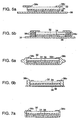
- FIGS. 1A, 1B, and 1C are cross-sectional views of conventional solar cell modules.
- FIG. 1A shows a module with a transparent front support layer 10 of glass or polymer disposed on a transparent encapsulant layer 12.
- the encapsulant layer is disposed on an array of interconnected solar cells 14, which is disposed on a scrim layer 16.
- the scrim layer is disposed on a rear encapsulant layer 18, which is disposed on a backskin 20.
- the backskin 20 may be a Tedlar® laminate of about ten-thousandths of an inch (254 ⁇ m) thickness.
- FIG. 1B shows another module having the same configuration as the module shown in FIG. 1A , except that the backskin 22 is formed of a sheet of glass.
- the assembly shown in FIG. 1A or FIG. 1B is laminated by subjecting the assembly to heat and pressure in a vacuum laminator using a known process.
- the scrim layer 16 is absorbed into the rear encapsulant sheet 18 during lamination and is not therefore shown.
- a perimeter frame 26, typically aluminum, is mounted to surround the edges of the module and a sealing material 28 seals the edges.
- the sealing material 28, in the form of a strip of tape or a caulking type compound, is applied to the edges. Subsequently, sections of the perimeter frame 26 are fastened onto the module and joined together at the corners.
- the color cell roof tile in accordance with the invention features a solar cell module having an improved backskin material which significantly reduces manufacturing costs. This is accomplished by eliminating certain materials which are conventionally used in the construction of prior art modules and by simplifying the steps required to make the module. More particularly, the improved backskin material eliminates the need for a rear encapsulant layer, for a scrim layer, for a sealing strip or sealing material at the module edges, and for the requirement of a perimeter frame of aluminum.
- FIG. 2 shows a solar cell module including the improved backskin material.
- the module 30 includes a front support layer 32 formed of light transmitting material (e.g., glass) and having front and rear surfaces (32s, 32b).
- a transparent encapsulant layer 34 is disposed over the rear surface 32b of the front support layer.
- a first surface 36a of a plurality of interconnected solar cells 36 is disposed over the transparent encapsulant layer 34.
- a flexible backskin layer 38 has a first surface 38a disposed adjacent the second surface 36b of the interconnected solar cells.
- a laminated module is formed by placing the module in a laminator and subjecting it to heat and pressure.
- the lamination process causes the transparent encapsulant layer 34 and the backskin material 38 to melt and bond to the interconnected solar cells 36 and other adjacent surfaces. Once the lamination process is complete, the transparent encapsulant layer 34 and the backskin layer 38, in combination, encapsulate the interconnected solar cells 36.
- the backskin material 38 is a thermoplastic polyolefin including a mixture of at least two ionomers.
- the backskin is a flexible sheet of thermoplastic polyolefin which includes a sodium ionomers, a zinc ionomer, 10-20% glass fibers, and about 5% carbon black and has a thickness of about 0.040 inches (1016 ⁇ m).
- the carbon black is added to provide excellent resistance to weathering effects due to UV sunlight and atmospheric conditions.
- the material 38 combines the features of flexibility, elasticity, strong cohesive bonding to certain surfaces (e.g., glass, metal and polymer), toughness, and excellent resistance to UV light degradation. As a result of these properties and advantages, the use of this material results in significant cost savings in the manufacture of solar cell modules.
- the module can be fitted with a frame.
- a perimeter frame 40 of metallic material can be secured to the module 30.
- a sealant 42 may be applied to the module edges to seal the frame 40 to the module 30.
- the backskin can be wrapped around the edges of the module (see, FIG. 4 ), and the frame heated and bonded directly to the wrapped portion of the backskin material without any adhesive or bonding agent.
- a plurality of mounting brackets are heated and then bonded directly to the backskin material without any adhesive or bonding agent. These aluminum pieces then become slides which allow the module to be slid into place by sliding it along channel brackets (see FIGS. 13-18 ).
- FIG. 4 shows a solar cell module 44 in which portions 46 of the improved backskin material 38 is wrapped around the edges of the assembly and bonds to the solar cells 36, the transparent front encapsulant 34 and the front support layer 32.
- the backskin material 38 provides four functions: (i) the backskin, (ii) the rear encapsulant, (iii) the edge protector, and (iv) the edge sealant.
- the module 44 can be fitted with various types of frames.
- FIGS. 5a-7a show a processing sequence used to form the solar cell module shown in FIG. 4 .
- a sheet of backskin material 38 about one inch (25.4 mm) wider than the cover layer 32 is positioned adjacent the interconnected solar cells 36.
- Narrow strips of the backskin material 38c are laid down along the perimeter of the cover layer 32 with the strips overlapping at the corners.
- the assembly is then placed in a laminator and subjected to heat and pressure with temperatures on the order of 150°C.
- FIG. 6a illustrates the laminated module.
- the backskin 38 and perimeter strips 38c have completely melted together and formed a tight seal along the edge 32c of the front surface of the cover layer 32. Without the need for a mold of any kind, the lamination of a module with the improved backskin yields edge protection and edge sealing. Any excess backskin material can easily be trimmed off to provide the finished module illustrated in FIG. 7a .
- FIGS. 5b-6b show a processing sequence used to form another solar cell module.
- the module is the same as that described in connection with FIG. 5a , except that a plurality of narrow strips of the backskin material 38c are stacked along the perimeter of the cover layer 32.
- the assembly is then placed in a laminator and subjected to heat and pressure.
- FIG. 6b illustrates the laminated module. As shown, the backskin 38 and perimeter strips 38c have completely melted together and formed a tight seal along the front surface of the cover layer 32. With this process, there is no need to trim excess backskin material as describe in connection with FIG. 6a .
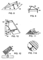
- FIGS. 8-12 illustrate conventional means for mounting modules.
- the solar cell module 50 and the aluminum frame 52 are mounted to metallic mounts 54. These mounts 54 are, in turn, mounted to a metallic structure 56 or to clement.
- the module 50 is connected to a support member 58 which, in turn, is joined to other metal support members 60, 62.
- cross members 64 are mounted to other pieces 66 and directly to a pole 68.
- the module 50 is placed on jacks (or standoffs) 70 which are attached to the roof 72.
- FIG. 12 shows a pole mounting scheme for tracking in which modules 50 are mounted in a metal structure 52 connecting the module frames.
- the solar cell module may include an improved mounting structure.
- a solar cell module 80 includes a front support layer 82, a transparent front encapsulant 84, solar cells 86 and the improved backskin material 88.
- the backskin 88 is wrapped around the edges of the assembly and bonds to the solar cells 86, the transparent front encapsulant 84 and the front support layer 82.
- Extruded mounting brackets 90 which may be aluminum or polymeric material, are heated and bonded directly to rear surface of the backskin material.
- FIG. 14 is a plan view of the module 80 including four mounting brackets 90.
- the module may include two mounting brackets (not shown) extending across the rear surface of the backskin material.
- FIGS. 15 and 17 illustrate two possible configurations of extruded mounting brackets (92, 94).
- the bracket include two C-shaped members (92a, 92b or 94a, 94b) connected by linear member. As described below, these brackets slidably engage a channel bracket for mounting a module.
- the C-shaped members (92a, 92b or 94a, 94b) provide stiffness and permit secure engagement to the channel bracket.
- the linear member is multifunctional in that it allows for various mounting configurations to the channel bracket as explained below (see FIGS. 16 , 19 and 20 ).
- a molded plastic insert (not shown) may be inserted adjacent the linear member and between the C-shaped members. The insert wraps around the bottom and sides of the C-shaped members and engages the channel bracket to accommodate tolerance differences along the channel bracket and C-shaped members.
- FIG. 16 illustrates a module mounted to channel bracket disposed on a structure (e.g., a roof, a pole; or the ground).
- a module 80 includes including a mounting bracket 92 directly mounted to the backskin 88.
- the C-shaped members 92a, 92b slidably engage a channel bracket 96 secured to a structure (not shown). As such, the module 80 can be easily slid along the channel bracket 96 to a desired location.
- FIG. 18 illustrates a module mounting configuration using the mounting bracket 94 shown in FIG. 17 .
- FIGS. 19 and 20 illustrate alternative mounting configurations.
- the module 80 includes including an inverted mounting bracket 92 directly mounted to the backskin 88.
- the C-sbaped members 92a, 92b are secured via a bolt 98 to the channel bracket 96.
- an inverted mounting bracket 94 is secured via a rivet 100 to the channel bracket 96.
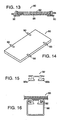
- FIG. 21 illustrates an embodiment in which the electrical leads for the module are coated with a polyolefin material (e.g., polyethylene) or a known blend of rubber and polypropylene.
- the two electrical leads (102a, 102b) are covered with a polyolefin material (101a, 101b) and bonded into the backskin material (103a, 103b).
- the coated leads form an integral seal and no junction box is required on the module.
- FIG. 22 illustrates an embodiment in which the module 104 (see FIG. 4 ) is bonded directly to the exterior surface of an architectural building material 105 (e.g., aluminum, concrete, stone or glass).
- the exterior surface (or the backskin material) is heated and the module is bonded directly to the building material
- the electrical leads (not shown), formed as described in connection with FIG- 21, are brought out through holes 106 in the building material and extend into the interior of the building.
- FIG. 23 shows a solar cell roof tile 108a in accordance with the invention.
- the solar cell roof tile 108a is similar to the solar cell module of FIG. 7a , except that the roof tile 108a includes a border region 107, where a portion of the border region 107a has an extended width for overlapping with an adjacent roof tile.
- the border region 107 is formed by wrapping around a portion of the backskin layer 108b to contact a first surface of the front support layer 109.
- the extended width border region 107a allows the solar cell roof tiles 108a to be overlapped or shingled, while protecting the solar cells 108a and the front support layer 109.
- the front support layer 109 comprises glass, and the interconnected solar cells 110 are encapsulated under the glass 109.
- the overlap region 107a is bonded to the glass 109 in a region where no solar cells 110 are placed.
- the backskin material, with the wrapped around border region allows for greater mechanical stability for the solar cell roof tile over existing solar cell module roof
- the solar cell roof tile 108a has stand-offs 121 molded in the extended width border region 107a.
- the stand-offs 121 prevent movement between overlapping roof tiles 108a and provide vertical spacing between overlapping roof tiles 108a, thereby facilitating air cooling and water runoff.
- FIG. 24 illustrates how two solar cell roof tiles 111, 111' of FIG. 23 can overlap or shingle.
- the extended width border region 107a with the stand-offs 121 of a first roof tile 111' contacts an edge portion of the second surface of the backskin layer 108b of the second roof tile 111.
- a roof tile 111 has a first group of stand-offs 121 formed on the extended width border region 107a and a second group of stand-offs 122 formed the second surface of the backskin layer 108b.
- the second group of stands-offs 122 are placed on the edge portion of the backskin layer 108b and positioned to intersperse between the first group of stand- offs 121' of an adjacent roof tile 111' when they are overlapped.
- FIG. 25a illustrates a solar cell roof tile 130 in which the border region 117 has extensions 119a, 119b.
- the extensions 119a, 119b may be molded onto the roof tile 130.
- Each extension 119a, 119b has a hole for inserting a nail or a screw when mounting the roof tile 130.
- FIG. 25b illustrates a solar cell roof tile 132 in which the overlap region 118 has an extension 120.
- a solar cell roof tile may further include a connector or an electrical lead embedded on a second surface of the backskin layer.
- the roof tile may include a connector having a male portion or a female portion such that when the roof tiles are installed, the male portion of the connector of one roof tile plugs into the female portion of the connector of an adjacent roof tile.
- the roof tile may include an electrical lead which is molded on the second surface of the backskin layer. The ends of the electrical lead are brought out to edges of the roof tile to be accessible. Once the roof tiles are installed, adjacent roof tiles may be interconnected via the electrical leads.
- the stand-offs, the border region with an extended width and the extensions with holes for mounting the solar cell roof tile can all be formed in a single step in the solar cell lamination process.
Landscapes
- Engineering & Computer Science (AREA)
- Architecture (AREA)
- Civil Engineering (AREA)
- Structural Engineering (AREA)
- Physics & Mathematics (AREA)
- Condensed Matter Physics & Semiconductors (AREA)
- Electromagnetism (AREA)
- General Physics & Mathematics (AREA)
- Computer Hardware Design (AREA)
- Microelectronics & Electronic Packaging (AREA)
- Power Engineering (AREA)
- Roof Covering Using Slabs Or Stiff Sheets (AREA)
- Photovoltaic Devices (AREA)
Abstract
Description
- The invention relates to solar cell roof tiles and methods for forming the solar cell roof tiles.
- In general, a solar cell module is formed by interconnecting individual solar cells and laminating the interconnected cells into an integral solar cell module. More specifically, the module usually includes a stiff transparent cover layer made of a polymer or glass material, a transparent front encapsulant which adheres to the cover material and to a plurality of interconnected solar cells, a rear encapsulant which can be transparent or any other color, a stiff backskin for protecting the rear surface of the module, a protective seal which covers the edges of the module, and a perimeter frame made of aluminum which covers the seal. The frame protects the edges of the module when the front cover is made of glass.
- Before the frame is mounted, the module is laminated under heat and pressure. These conditions cause the layers of encapsulant material to melt, bond to adjacent surfaces, and to literally "encapsulate" the solar cells. Since crystalline silicon solar cells are usually brittle, the encapsulant serves to protect the solar cells and reduce breakage when the module is subject to mechanical stress during field usage. After the lamination process, the frame is attached to the module. The frame includes mounting holes which are used to mount the framed module to an object in the field. The mounting process requires screws, bolts, and nuts and can be accomplished in a variety of ways.
- Because costs associated with existing methods for manufacturing solar cell modules tend to be too high, solar electricity is generally not cost-competitive for grid connected applications. For example, three areas in which manufacturing costs need to be reduced include: (i) the materials from which the modules are made; (ii) the labor required to deploy these materials; and (iii) the materials and labor associated with mounting the modules in the field. In particular, the cost of known backskin materials, the cost of the aluminum frame, and the cost of labor required for field mountings in remote areas are known to be too high.
- One known method aimed at reducing solar cell module manufacturing costs includes eliminating the aluminum frame and using a polymeric material as both the backskin and the edging. For amorphous silicon solar cell modules, polymeric frames of a molded thermoplastic material are widely practiced. Reaction injection molding may be used to mold a polyurethane frame around an amorphous silicon module. Reaction injection molding is done in situ (i.e.; on the module), and this is a significant cost savings advantage. However, this molding process has several disadvantages. For example, this process includes the use of a chemical precursor (e.g., isocyanate) which posses environmental hazards. This process also requires a mold, further adding to the overall manufacturing cost. In addition, modules made this way tend to be small (e.g., 5-10 Watt size), not the 50-80 Watt size more generally deployed using aluminum frames. The modules tend to be smaller because of the higher cost of the mold and the limited strength of the resulting polymeric frame with its integral mounting holes. As a result, reaction injection molding is marginally successful in reducing manufacturing costs for amorphous silicon solar cell modules.
- For crystalline silicon modules, the backskin material is generally quite costly. There are two widely used backskin materials, both of which tend to be expensive. The most popular material used is a Tedlar® /polyester/ethylene vinyl acetate laminate, and the other widely used backskin material is glass. Two additional layers of material are often deployed between the solar cells in the module and the backskin, further adding to the manufacturing costs. A rear sheet of the same material as the transparent encapsulant, (e.g., Ethylene Vinyl Acetate) and a sheet of "scrim," which allows for efficient air removal during vacuum lamination, must be applied over the cells before the backskin material is deployed.
- Both amorphous and crystalline silicon modules also include a junction box which is mounted onto the backskin material and from which all external electrical connections are made. Further labor is required to make connections to the junction box.
- A frame, along with an elastomeric edging material, is often used when the front support for the module is formed of tempered glass. This construction protects the edges, as the tempered glass is vulnerable to breakage if an edge is damaged. While the use of a frame adds durability to the solar cell module, it also adds significantly to the manufacturing costs.
- The labor intensive process of mounting the module can add significantly to the overall cost of solar electricity. Modules are mounted by assembling screws, nuts, and bolts to the appropriate mounting holes on the aluminum frame- However, solar cell modules are often located in remote areas which have no other source of electricity- As such, the mounting process often involves attaching the hardware in difficult, awkward and not readily accessible locations such as on rugged terrain, or roof tops. Therefore a need exists for a low-cost solar cell module that can be used as a roof tele.
- The foregoing discussion demonstrates that the manufacture of solar cell modules tends to be too costly and involves too much labor to allow for the realization of the goal of cost-competitive solar electricity for wide-scale global use.
- An example of a conventional solar cell roofing tile and method for its manufacture may be found, for example, in
DE3247469 A1 . This discloses a roofing tile having a supporting translucent base member for overlapping covering of sloping roof surfaces, wherein semiconductor photovoltaic cells are attached to the underside of in the area thereof not covered by adjacent roofing tiles, characterised in that the space underneath the roofing tiles serves as an ascending air channel for cooling the roofing tiles and the semiconductor photovoltaic cells. - Another example of a known manufacturing method for encapsulation of solar cell elements within roof tiles may be found, for example, in
JP 09-045947 - The invention provides a solar cell roof tile as claimed in claim 1 and a method for its manufacture as claimed in
claim 12. - The roof tile in accordance with the invention features a solar cell module with a backskin material which provides all of the following advantageous features: (i) a strong and weatherable backing for the module; (ii) an edging which can (optionally) eliminate the need for an aluminum frame; (iii) an edge Seal that eliminates the need for any additional seal materials; (iv) a rear encapsulant that eliminates the need for a separate rear sheet of encapsulant material; and (v) the elimination of the need for a scrim layer to remove air during lamination. The backskin material is easily formed and molded in situ during the module manufacturing process. The primary advantages of solar cell modules utilizing the backskin material include a significant reduction in manufacturing costs and module mounting costs.
- The backskin material is a thermoplastic olefin which may be composed of two different kinds of ionomer, mineral filler and a pigment. Ionomer is a generic name which herein refers to either a co-polymer of ethylene and methacrylic acid or acrylic acid, which has been neutralized with the addition of a salt which supplies a cation such as Na+, Li+, , Zn+-r, Al+++, Mg++, etc., or a co-polymer of polyethylene and an acrylate to which cations such as those listed above have been added. The material has the usual covalent bonds which polymers typically have, but also has regions of ionic bonding. The latter imparts to the materials a built-in cross linking lonomers are characterized as being tough and weatherable polymers. The combination of two ionomers produces a known synergistic effect which improves the water vapor barrier properties of the material over and above the barrier properties of either of the individual ionomer components.
- The addition of a mineral filler, such as glass fiber, to the backskin material provides for a lower coefficient of thermal expansion. This is important for preserving strong, long, lasting bonds to all the adjacent surfaces in a module which undergoes ambient temperature extremes. The glass fibers also improve the water vapor and oxygen barrier properties of the material and increase the flexural modulus three or four times over the ionomers themselves. This makes the backskin material very strong, but still flexible. A pigment, such as carbon black, is added to the backskin material to provide excellent weathering properties (i.e. resistance to the degradation from the UV light in the solar spectrum).
- The solar cell module may be laminated. The module includes a front support layer formed of light transmitting material, such as glass, and having first and second surfaces. A transparent encapsulant layer, formed of at least one ionomer, is disposed adjacent the second surface of the front support layer. A first surface of a plurality of interconnected solar cells are disposed adjacent the transparent encapsulant layer. A backskin layer, formed of a thermoplastic olefin, has a first surface disposed adjacent a second surface of the interconnected solar cells. The transparent encapsulant layer and the backskin layer, in combination, encapsulate the interconnected solar cells.
- A portion of the backskin layer is wrapped around at least one edge of the module for contacting the first surface of the front support layer, to thereby form an edge seal. The presence of acid functionality in the ionomers utilized in the backskin material yields the property of bonding cohesively, not merely adhesively, to various materials including glass, metals, and other polymers. This property is utilized to provide a wraparound backskin that also serves as an edge seal without the need for additional adhesive materials. An optional metallic frame may be securely disposed to at least one edge of the module.
- A method of manufacturing a solar cell module is described as follows. A front support layer is formed of light transmitting material (eg., glass). A transparent encapsulant layer, formed of at least one ionomer, is placed adjacent a second surface of the front support layer. A plurality of interconnected solar cells having first and second surfaces are positioned adjacent the transparent encapsulant layer. A backskin layer formed of thermoplastic olefin is placed adjacent a second surface of the interconnected solar cells to thereby form an assembly. The assembly is laminated to form the solar cell module. More specifically, the assembly is subjected to heat and pressure to encapsulate the interconnected solar cells with the encapsulant layer and the backskin layer.
- A portion of the backskin layer is wrapped around at least one edge of the assembly for contacting the first surface of the front support layer to form an edge seal. Also, a metallic frame may be secured adjacent at least one edge of the module.
- In another aspect, the electrical leads for the module are coated with a polyolefin material (e.g., polyethylene) or a known blend of rubber and polypropylene. The polyolefin coated leads can be heated and bonded into the backskin material to form an integral seal. This embodiment (i) provides a superior approach for bringing the leads out of the module, (ii) eliminates the ingress of moisture, and (iii) eliminates the need for a junction box entirety.
- In yet another aspect, a solar cell module employing the above-described backskin material is bonded directly to the exterior surface of an architectural building material (e.g., aluminum, concrete, stone or glass). The above-described electrical leads can be brought out through holes in the building material.
- The invention features a solar cell roof tile. The roof tile includes a front support layer, a transparent encapsulant layer, a plurality of interconnected solar cells and a backskin layer. The front support layer is formed of light transmitting material and has first and second surfaces. The transparent encapsulant layer is disposed adjacent the second surface of the front support layer. The interconnected solar cells have a first surface disposed adjacent the transparent encapsulant layer. The backskin layer has a first surface disposed adjacent a second surface of the interconnected solar cells, wherein a portion of the backskin layer wraps around and contacts the first surface of the front support layer to form the border region. A portion of the border region has an extended width. The solar cell roof tile may have stand-offs disposed on the extended width border region for providing vertical spacing with respect to an adjacent solar cell roof tile.
- In another aspect, the invention features a method of manufacturing a solar cell roof tile. According to the method, a front support layer formed of light transmitting material is provided. A, transparent encapsulant layer is placed adjacent a second surface of the front support layer. A plurality of interconnected solar cells are positioned adjacent the transparent encapsulant layer. A backskin layer is placed adjacent a second surface of the interconnected solar cells. A border region is formed by wrapping a portion of the backskin layer around to contact the first surface of the front support layer. A portion of the border region has an extended width. An assembly of the front support layer, the transparent encapsulant layer, the interconnected solar cells and the backskin layer is laminated to form the solar cell roof tile. In one embodiment, stand-offs are disposed on the extended width border region for providing vertical spacing with respect to an adjacent solar cell roof tile.
-
-
FIG. 1A is a cross-sectional view of a conventional solar cell module with a Tedlar® laminate backskin. -
FIG. 1B is a cross-sectional view of a conventional module with a glass backskin. -
FIG. 1C is a cross-sectional view of a conventional module with a perimeter aluminum frame. -
FIG. 2 is a cross-sectional view of a solar cell module with the improved backskin material of the invention. -
FIG. 3 is a cross-sectional view of a solar cell module with the improved backskin material of the invention and mounted in a perimeter aluminum frame using a sealant. -
FIG. 4 is a cross-sectional view of a solar cell module with the improved backskin material wrapped around the assembly to form an edge seal. -
FIGS. 5a-7a are a series of cross-sectional views of a lamination process for a solar cell with edge seal and edge protection components. -
FIG. 5b-6b are series of cross-sectional views of another lamination process for a solar cell with edge seal and edge protection components. -
FIG. 8 illustrates a conventional ground mounting method of a solar cell module. -
FIG. 9 illustrates another conventional ground mounting method of a solar cell module. -
FIG. 10 illustrates a conventional pole mounting method of a solar cell module. -
FIG. 11 and 11A illustrate a conventional roof mounting method of a solar cell module. -
FIG. 12 illustrates a conventional solar cell mounting method which includes ground mounted pole and one axis tracking. -
FIG. 13 is a cross-sectional view of a solar cell module of IG. 7a, modified to include mounting bracket bonded to the backskin material. -
FIG. 14 is a rear view of the solar cell module ofFIG. 13 . -
FIG. 15 is a cross-sectional view of an extruded mounting bracket. -
FIG. 16 is a cross-sectional view of the mounting bracket ofFIG. 15 slidably engaging a channel bracket. -
FIG. 17 is a cross-sectional view of an alternative extruded mounting bracket. -
FIG. 18 is a cross-sectional view of the mounting bracket ofFIG. 17 slidably engaging a channel bracket. -
FIG. 19 is a cross-sectional view of the mounting bracket ofFIG. 17 slidably engaging a channel bracket using a bolt. -
FIG. 20 is a cross-sectional view of the mounting bracket of FTG. 17 slidably engaging a channel bracket using a rivet. -
FIG. 21 is an illustration of a solar cell module with polyolefin covered leads bonded directly to the backskin. -
FIG. 22 is an illustration of the module ofFIG. 4 bonded directly to the outer surface of an architectural building material. -
FIG. 23 is an illustration of a solar cell roof tile in accordance with the invention. -
FIG. 24 is an illustration of two solar cell roof tiles in accordance with the invention overlapping each other. -
FIG. 25a is an illustration of extensions molded onto the solar cell roof tile in accordance with the invention. -
FIG. 25b is an illustration of an extension molded onto the solar cell roof tile in accordance with the invention. -
FIGS. 1A, 1B, and 1C are cross-sectional views of conventional solar cell modules.FIG. 1A shows a module with a transparentfront support layer 10 of glass or polymer disposed on atransparent encapsulant layer 12. The encapsulant layer is disposed on an array of interconnectedsolar cells 14, which is disposed on ascrim layer 16. The scrim layer is disposed on arear encapsulant layer 18, which is disposed on abackskin 20. Thebackskin 20 may be a Tedlar® laminate of about ten-thousandths of an inch (254µm) thickness.FIG. 1B shows another module having the same configuration as the module shown inFIG. 1A , except that thebackskin 22 is formed of a sheet of glass. The assembly shown inFIG. 1A or FIG. 1B is laminated by subjecting the assembly to heat and pressure in a vacuum laminator using a known process. - Referring to
FIG. 1C , thescrim layer 16 is absorbed into therear encapsulant sheet 18 during lamination and is not therefore shown. Aperimeter frame 26, typically aluminum, is mounted to surround the edges of the module and a sealingmaterial 28 seals the edges. The sealingmaterial 28, in the form of a strip of tape or a caulking type compound, is applied to the edges. Subsequently, sections of theperimeter frame 26 are fastened onto the module and joined together at the corners. - The color cell roof tile in accordance with the invention features a solar cell module having an improved backskin material which significantly reduces manufacturing costs. This is accomplished by eliminating certain materials which are conventionally used in the construction of prior art modules and by simplifying the steps required to make the module. More particularly, the improved backskin material eliminates the need for a rear encapsulant layer, for a scrim layer, for a sealing strip or sealing material at the module edges, and for the requirement of a perimeter frame of aluminum.
-
FIG. 2 shows a solar cell module including the improved backskin material. Themodule 30 includes afront support layer 32 formed of light transmitting material (e.g., glass) and having front and rear surfaces (32s, 32b). Atransparent encapsulant layer 34 is disposed over therear surface 32b of the front support layer. Afirst surface 36a of a plurality of interconnectedsolar cells 36 is disposed over thetransparent encapsulant layer 34. Aflexible backskin layer 38 has afirst surface 38a disposed adjacent thesecond surface 36b of the interconnected solar cells. A laminated module is formed by placing the module in a laminator and subjecting it to heat and pressure. The lamination process causes thetransparent encapsulant layer 34 and thebackskin material 38 to melt and bond to the interconnectedsolar cells 36 and other adjacent surfaces. Once the lamination process is complete, thetransparent encapsulant layer 34 and thebackskin layer 38, in combination, encapsulate the interconnectedsolar cells 36. - In accordance with the invention, the
backskin material 38 is a thermoplastic polyolefin including a mixture of at least two ionomers. In one detailed embodiment, the backskin is a flexible sheet of thermoplastic polyolefin which includes a sodium ionomers, a zinc ionomer, 10-20% glass fibers, and about 5% carbon black and has a thickness of about 0.040 inches (1016 µm). The carbon black is added to provide excellent resistance to weathering effects due to UV sunlight and atmospheric conditions. Thus, thematerial 38 combines the features of flexibility, elasticity, strong cohesive bonding to certain surfaces (e.g., glass, metal and polymer), toughness, and excellent resistance to UV light degradation. As a result of these properties and advantages, the use of this material results in significant cost savings in the manufacture of solar cell modules. - Referring to
FIG. 3 , the module can be fitted with a frame. In one embodiment, aperimeter frame 40 of metallic material can be secured to themodule 30. Asealant 42 may be applied to the module edges to seal theframe 40 to themodule 30. Alternatively, the backskin can be wrapped around the edges of the module (see,FIG. 4 ), and the frame heated and bonded directly to the wrapped portion of the backskin material without any adhesive or bonding agent. In another embodiment, instead of using a perimeter frame, a plurality of mounting brackets are heated and then bonded directly to the backskin material without any adhesive or bonding agent. These aluminum pieces then become slides which allow the module to be slid into place by sliding it along channel brackets (seeFIGS. 13-18 ). -
FIG. 4 shows asolar cell module 44 in whichportions 46 of theimproved backskin material 38 is wrapped around the edges of the assembly and bonds to thesolar cells 36, the transparentfront encapsulant 34 and thefront support layer 32. In this configuration, thebackskin material 38 provides four functions: (i) the backskin, (ii) the rear encapsulant, (iii) the edge protector, and (iv) the edge sealant. As noted previously, themodule 44 can be fitted with various types of frames. -
FIGS. 5a-7a show a processing sequence used to form the solar cell module shown inFIG. 4 . Referring toFIG. 5a , a sheet ofbackskin material 38 about one inch (25.4 mm) wider than thecover layer 32 is positioned adjacent the interconnectedsolar cells 36. Narrow strips of thebackskin material 38c are laid down along the perimeter of thecover layer 32 with the strips overlapping at the corners. The assembly is then placed in a laminator and subjected to heat and pressure with temperatures on the order of 150°C.FIG. 6a illustrates the laminated module. As shown, thebackskin 38 and perimeter strips 38c have completely melted together and formed a tight seal along theedge 32c of the front surface of thecover layer 32. Without the need for a mold of any kind, the lamination of a module with the improved backskin yields edge protection and edge sealing. Any excess backskin material can easily be trimmed off to provide the finished module illustrated inFIG. 7a . -
FIGS. 5b-6b show a processing sequence used to form another solar cell module. Referring toFIG. 5b , the module is the same as that described in connection withFIG. 5a , except that a plurality of narrow strips of thebackskin material 38c are stacked along the perimeter of thecover layer 32. The assembly is then placed in a laminator and subjected to heat and pressure.FIG. 6b illustrates the laminated module. As shown, thebackskin 38 and perimeter strips 38c have completely melted together and formed a tight seal along the front surface of thecover layer 32. With this process, there is no need to trim excess backskin material as describe in connection withFIG. 6a . -
FIGS. 8-12 illustrate conventional means for mounting modules. InFIG. 8 , thesolar cell module 50 and thealuminum frame 52 are mounted to metallic mounts 54. These mounts 54 are, in turn, mounted to ametallic structure 56 or to clement. InFIG. 9 , themodule 50 is connected to asupport member 58 which, in turn, is joined to othermetal support members FIG. 10 ,cross members 64 are mounted toother pieces 66 and directly to apole 68. InFIG. 11 and 11A , themodule 50 is placed on jacks (or standoffs) 70 which are attached to theroof 72.FIG. 12 shows a pole mounting scheme for tracking in whichmodules 50 are mounted in ametal structure 52 connecting the module frames. - The solar cell module may include an improved mounting structure. Referring to
FIG. 13 , asolar cell module 80 includes afront support layer 82, a transparentfront encapsulant 84,solar cells 86 and theimproved backskin material 88. As shown, thebackskin 88 is wrapped around the edges of the assembly and bonds to thesolar cells 86, the transparentfront encapsulant 84 and thefront support layer 82. Extruded mountingbrackets 90, which may be aluminum or polymeric material, are heated and bonded directly to rear surface of the backskin material.FIG. 14 is a plan view of themodule 80 including four mountingbrackets 90. In another embodiment, the module may include two mounting brackets (not shown) extending across the rear surface of the backskin material. -
FIGS. 15 and17 illustrate two possible configurations of extruded mounting brackets (92, 94). In both configurations, the bracket include two C-shaped members (92a, 92b or 94a, 94b) connected by linear member. As described below, these brackets slidably engage a channel bracket for mounting a module. The C-shaped members (92a, 92b or 94a, 94b) provide stiffness and permit secure engagement to the channel bracket. The linear member is multifunctional in that it allows for various mounting configurations to the channel bracket as explained below (seeFIGS. 16 ,19 and 20 ). Also, a molded plastic insert (not shown) may be inserted adjacent the linear member and between the C-shaped members. The insert wraps around the bottom and sides of the C-shaped members and engages the channel bracket to accommodate tolerance differences along the channel bracket and C-shaped members. -
FIG. 16 illustrates a module mounted to channel bracket disposed on a structure (e.g., a roof, a pole; or the ground). Amodule 80 includes including a mountingbracket 92 directly mounted to thebackskin 88. The C-shapedmembers channel bracket 96 secured to a structure (not shown). As such, themodule 80 can be easily slid along thechannel bracket 96 to a desired location.FIG. 18 illustrates a module mounting configuration using the mountingbracket 94 shown inFIG. 17 . -
FIGS. 19 and 20 illustrate alternative mounting configurations. InFIG. 19 , themodule 80 includes including an inverted mountingbracket 92 directly mounted to thebackskin 88. The C-sbaped members bolt 98 to thechannel bracket 96. InFIG. 20 , an inverted mountingbracket 94 is secured via arivet 100 to thechannel bracket 96. -
FIG. 21 illustrates an embodiment in which the electrical leads for the module are coated with a polyolefin material (e.g., polyethylene) or a known blend of rubber and polypropylene. The two electrical leads (102a, 102b) are covered with a polyolefin material (101a, 101b) and bonded into the backskin material (103a, 103b). As such, the coated leads form an integral seal and no junction box is required on the module. -
FIG. 22 illustrates an embodiment in which the module 104 (seeFIG. 4 ) is bonded directly to the exterior surface of an architectural building material 105 (e.g., aluminum, concrete, stone or glass). The exterior surface (or the backskin material) is heated and the module is bonded directly to the building material The electrical leads (not shown), formed as described in connection with FIG- 21, are brought out throughholes 106 in the building material and extend into the interior of the building. -
FIG. 23 shows a solarcell roof tile 108a in accordance with the invention. The solarcell roof tile 108a is similar to the solar cell module ofFIG. 7a , except that theroof tile 108a includes aborder region 107, where a portion of theborder region 107a has an extended width for overlapping with an adjacent roof tile. Theborder region 107 is formed by wrapping around a portion of thebackskin layer 108b to contact a first surface of thefront support layer 109. The extendedwidth border region 107a allows the solarcell roof tiles 108a to be overlapped or shingled, while protecting thesolar cells 108a and thefront support layer 109. In one embodiment, thefront support layer 109 comprises glass, and the interconnectedsolar cells 110 are encapsulated under theglass 109. Theoverlap region 107a is bonded to theglass 109 in a region where nosolar cells 110 are placed. The backskin material, with the wrapped around border region, allows for greater mechanical stability for the solar cell roof tile over existing solar cell module roof tile designs. - In one embodiment, the solar
cell roof tile 108a has stand-offs 121 molded in the extendedwidth border region 107a. The stand-offs 121 prevent movement between overlappingroof tiles 108a and provide vertical spacing between overlappingroof tiles 108a, thereby facilitating air cooling and water runoff. -
FIG. 24 illustrates how two solarcell roof tiles 111, 111' ofFIG. 23 can overlap or shingle. The extendedwidth border region 107a with the stand-offs 121 of a first roof tile 111' contacts an edge portion of the second surface of thebackskin layer 108b of thesecond roof tile 111. In one embodiment, aroof tile 111 has a first group of stand-offs 121 formed on the extendedwidth border region 107a and a second group of stand-offs 122 formed the second surface of thebackskin layer 108b. The second group of stands-offs 122 are placed on the edge portion of thebackskin layer 108b and positioned to intersperse between the first group of stand- offs 121' of an adjacent roof tile 111' when they are overlapped. -
FIG. 25a illustrates a solarcell roof tile 130 in which theborder region 117 hasextensions extensions roof tile 130. Eachextension roof tile 130.FIG. 25b illustrates a solarcell roof tile 132 in which theoverlap region 118 has anextension 120. - A solar cell roof tile may further include a connector or an electrical lead embedded on a second surface of the backskin layer. The roof tile may include a connector having a male portion or a female portion such that when the roof tiles are installed, the male portion of the connector of one roof tile plugs into the female portion of the connector of an adjacent roof tile. The roof tile may include an electrical lead which is molded on the second surface of the backskin layer. The ends of the electrical lead are brought out to edges of the roof tile to be accessible. Once the roof tiles are installed, adjacent roof tiles may be interconnected via the electrical leads.
- It should be stressed that the stand-offs, the border region with an extended width and the extensions with holes for mounting the solar cell roof tile can all be formed in a single step in the solar cell lamination process.
Claims (18)
- A solar cell roof tile (108a - Figure 23) comprising:a front support layer (32 - Figure 2; 109 - Figure 23) formed of light transmitting material and having first and second surfaces (32a, 32b - Figure 2);a transparent encapsulant layer (34 - Figure 2) disposed adjacent the second surface (32b - Figure 2) of the front support layer;a plurality of interconnected solar cells (36 - Figure 2; 110 - Figure 23) having a first surface (36a - Figure 2) disposed adjacent the transparent encapsulant layer; anda backskin layer (38 - Figure 2; 108b - Figure 23) having a first surface (38a - Figure 2) disposed adjacent a second surface (36b - Figure 2) of the interconnected solar cells, wherein a portion of the backskin layer wraps around and contacts the first surface (32a - Figure 2) of the front support layer to form the border region (107 - Figure 23), a portion of the border region (107a - Figure 23) having an extended width.
- The solar cell roof tile of claim 1 further comprising a plurality of stand-offs (121 - Figure 23) disposed on the border region having an extended width for providing vertical spacing with respect to an adjacent solar cell roof tile.
- The solar cell roof tile of claim 1 further comprising a first group of stand-offs (121 - Figure 24) disposed on the border region having an extended width and a second group of stand-offs (122 - Figure 24) disposed on a second surface of the backskin layer, wherein the first group of stand-offs of a solar cell roof tile is designed to intersperse between the second group of stand-offs of an adjacent solar cell roof tile.
- The solar cell roof tile of claim 1 wherein the border region has an extension (119a, 119b - Figure 25a; 120 - Figure 25b) defining a hole.
- The solar cell roof tile of claim 1 wherein the backskin layer is formed of thermoplastic olefin.
- The solar cell roof tile of claim 5 wherein the thermoplastic olefin comprises a first ionomer and a second ionomer.
- The solar cell roof tile of claim 1 wherein the backskin layer is flexible.
- The solar cell roof tile of claim 1 wherein the front support layer comprises glass.
- The solar cell roof tile of claim 1 wherein the transparent encapsulant layer comprises at least one ionomer.
- The solar cell roof tile of claim 1 further comprising an electrical lead embedded on a second surface (38b - Figure 2) of the backskin layer.
- The solar cell roof tile of claim 1 further comprising a connector embedded on a second surface (38b Figure 2) of the backskin layer.
- A method of manufacturing a solar cell roof tile (108a - Figure 23) comprising:providing a front support layer (32 - Figure 2; 109 - Figure 23) formed of light transmitting material and having first and second surfaces (32a, 32b - Figure 2);placing a transparent encapsulant layer (34 - Figure 2) adjacent the second surface (32b - Figure 2) of the front support layer;positioning a plurality of interconnected solar cells (36 - Figure 2; 110 - Figure 23) having first and second surfaces (36a, 36b - Figure 2) adjacent the transparent encapsulant layer;placing a backskin layer (38 - Figure 2; 108b - Figure 23) adjacent a second surface (36b - Figure 2) of the interconnected solar cells;forming a border region (107 - Figure 23) by wrapping a portion of the backskin layer around to contact the first surface (32a - Figure 2) of the front support layer, where a portion of the border region (107a - Figure 23) has an extended width; andlaminating an assembly of the front support layer, the transparent encapsulant layer, the interconnected solar cells and the backskin layer to form the roof tile.
- The method of claim 12 wherein the laminating step comprises subjecting the assembly to heat and pressure to encapsulate the interconnected solar cells with the encapsulant layer and the backskin layer.
- The method of claim 12 further comprising molding a plurality of stand-offs (121 - Figure 23) in the border region having an extended width for providing vertical spacing with respect to an adjacent solar cell roof tile.
- The method of claim 12 further comprising molding a first group of stand-offs (121 - Figure 24) in the border region having an extended width and a second group of stand-offs (122 - Figure 24) in a second surface of the backskin layer, wherein the second group of stand-offs are positioned to intersperse between the first group of stand-offs of an adjacent roof tile.
- The method of claim 12 wherein the border region has an extension (119a, 119b - Figure 25a; 120 - Figure 25b) defining a hole.
- The method of claim 12 further comprising embedding a connector on a second surface (38b - Figure 2) of the backskin layer.
- The method of claim 12 further comprising embedding an electrical lead on a second surface (38b - Figure 2) of the backskin layer.
Applications Claiming Priority (3)
| Application Number | Priority Date | Filing Date | Title |
|---|---|---|---|
| US08/964,368 US5986203A (en) | 1996-06-27 | 1997-11-04 | Solar cell roof tile and method of forming same |
| US964368 | 1997-11-04 | ||
| PCT/US1998/023450 WO1999023706A1 (en) | 1997-11-04 | 1998-11-04 | Solar cell roof tile and method of forming same |
Publications (2)
| Publication Number | Publication Date |
|---|---|
| EP1029367A1 EP1029367A1 (en) | 2000-08-23 |
| EP1029367B1 true EP1029367B1 (en) | 2009-05-06 |
Family
ID=25508465
Family Applications (1)
| Application Number | Title | Priority Date | Filing Date |
|---|---|---|---|
| EP98956545A Expired - Lifetime EP1029367B1 (en) | 1997-11-04 | 1998-11-04 | Solar cell roof tile and method of forming same |
Country Status (7)
| Country | Link |
|---|---|
| US (1) | US5986203A (en) |
| EP (1) | EP1029367B1 (en) |
| JP (1) | JP2001522147A (en) |
| AU (1) | AU1304599A (en) |
| DE (1) | DE69840814D1 (en) |
| ES (1) | ES2326291T3 (en) |
| WO (1) | WO1999023706A1 (en) |
Families Citing this family (168)
| Publication number | Priority date | Publication date | Assignee | Title |
|---|---|---|---|---|
| JPH11289103A (en) * | 1998-02-05 | 1999-10-19 | Canon Inc | Semiconductor device and solar cell module and their overhauling methods |
| US20100108118A1 (en) * | 2008-06-02 | 2010-05-06 | Daniel Luch | Photovoltaic power farm structure and installation |
| US8664030B2 (en) | 1999-03-30 | 2014-03-04 | Daniel Luch | Collector grid and interconnect structures for photovoltaic arrays and modules |
| US20090293941A1 (en) * | 2008-06-02 | 2009-12-03 | Daniel Luch | Photovoltaic power farm structure and installation |
| EP1071137A3 (en) * | 1999-07-21 | 2007-03-21 | Kaneka Corporation | Roofing tile having photovoltaic module to generate power |
| DE60032292T2 (en) * | 1999-07-23 | 2007-07-12 | Sanyo Electric Co., Ltd., Moriguchi | Arrangement for generating electrical energy from solar energy |
| ES2153796B1 (en) * | 1999-08-24 | 2001-10-01 | Fritta S L | PHOTOVOLTAIC ENERGY GENERATOR COATING. |
| AU6704600A (en) * | 1999-08-24 | 2001-03-19 | Fritta, S.L. | Photovoltaic energy generator coating |
| PT1244649E (en) * | 1999-12-23 | 2005-06-30 | Icos Corp | PHOSPHODIESTERASE INHIBITORS SPECIFIC MFA CYCLIC |
| US6362213B1 (en) | 1999-12-23 | 2002-03-26 | Icos Corporation | Cyclic AMP-specific phosphodiesterase inhibitors |
| JP3594540B2 (en) * | 2000-09-11 | 2004-12-02 | 三洋電機株式会社 | Solar cell module |
| DE20110459U1 (en) * | 2001-06-25 | 2001-09-20 | Osmer Klaus Dieter | Mounting system for framed solar modules |
| US7001455B2 (en) * | 2001-08-10 | 2006-02-21 | Evergreen Solar, Inc. | Method and apparatus for doping semiconductors |
| US7267721B2 (en) * | 2001-09-19 | 2007-09-11 | Evergreen Solar, Inc. | Method for preparing group IV nanocrystals with chemically accessible surfaces |
| WO2003025260A1 (en) * | 2001-09-19 | 2003-03-27 | Evergreen Solar, Inc. | High yield method for preparing silicon nanocrystals with chemically accessible surfaces |
| AUPS038702A0 (en) * | 2002-02-08 | 2002-02-28 | Sustainable Technologies International | Construction products with integrated photovoltaics |
| US6883290B2 (en) | 2002-02-20 | 2005-04-26 | Powerlight Corporation | Shingle system and method |
| US20030154667A1 (en) * | 2002-02-20 | 2003-08-21 | Dinwoodie Thomas L. | Shingle system |
| US7178295B2 (en) | 2002-02-20 | 2007-02-20 | Powerlight Corporation | Shingle assembly |
| US7578102B2 (en) * | 2002-08-16 | 2009-08-25 | Mark Banister | Electric tile modules |
| US20040139689A1 (en) * | 2003-01-21 | 2004-07-22 | Sunlit Systems | Novel Low Cost Implementation of a High Efficiency Solar Electric System using existing Building Structures |
| US7793467B1 (en) | 2003-01-31 | 2010-09-14 | Melton David S | Passively cooled and heated electrical components and power building |
| US7531741B1 (en) | 2003-03-07 | 2009-05-12 | Sacred Power Corporation | Tracking solar shelter |
| DE10340746A1 (en) * | 2003-09-01 | 2005-03-31 | Decoma (Germany) Gmbh | Roof box device, and roof module with integrated roof box device |
| WO2005045942A1 (en) * | 2003-11-06 | 2005-05-19 | Firac International Co., Ltd. | Solar tile and its laying method |
| CA2487774C (en) * | 2003-11-19 | 2012-10-30 | Elk Premium Building Products, Inc. | Photovoltaic building materials and related methods of installation |
| US20050166383A1 (en) * | 2004-01-31 | 2005-08-04 | Dean Newberry | Roof jack |
| US8344239B2 (en) * | 2004-02-13 | 2013-01-01 | Pvt Solar, Inc. | Mechanism for mounting solar modules |
| US7856769B2 (en) * | 2004-02-13 | 2010-12-28 | Pvt Solar, Inc. | Rack assembly for mounting solar modules |
| EP1601022A1 (en) * | 2004-05-28 | 2005-11-30 | Hilber Technic Cooperation GmbH | Solar installation |
| US7902452B2 (en) | 2004-06-17 | 2011-03-08 | E. I. Du Pont De Nemours And Company | Multilayer ionomer films for use as encapsulant layers for photovoltaic cell modules |
| US7531733B2 (en) * | 2004-06-21 | 2009-05-12 | Mark David Steele | Electronic drum pedal |
| US20090038668A1 (en) * | 2007-08-08 | 2009-02-12 | Joshua Reed Plaisted | Topologies, systems and methods for control of solar energy supply systems |
| EP1703037B1 (en) * | 2005-02-24 | 2008-01-02 | 3S Swiss Solar Systems AG | Roof or wall covering |
| US20060225776A1 (en) * | 2005-04-08 | 2006-10-12 | Portable Pipe Hangers, Inc. | Skylight solar panel assembly |
| US20070193618A1 (en) * | 2005-09-19 | 2007-08-23 | Solar Roofing Systems, Inc. | Integrated Solar Roofing System |
| US20090090412A1 (en) * | 2005-12-22 | 2009-04-09 | Hermann Calwer | Photovoltaic device and method for encapsulating |
| US7572334B2 (en) | 2006-01-03 | 2009-08-11 | Applied Materials, Inc. | Apparatus for fabricating large-surface area polycrystalline silicon sheets for solar cell application |
| DE102006009412A1 (en) * | 2006-02-23 | 2007-08-30 | Zentrum für Sonnenenergie- und Wasserstoff-Forschung Baden-Württemberg | Solar modular system has self-supporting support structure, support profile with lateral inserted profile for laterally adding an additional support profile or connecting profile or terminal profile and heat dissipation structure |
| US7884279B2 (en) * | 2006-03-16 | 2011-02-08 | United Technologies Corporation | Solar tracker |
| US9236512B2 (en) | 2006-04-13 | 2016-01-12 | Daniel Luch | Collector grid and interconnect structures for photovoltaic arrays and modules |
| US9865758B2 (en) | 2006-04-13 | 2018-01-09 | Daniel Luch | Collector grid and interconnect structures for photovoltaic arrays and modules |
| US8729385B2 (en) | 2006-04-13 | 2014-05-20 | Daniel Luch | Collector grid and interconnect structures for photovoltaic arrays and modules |
| US8884155B2 (en) | 2006-04-13 | 2014-11-11 | Daniel Luch | Collector grid and interconnect structures for photovoltaic arrays and modules |
| US9006563B2 (en) | 2006-04-13 | 2015-04-14 | Solannex, Inc. | Collector grid and interconnect structures for photovoltaic arrays and modules |
| US8822810B2 (en) | 2006-04-13 | 2014-09-02 | Daniel Luch | Collector grid and interconnect structures for photovoltaic arrays and modules |
| EP2033239A4 (en) * | 2006-05-18 | 2014-01-08 | Pvt Solar Inc | Interconnected solar module design and system |
| US20080035140A1 (en) * | 2006-05-26 | 2008-02-14 | Bp Corporation North America Inc. | Solar Roof Tile |
| DE102006027629B4 (en) * | 2006-06-13 | 2013-10-17 | Willi Bihler | Solar element with tempering device, method of manufacture, kit, use for a solar energy system and solar energy system |
| JP2009542010A (en) * | 2006-06-21 | 2009-11-26 | エバーグリーン ソーラー, インコーポレイテッド | Photovoltaic module without frame |
| US7851694B2 (en) * | 2006-07-21 | 2010-12-14 | E. I. Du Pont De Nemours And Company | Embossed high modulus encapsulant sheets for solar cells |
| US8772624B2 (en) * | 2006-07-28 | 2014-07-08 | E I Du Pont De Nemours And Company | Solar cell encapsulant layers with enhanced stability and adhesion |
| US7847184B2 (en) | 2006-07-28 | 2010-12-07 | E. I. Du Pont De Nemours And Company | Low modulus solar cell encapsulant sheets with enhanced stability and adhesion |
| WO2008028151A2 (en) * | 2006-08-31 | 2008-03-06 | Pvt Solar, Inc. | Technique for electrically bonding solar modules and mounting assemblies |
| US7721492B2 (en) * | 2006-09-06 | 2010-05-25 | Pvt Solar, Inc. | Strut runner member and assembly using same for mounting arrays on rooftops and other structures |
| US8581094B2 (en) * | 2006-09-20 | 2013-11-12 | Dow Global Technologies, Llc | Electronic device module comprising polyolefin copolymer |
| BRPI0715034B1 (en) * | 2006-09-20 | 2019-05-14 | Dow Global Technologies Inc. | ELECTRONIC DEVICE MODULE |
| US20080115825A1 (en) * | 2006-09-20 | 2008-05-22 | Patel Rajen M | Electronic Device Module Comprising an Ethylene Multi-Block Copolymer |
| US7857269B2 (en) * | 2006-11-29 | 2010-12-28 | Pvt Solar, Inc. | Mounting assembly for arrays and other surface-mounted equipment |
| US20080135091A1 (en) * | 2006-12-08 | 2008-06-12 | Lap Kin Cheng | Process and device to produce a solar panel with enhanced light capture |
| US20080135092A1 (en) * | 2006-12-11 | 2008-06-12 | Sunmodular, Inc. | Solar roof tiles with heat exchange |
| US20080134497A1 (en) * | 2006-12-11 | 2008-06-12 | Sunmodular, Inc. | Modular solar panels with heat exchange & methods of making thereof |
| US7728219B2 (en) * | 2006-12-11 | 2010-06-01 | Sunmodular, Inc. | Photovoltaic cells, modules and methods of making same |
| WO2008076879A1 (en) * | 2006-12-15 | 2008-06-26 | Evergreen Solar, Inc. | Plug-together photovoltaic modules |
| US7531740B2 (en) | 2006-12-22 | 2009-05-12 | Lumeta, Inc. | Photovoltaic module for roofs |
| US7557291B2 (en) * | 2006-12-22 | 2009-07-07 | Lumeta, Inc. | Photovoltaic module for roofs |
| US20080170700A1 (en) * | 2007-01-17 | 2008-07-17 | Prashanth Darba | System for controlling access to digital information |
| US20110154774A1 (en) * | 2007-02-06 | 2011-06-30 | Rawlings Lyle K | System and Method for Passively Securing Solar Panels to a Flat Surface |
| US8168885B2 (en) * | 2007-02-12 | 2012-05-01 | E.I. Du Pont De Nemours And Company | Low modulus solar cell encapsulant sheets with enhanced stability and adhesion |
| US20080196760A1 (en) * | 2007-02-15 | 2008-08-21 | Richard Allen Hayes | Articles such as safety laminates and solar cell modules containing high melt flow acid copolymer compositions |
| US8691372B2 (en) * | 2007-02-15 | 2014-04-08 | E I Du Pont De Nemours And Company | Articles comprising high melt flow ionomeric compositions |
| US20080289681A1 (en) * | 2007-02-27 | 2008-11-27 | Adriani Paul M | Structures for low cost, reliable solar modules |
| FR2914785B1 (en) * | 2007-04-06 | 2009-05-15 | Saint Gobain Ct Recherches | PHOTOVOLTAIC ROOF COATING |
| US8080726B2 (en) | 2007-04-30 | 2011-12-20 | E. I. Du Pont De Nemours And Company | Solar cell modules comprising compositionally distinct encapsulant layers |
| US20080264471A1 (en) * | 2007-04-30 | 2008-10-30 | Richard Allen Hayes | Solar cell modules comprising compositionally distinct encapsulant layers |
| US20080271773A1 (en) * | 2007-05-01 | 2008-11-06 | Jacobs Gregory F | Photovoltaic Devices and Photovoltaic Roofing Elements Including Granules, and Roofs Using Them |
| US20080302031A1 (en) * | 2007-06-05 | 2008-12-11 | Solar Roofing Systems, Inc., | Integrated solar roofing tile connection system |
| CA2693049A1 (en) * | 2007-06-28 | 2009-01-08 | Certainteed Corporation | Photovoltaic roofing tiles and methods for making them |
| CA2693028A1 (en) * | 2007-06-28 | 2009-01-08 | Certainteed Corporation | Photovoltaic devices including cover elements, and photovoltaic systems, arrays, roofs and methods using them |
| WO2009029952A2 (en) * | 2007-09-02 | 2009-03-05 | Robert Stancel | Slidable mounting system for solar modules |
| US8319094B2 (en) * | 2007-11-16 | 2012-11-27 | E I Du Pont De Nemours And Company | Multilayer terionomer encapsulant layers and solar cell laminates comprising the same |
| EP2278623A2 (en) | 2007-12-11 | 2011-01-26 | Evergreen Solar, Inc. | Photovoltaic panel and cell with fine fingers and method of manufacturing the same |
| US20090151772A1 (en) * | 2007-12-14 | 2009-06-18 | E.I. Du Pont De Nemours And Company | Terionomer Films or Sheets and Solar Cell Modules Comprising the Same |
| GB2456166B (en) * | 2008-01-04 | 2012-01-25 | Pv Systems Ltd | A photovoltaic panel |
| US20090183773A1 (en) * | 2008-01-21 | 2009-07-23 | E.I. Du Pont De Nemours And Company | Amine-neutralized ionomer encapsulant layers and solar cell laminates comprising the same |
| US20090194147A1 (en) * | 2008-02-01 | 2009-08-06 | Cardinal Ig Company | Dual seal photovoltaic assembly and method |
| US20090194156A1 (en) * | 2008-02-01 | 2009-08-06 | Grommesh Robert C | Dual seal photovoltaic glazing assembly and method |
| US20090320921A1 (en) * | 2008-02-01 | 2009-12-31 | Grommesh Robert C | Photovoltaic Glazing Assembly and Method |
| EP2245674B2 (en) * | 2008-02-02 | 2016-08-17 | RENOLIT Belgium N.V. | Profiles for fixing rigid plates |
| EP2243170A1 (en) * | 2008-02-02 | 2010-10-27 | RENOLIT Belgium N.V. | Photovoltaic modules |
| ES2354535B1 (en) * | 2008-02-14 | 2012-01-27 | Roberto Tejedor Benito | CLAMPING AND SUPPORT DEVICE FOR PHOTOVOLTAIC AND THERMAL PANELS WITH "ANTIRROBO" SYSTEM. |
| DE102008010712B4 (en) * | 2008-02-21 | 2012-03-08 | Solon Se | Photovoltaic module with wind suction protection for flat roofs |
| JP2011517096A (en) * | 2008-04-04 | 2011-05-26 | イー・アイ・デュポン・ドウ・ヌムール・アンド・カンパニー | Solar cell module containing poly (vinyl butyral) encapsulant with high melt flow |
| MX2010010579A (en) * | 2008-04-04 | 2010-11-05 | Bayer Materialscience Ag | Photovoltaic solar module. |
| WO2009126186A1 (en) * | 2008-04-10 | 2009-10-15 | Cardinal Ig Company | Manufacturing of photovoltaic subassemblies |
| US20090266352A1 (en) * | 2008-04-24 | 2009-10-29 | Robert Evans Wetmore | Panel and panel mount system |
| BRPI0908324A2 (en) * | 2008-05-05 | 2018-07-17 | Dow Global Technologies Inc | photovoltaic device kit, photovoltaic device set and method for building a photovoltaic device set |
| US20090288701A1 (en) * | 2008-05-23 | 2009-11-26 | E.I.Du Pont De Nemours And Company | Solar cell laminates having colored multi-layer encapsulant sheets |
| CN102047442B (en) | 2008-06-02 | 2014-05-07 | 纳幕尔杜邦公司 | Solar cell module having a low haze encapsulant layer |
| US8522490B1 (en) * | 2008-06-11 | 2013-09-03 | Nanosolar, Inc. | Solar module mounting apparatus allowing for at least one degree of freedom |
| US8476523B2 (en) * | 2008-08-25 | 2013-07-02 | Enpulz, L.L.C. | Solar panel ready tiles |
| DE102008050529A1 (en) * | 2008-10-06 | 2010-04-15 | Sunfilm Ag | Photovoltaic system, photovoltaic module, substructure and method for equipping a photovoltaic system |
| DE102008051249A1 (en) * | 2008-10-10 | 2010-04-29 | Sunfilm Ag | Photovoltaic system, photovoltaic module and method for equipping a photovoltaic system |
| US20100112354A1 (en) * | 2008-10-31 | 2010-05-06 | E. I. Du Pont De Nemours And Company | Articles with abrasion-resistant terionomer layers |
| JP6076598B2 (en) | 2008-10-31 | 2017-02-08 | イー・アイ・デュポン・ドウ・ヌムール・アンド・カンパニーE.I.Du Pont De Nemours And Company | Solar cell module containing low haze encapsulant |
| WO2010051523A1 (en) * | 2008-10-31 | 2010-05-06 | E. I. Du Pont De Nemours And Company | High-clarity ionomer compositions and articles comprising the same |
| TW201031003A (en) * | 2008-12-15 | 2010-08-16 | First Solar Inc | Solar module with encapsulated edge |
| US20100154867A1 (en) * | 2008-12-19 | 2010-06-24 | E. I. Du Pont De Nemours And Company | Mechanically reliable solar cell modules |
| FR2940523B1 (en) * | 2008-12-23 | 2011-02-18 | Jean Baptiste Chevrier | PHOTOVOLTAIC TILE. |
| EP2376549B1 (en) | 2008-12-30 | 2013-12-25 | E. I. du Pont de Nemours and Company | High-clarity blended ionomer compositions and articles comprising the same |
| CN102272946B (en) * | 2008-12-31 | 2013-11-27 | 纳幕尔杜邦公司 | Solar cell modules comprising encapsulant sheets with low haze and high moisture resistance |
| CN102325812A (en) * | 2008-12-31 | 2012-01-18 | 纳幕尔杜邦公司 | Ionomer compositions with low haze and high moisture resistance and articles comprising the same |
| US8256169B2 (en) | 2009-03-20 | 2012-09-04 | Northern States Metals Company | Support system for solar panels |
| US20110220596A1 (en) * | 2009-03-20 | 2011-09-15 | Northern States Metals Company | Support system for solar panels |
| US8316590B2 (en) | 2009-03-20 | 2012-11-27 | Northern States Metals Company | Support system for solar panels |
| US8240109B2 (en) * | 2009-03-20 | 2012-08-14 | Northern States Metals Company | Support system for solar panels |
| EP2425460A4 (en) | 2009-04-28 | 2015-08-19 | 7Ac Technologies Inc | Backskin material for solar energy modules |
| US8181406B2 (en) * | 2009-06-26 | 2012-05-22 | Verizon Patent And Licensing Inc. | Environmentally-friendly and secure outdoor shelter for operational cellular equipment |
| US8511006B2 (en) | 2009-07-02 | 2013-08-20 | Owens Corning Intellectual Capital, Llc | Building-integrated solar-panel roof element systems |
| IT1400157B1 (en) * | 2009-07-07 | 2013-05-17 | Gioco | HYDROPROTECTION FOR PHOTOVOLTAIC ELEMENTS |
| ES2531104T3 (en) | 2009-07-23 | 2015-03-10 | Renolit Belgium Nv | Photovoltaic modules with polypropylene based backing sheet |
| FR2949494B1 (en) * | 2009-08-25 | 2015-02-13 | Avancis Gmbh & Co Kg | FIXING DEVICE AND METHOD FOR MOUNTING SOLAR MODULES |
| US8499524B2 (en) * | 2009-09-14 | 2013-08-06 | Joel A. Stanley | System for mounting objects to polymeric membranes |
| US7935202B2 (en) * | 2009-09-14 | 2011-05-03 | Stanley Joel A | System for mounting objects to polymeric membranes |
| US8557070B2 (en) | 2009-09-14 | 2013-10-15 | Joel A. Stanley | Method of mounting objects to polymeric membranes |
| US8623158B2 (en) | 2009-09-14 | 2014-01-07 | Joel A. Stanley | System for mounting objects to polymeric membranes |
| US8608884B2 (en) * | 2009-09-14 | 2013-12-17 | Joel A. Stanley | Method and system for mounting objects to polymeric membranes |
| US9121180B2 (en) * | 2009-09-14 | 2015-09-01 | Bwdt, Llc | System for mounting objects to polymeric membranes |
| US9121545B2 (en) | 2009-09-14 | 2015-09-01 | Bwdt, Llc | System for mounting objects to polymeric membranes |
| US9175479B2 (en) | 2009-09-14 | 2015-11-03 | Bwdt, Llc | System for mounting objects to polymeric membranes |
| US20110072740A1 (en) * | 2009-09-29 | 2011-03-31 | Dieter David B | Concrete photovoltaic system |
| NO333520B1 (en) | 2009-11-06 | 2013-07-01 | Flaax Holding As | solar tariff |
| US8153529B2 (en) * | 2009-11-20 | 2012-04-10 | Eastman Kodak Company | Method for selective deposition and devices |
| ES2366620T3 (en) * | 2009-12-17 | 2011-10-24 | Kioto Photovoltaics Gmbh | PHOTOVOLTAIC MODULE. |
| EP2545591A2 (en) * | 2010-03-12 | 2013-01-16 | Dow Global Technologies LLC | Improved photovoltaic device |
| US8984818B2 (en) * | 2010-10-06 | 2015-03-24 | Sunrun South Llc | Snap-in mounting systems for laminate solar panels |
| CN103283037B (en) | 2010-12-17 | 2016-01-20 | 陶氏环球技术有限责任公司 | The photovoltaic device of improvement |
| WO2012082608A2 (en) | 2010-12-17 | 2012-06-21 | Dow Global Technologies Llc | Improved photovoltaic device |
| JP5902711B2 (en) | 2010-12-17 | 2016-04-13 | ダウ グローバル テクノロジーズ エルエルシー | Improved photovoltaic device |
| US8701361B2 (en) * | 2011-01-12 | 2014-04-22 | Pierino Ferrara | Rooftop system with integrated photovoltaic modules and method for constructing the same |
| US8839573B2 (en) | 2011-02-11 | 2014-09-23 | Northern States Metals Company | Spring clip |
| US9157665B2 (en) | 2011-03-15 | 2015-10-13 | Richard William Erickson | Unitized photovoltaic assembly |
| WO2012154307A2 (en) | 2011-03-22 | 2012-11-15 | Dow Global Technologies Llc | Improved photovoltaic sheathing element with a flexible connector assembly |
| WO2012129355A2 (en) * | 2011-03-22 | 2012-09-27 | Dow Global Technologies Llc | Improved photovoltaic building sheathing element with anti-slide features |
| CN103650157B (en) * | 2011-03-22 | 2016-12-07 | 陶氏环球技术有限责任公司 | There is the photovoltaic cladding element of the improvement of one or more auricle |
| US8336277B1 (en) | 2011-07-07 | 2012-12-25 | Solon Corporation | Integrated photovoltaic rooftop modules |
| US8782972B2 (en) | 2011-07-14 | 2014-07-22 | Owens Corning Intellectual Capital, Llc | Solar roofing system |
| US10741712B2 (en) * | 2012-02-15 | 2020-08-11 | Alta Devices, Inc. | Photovoltaic module containing shingled photovoltaic tiles and fabrication processes thereof |
| US20130298968A1 (en) * | 2012-05-14 | 2013-11-14 | Mika Brian Laitila | Solar panel racking system having separate support structure and cover assembly |
| CN104969013A (en) | 2012-09-07 | 2015-10-07 | 高端太阳能产品有限公司 | Pre-assembled solar panel mounting system |
| US9263985B2 (en) | 2012-11-13 | 2016-02-16 | Pi Solar Technology Gmbh | Rooftop photovoltaic modules |
| US9303663B2 (en) | 2013-04-11 | 2016-04-05 | Northern States Metals Company | Locking rail alignment system |
| USD746768S1 (en) | 2013-05-15 | 2016-01-05 | Mika Brian Laitila | Solar panel rack |
| KR101514430B1 (en) | 2013-07-23 | 2015-04-23 | 이윤기 | Incident-efficient solar generating apparatus |
| CN203746872U (en) * | 2013-12-27 | 2014-07-30 | 比亚迪股份有限公司 | Double-glass battery module |
| US10756669B2 (en) | 2014-12-04 | 2020-08-25 | Solarmass Energy Group Ltd. | Solar roof tile |
| US10361652B2 (en) * | 2015-09-14 | 2019-07-23 | Vivint Solar, Inc. | Solar module mounting |
| US10547270B2 (en) | 2016-02-12 | 2020-01-28 | Solarcity Corporation | Building integrated photovoltaic roofing assemblies and associated systems and methods |
| US9628019B1 (en) | 2016-09-09 | 2017-04-18 | Polar Racking Inc. | Photovoltaic panel racking system |
| US9966898B1 (en) | 2016-10-26 | 2018-05-08 | Solarcity Corporation | Building integrated photovoltaic system for tile roofs |
| USD804059S1 (en) | 2016-10-28 | 2017-11-28 | Solarcity Corporation | Photovoltaic roof tile |
| USD833382S1 (en) | 2016-10-28 | 2018-11-13 | Solarcity Corporation | Photovoltaic roof tile |
| USD821614S1 (en) | 2017-03-31 | 2018-06-26 | Tesla, Inc. | Photovoltaic roof tile |
| US10505493B2 (en) | 2017-07-18 | 2019-12-10 | Tesla, Inc. | Building integrated photovoltaic tile mounting system |
| CN107658355B (en) * | 2017-09-04 | 2019-04-26 | 旭科新能源股份有限公司 | A kind of preparation method of flexible solar battery pack |
| US10490682B2 (en) | 2018-03-14 | 2019-11-26 | National Mechanical Group Corp. | Frame-less encapsulated photo-voltaic solar panel supporting solar cell modules encapsulated within multiple layers of optically-transparent epoxy-resin materials |
| AU2019318770A1 (en) * | 2018-08-06 | 2021-03-18 | Solar Hardscapes Llc | Landscape pavers for ground installation of photovoltaic panels, landscape paver installations, and installation methods |
| US10530292B1 (en) * | 2019-04-02 | 2020-01-07 | Solarmass Energy Group Ltd. | Solar roof tile with integrated cable management system |
Family Cites Families (42)
| Publication number | Priority date | Publication date | Assignee | Title |
|---|---|---|---|---|
| DE190069C (en) * | ||||
| FR1276723A (en) * | 1960-10-11 | 1961-11-24 | D Electroniques Et De Physique | Improvements in manufacturing processes for semiconductor photoelectric devices and such devices |
| US3502507A (en) * | 1966-10-28 | 1970-03-24 | Textron Inc | Solar cells with extended wrap-around electrodes |
| US3903427A (en) * | 1973-12-28 | 1975-09-02 | Hughes Aircraft Co | Solar cell connections |
| US3903428A (en) * | 1973-12-28 | 1975-09-02 | Hughes Aircraft Co | Solar cell contact design |
| JPS5824951B2 (en) * | 1974-10-09 | 1983-05-24 | ソニー株式会社 | Kougakusouchi |
| US4104084A (en) * | 1977-06-06 | 1978-08-01 | The United States Of America As Represented By The Administrator Of The National Aeronautics And Space Administration | Solar cells having integral collector grids |
| US4173820A (en) * | 1977-06-24 | 1979-11-13 | Nasa | Method for forming a solar array strip |
| US4133697A (en) * | 1977-06-24 | 1979-01-09 | Nasa | Solar array strip and a method for forming the same |
| US4361950A (en) * | 1980-03-24 | 1982-12-07 | Exxon Research & Engineering Co. | Method of making solar cell with wrap-around electrode |
| US4415780A (en) * | 1981-05-28 | 1983-11-15 | Rogers Corporation | Keyboard with edge vent |
| JPS5817685A (en) * | 1981-07-24 | 1983-02-01 | Fuji Electric Co Ltd | Resin material for sealing solar cell |
| US4415607A (en) * | 1982-09-13 | 1983-11-15 | Allen-Bradley Company | Method of manufacturing printed circuit network devices |
| DE3247469A1 (en) * | 1982-12-22 | 1984-07-19 | Bernd 5630 Remscheid Melchior | Roofing tile having semiconductor photocells and cooling |
| DE3247468A1 (en) * | 1982-12-22 | 1984-07-12 | Imchemie Kunststoff Gmbh, 5632 Wermelskirchen | Roofing tile |
| DE3316417A1 (en) * | 1983-05-05 | 1984-11-08 | Telefunken electronic GmbH, 7100 Heilbronn | SOLAR CELL |
| US4610077A (en) * | 1984-04-30 | 1986-09-09 | Hughes Aircraft Company | Process for fabricating a wraparound contact solar cell |
| AU6285386A (en) * | 1985-09-04 | 1987-03-24 | Allen-Bradley International Ltd. | Manufacture of electrical circuits |
| US4860444A (en) * | 1986-03-31 | 1989-08-29 | Microelectronics And Computer Technology Corporation | Method of assembling a fluid-cooled integrated circuit package |
| US4758926A (en) * | 1986-03-31 | 1988-07-19 | Microelectronics And Computer Technology Corporation | Fluid-cooled integrated circuit package |
| US4849028A (en) * | 1986-07-03 | 1989-07-18 | Hughes Aircraft Company | Solar cell with integrated interconnect device and process for fabrication thereof |
| US4692557A (en) * | 1986-10-16 | 1987-09-08 | Shell Oil Company | Encapsulated solar cell assemblage and method of making |
| US4755866A (en) * | 1987-02-27 | 1988-07-05 | United Technologies Corporation | Electronic circuit module |
| US4897123A (en) * | 1987-11-28 | 1990-01-30 | Mitsubishi Denki Kabushiki Kaisha | Solar cells and method for producing solar cells |
| US5055907A (en) * | 1989-01-25 | 1991-10-08 | Mosaic, Inc. | Extended integration semiconductor structure with wiring layers |
| US4966631A (en) * | 1989-03-13 | 1990-10-30 | Chronar Corp. | Support for photovoltaic arrays |
| US5143556A (en) * | 1989-03-13 | 1992-09-01 | Matlin Ronald W | Support for photovoltaic arrays |
| CH682831A5 (en) * | 1990-02-23 | 1993-11-30 | Burg Rolf | Roof tile with at least one integrated solar cell - has current conducting end elements, e.g. pins, connected by electric conducting cable with other such tiles so that power obtained is accumulated and fed to mains |
| US5118362A (en) * | 1990-09-24 | 1992-06-02 | Mobil Solar Energy Corporation | Electrical contacts and methods of manufacturing same |
| US5108541A (en) * | 1991-03-06 | 1992-04-28 | International Business Machines Corp. | Processes for electrically conductive decals filled with inorganic insulator material |
| US5116459A (en) * | 1991-03-06 | 1992-05-26 | International Business Machines Corporation | Processes for electrically conductive decals filled with organic insulator material |
| US5151377A (en) * | 1991-03-07 | 1992-09-29 | Mobil Solar Energy Corporation | Method for forming contacts |
| DE4222806A1 (en) * | 1991-07-13 | 1993-01-14 | Westsolar Gmbh | Solar collector panel incorporating heat exchanger - has shrink-fit foil wrapped around outside of solar cells and plate heat exchanger |
| US5425816A (en) * | 1991-08-19 | 1995-06-20 | Spectrolab, Inc. | Electrical feedthrough structure and fabrication method |
| US5270248A (en) * | 1992-08-07 | 1993-12-14 | Mobil Solar Energy Corporation | Method for forming diffusion junctions in solar cell substrates |
| DE4331425A1 (en) * | 1993-09-16 | 1995-03-23 | Bmc Solar Ind Gmbh | Solar module with perforated panel |
| WO1995008194A1 (en) * | 1993-09-16 | 1995-03-23 | Blue Planet Ag | Solar roofing tile/slab |
| US5776262A (en) * | 1993-09-16 | 1998-07-07 | Blue Planet Ag | Solar module with perforated plate |
| US5478402A (en) * | 1994-02-17 | 1995-12-26 | Ase Americas, Inc. | Solar cell modules and method of making same |
| US5476553A (en) * | 1994-02-18 | 1995-12-19 | Ase Americas, Inc. | Solar cell modules and method of making same |
| DE4434207A1 (en) * | 1994-09-24 | 1996-03-28 | Blue Planet Ag | Solar panel |
| US5741370A (en) * | 1996-06-27 | 1998-04-21 | Evergreen Solar, Inc. | Solar cell modules with improved backskin and methods for forming same |
-
1997
- 1997-11-04 US US08/964,368 patent/US5986203A/en not_active Expired - Lifetime
-
1998
- 1998-11-04 JP JP2000519472A patent/JP2001522147A/en active Pending
- 1998-11-04 AU AU13045/99A patent/AU1304599A/en not_active Abandoned
- 1998-11-04 ES ES98956545T patent/ES2326291T3/en not_active Expired - Lifetime
- 1998-11-04 DE DE69840814T patent/DE69840814D1/en not_active Expired - Fee Related
- 1998-11-04 EP EP98956545A patent/EP1029367B1/en not_active Expired - Lifetime
- 1998-11-04 WO PCT/US1998/023450 patent/WO1999023706A1/en active Application Filing
Also Published As
| Publication number | Publication date |
|---|---|
| WO1999023706A1 (en) | 1999-05-14 |
| DE69840814D1 (en) | 2009-06-18 |
| AU1304599A (en) | 1999-05-24 |
| US5986203A (en) | 1999-11-16 |
| EP1029367A1 (en) | 2000-08-23 |
| ES2326291T3 (en) | 2009-10-06 |
| JP2001522147A (en) | 2001-11-13 |
Similar Documents
| Publication | Publication Date | Title |
|---|---|---|
| EP1029367B1 (en) | Solar cell roof tile and method of forming same | |
| US5762720A (en) | Solar cell modules with integral mounting structure and methods for forming same | |
| US5741370A (en) | Solar cell modules with improved backskin and methods for forming same | |
| WO1997050130A9 (en) | Solar cell modules with improved backskin and methods for forming same | |
| WO1997050131A9 (en) | Solar modules with integral mounting structure and methods for forming same | |
| KR101188647B1 (en) | Improved photovoltaic device and method | |
| US9048358B2 (en) | Photovoltaic device | |
| US8186111B2 (en) | Profile roof tile with integrated photovoltaic module | |
| US9123847B2 (en) | Photovoltaic device | |
| US20080302408A1 (en) | Method of manufacturing an integrated solar roofing tile | |
| EP2245674B2 (en) | Profiles for fixing rigid plates | |
| US9391223B2 (en) | Photovoltaic sheathing element with a flexible connector assembly | |
| US20160142008A1 (en) | Photovoltaic Devices With Improved Connector and Electrical Circuit Assembly | |
| US20110220183A1 (en) | Photovoltaic device | |
| WO2008083164A1 (en) | Structural attachment of solar modules to frames by glazing | |
| WO2000030184A1 (en) | Photovoltaic roof tile | |
| US9564545B2 (en) | Photovoltaic sheathing element with one or more tabs | |
| US20170099029A1 (en) | Photovoltaic device | |
| JP2001177125A (en) | Solar cell module |
Legal Events
| Date | Code | Title | Description |
|---|---|---|---|
| PUAI | Public reference made under article 153(3) epc to a published international application that has entered the european phase |
Free format text: ORIGINAL CODE: 0009012 |
|
| 17P | Request for examination filed |
Effective date: 20000427 |
|
| AK | Designated contracting states |
Kind code of ref document: A1 Designated state(s): BE CH DE ES FI FR GB IE IT LI NL |
|
| GRAP | Despatch of communication of intention to grant a patent |
Free format text: ORIGINAL CODE: EPIDOSNIGR1 |
|
| RIC1 | Information provided on ipc code assigned before grant |
Ipc: E04D 13/18 20060101ALI20080530BHEP Ipc: H01L 31/048 20060101AFI20080530BHEP |
|
| GRAS | Grant fee paid |
Free format text: ORIGINAL CODE: EPIDOSNIGR3 |
|
| RAP1 | Party data changed (applicant data changed or rights of an application transferred) |
Owner name: EVERGREEN SOLAR, INC. |
|
| GRAA | (expected) grant |
Free format text: ORIGINAL CODE: 0009210 |
|
| AK | Designated contracting states |
Kind code of ref document: B1 Designated state(s): BE CH DE ES FI FR GB IE IT LI NL |
|
| REG | Reference to a national code |
Ref country code: GB Ref legal event code: FG4D |
|
| REG | Reference to a national code |
Ref country code: CH Ref legal event code: EP |
|
| REG | Reference to a national code |
Ref country code: IE Ref legal event code: FG4D |
|
| REF | Corresponds to: |
Ref document number: 69840814 Country of ref document: DE Date of ref document: 20090618 Kind code of ref document: P |
|
| REG | Reference to a national code |
Ref country code: ES Ref legal event code: FG2A Ref document number: 2326291 Country of ref document: ES Kind code of ref document: T3 |
|
| PG25 | Lapsed in a contracting state [announced via postgrant information from national office to epo] |
Ref country code: FI Free format text: LAPSE BECAUSE OF FAILURE TO SUBMIT A TRANSLATION OF THE DESCRIPTION OR TO PAY THE FEE WITHIN THE PRESCRIBED TIME-LIMIT Effective date: 20090506 |
|
| NLV1 | Nl: lapsed or annulled due to failure to fulfill the requirements of art. 29p and 29m of the patents act | ||
| PG25 | Lapsed in a contracting state [announced via postgrant information from national office to epo] |
Ref country code: NL Free format text: LAPSE BECAUSE OF FAILURE TO SUBMIT A TRANSLATION OF THE DESCRIPTION OR TO PAY THE FEE WITHIN THE PRESCRIBED TIME-LIMIT Effective date: 20090506 |
|
| PG25 | Lapsed in a contracting state [announced via postgrant information from national office to epo] |
Ref country code: BE Free format text: LAPSE BECAUSE OF FAILURE TO SUBMIT A TRANSLATION OF THE DESCRIPTION OR TO PAY THE FEE WITHIN THE PRESCRIBED TIME-LIMIT Effective date: 20090506 |
|
| PLBE | No opposition filed within time limit |
Free format text: ORIGINAL CODE: 0009261 |
|
| STAA | Information on the status of an ep patent application or granted ep patent |
Free format text: STATUS: NO OPPOSITION FILED WITHIN TIME LIMIT |
|
| 26N | No opposition filed |
Effective date: 20100209 |
|
| REG | Reference to a national code |
Ref country code: CH Ref legal event code: PL |
|
| GBPC | Gb: european patent ceased through non-payment of renewal fee |
Effective date: 20091104 |
|
| REG | Reference to a national code |
Ref country code: FR Ref legal event code: ST Effective date: 20100730 |
|
| PG25 | Lapsed in a contracting state [announced via postgrant information from national office to epo] |
Ref country code: LI Free format text: LAPSE BECAUSE OF NON-PAYMENT OF DUE FEES Effective date: 20091130 Ref country code: IE Free format text: LAPSE BECAUSE OF NON-PAYMENT OF DUE FEES Effective date: 20091104 Ref country code: FR Free format text: LAPSE BECAUSE OF NON-PAYMENT OF DUE FEES Effective date: 20091130 Ref country code: CH Free format text: LAPSE BECAUSE OF NON-PAYMENT OF DUE FEES Effective date: 20091130 |
|
| PG25 | Lapsed in a contracting state [announced via postgrant information from national office to epo] |
Ref country code: DE Free format text: LAPSE BECAUSE OF NON-PAYMENT OF DUE FEES Effective date: 20100601 |
|
| PG25 | Lapsed in a contracting state [announced via postgrant information from national office to epo] |
Ref country code: GB Free format text: LAPSE BECAUSE OF NON-PAYMENT OF DUE FEES Effective date: 20091104 |
|
| REG | Reference to a national code |
Ref country code: ES Ref legal event code: FD2A Effective date: 20110307 |
|
| PG25 | Lapsed in a contracting state [announced via postgrant information from national office to epo] |
Ref country code: IT Free format text: LAPSE BECAUSE OF NON-PAYMENT OF DUE FEES Effective date: 20091104 |
|
| PG25 | Lapsed in a contracting state [announced via postgrant information from national office to epo] |
Ref country code: ES Free format text: LAPSE BECAUSE OF NON-PAYMENT OF DUE FEES Effective date: 20110304 |
|
| PG25 | Lapsed in a contracting state [announced via postgrant information from national office to epo] |
Ref country code: ES Free format text: LAPSE BECAUSE OF NON-PAYMENT OF DUE FEES Effective date: 20091105 |