EP1028811B1 - Zyklonabscheider - Google Patents
Zyklonabscheider Download PDFInfo
- Publication number
- EP1028811B1 EP1028811B1 EP98951605A EP98951605A EP1028811B1 EP 1028811 B1 EP1028811 B1 EP 1028811B1 EP 98951605 A EP98951605 A EP 98951605A EP 98951605 A EP98951605 A EP 98951605A EP 1028811 B1 EP1028811 B1 EP 1028811B1
- Authority
- EP
- European Patent Office
- Prior art keywords
- chamber
- inlet
- outlet
- separator
- outlet chamber
- Prior art date
- Legal status (The legal status is an assumption and is not a legal conclusion. Google has not performed a legal analysis and makes no representation as to the accuracy of the status listed.)
- Expired - Lifetime
Links
- 239000012530 fluid Substances 0.000 claims description 44
- 239000000203 mixture Substances 0.000 claims description 17
- 239000007789 gas Substances 0.000 claims description 5
- 239000007788 liquid Substances 0.000 claims description 5
- 239000007787 solid Substances 0.000 claims description 3
- 238000000034 method Methods 0.000 claims description 2
- 238000000926 separation method Methods 0.000 description 13
- 230000007423 decrease Effects 0.000 description 2
- 239000000428 dust Substances 0.000 description 2
- 239000002245 particle Substances 0.000 description 2
- 230000002093 peripheral effect Effects 0.000 description 2
- XLYOFNOQVPJJNP-UHFFFAOYSA-N water Substances O XLYOFNOQVPJJNP-UHFFFAOYSA-N 0.000 description 2
- 230000001133 acceleration Effects 0.000 description 1
- 230000004323 axial length Effects 0.000 description 1
- 238000010276 construction Methods 0.000 description 1
- 238000010586 diagram Methods 0.000 description 1
- 239000006260 foam Substances 0.000 description 1
- 230000005484 gravity Effects 0.000 description 1
- 230000014759 maintenance of location Effects 0.000 description 1
- 238000004519 manufacturing process Methods 0.000 description 1
- 230000001706 oxygenating effect Effects 0.000 description 1
- 239000011236 particulate material Substances 0.000 description 1
- 239000013618 particulate matter Substances 0.000 description 1
- 230000003134 recirculating effect Effects 0.000 description 1
- 238000011144 upstream manufacturing Methods 0.000 description 1
Images
Classifications
-
- A—HUMAN NECESSITIES
- A47—FURNITURE; DOMESTIC ARTICLES OR APPLIANCES; COFFEE MILLS; SPICE MILLS; SUCTION CLEANERS IN GENERAL
- A47L—DOMESTIC WASHING OR CLEANING; SUCTION CLEANERS IN GENERAL
- A47L9/00—Details or accessories of suction cleaners, e.g. mechanical means for controlling the suction or for effecting pulsating action; Storing devices specially adapted to suction cleaners or parts thereof; Carrying-vehicles specially adapted for suction cleaners
- A47L9/10—Filters; Dust separators; Dust removal; Automatic exchange of filters
- A47L9/16—Arrangement or disposition of cyclones or other devices with centrifugal action
- A47L9/1658—Construction of outlets
-
- A—HUMAN NECESSITIES
- A47—FURNITURE; DOMESTIC ARTICLES OR APPLIANCES; COFFEE MILLS; SPICE MILLS; SUCTION CLEANERS IN GENERAL
- A47L—DOMESTIC WASHING OR CLEANING; SUCTION CLEANERS IN GENERAL
- A47L9/00—Details or accessories of suction cleaners, e.g. mechanical means for controlling the suction or for effecting pulsating action; Storing devices specially adapted to suction cleaners or parts thereof; Carrying-vehicles specially adapted for suction cleaners
- A47L9/10—Filters; Dust separators; Dust removal; Automatic exchange of filters
- A47L9/16—Arrangement or disposition of cyclones or other devices with centrifugal action
- A47L9/1616—Multiple arrangement thereof
- A47L9/1625—Multiple arrangement thereof for series flow
-
- A—HUMAN NECESSITIES
- A47—FURNITURE; DOMESTIC ARTICLES OR APPLIANCES; COFFEE MILLS; SPICE MILLS; SUCTION CLEANERS IN GENERAL
- A47L—DOMESTIC WASHING OR CLEANING; SUCTION CLEANERS IN GENERAL
- A47L9/00—Details or accessories of suction cleaners, e.g. mechanical means for controlling the suction or for effecting pulsating action; Storing devices specially adapted to suction cleaners or parts thereof; Carrying-vehicles specially adapted for suction cleaners
- A47L9/10—Filters; Dust separators; Dust removal; Automatic exchange of filters
- A47L9/16—Arrangement or disposition of cyclones or other devices with centrifugal action
- A47L9/165—Construction of inlets
-
- B—PERFORMING OPERATIONS; TRANSPORTING
- B04—CENTRIFUGAL APPARATUS OR MACHINES FOR CARRYING-OUT PHYSICAL OR CHEMICAL PROCESSES
- B04C—APPARATUS USING FREE VORTEX FLOW, e.g. CYCLONES
- B04C3/00—Apparatus in which the axial direction of the vortex flow following a screw-thread type line remains unchanged ; Devices in which one of the two discharge ducts returns centrally through the vortex chamber, a reverse-flow vortex being prevented by bulkheads in the central discharge duct
- B04C3/04—Multiple arrangement thereof
-
- B—PERFORMING OPERATIONS; TRANSPORTING
- B04—CENTRIFUGAL APPARATUS OR MACHINES FOR CARRYING-OUT PHYSICAL OR CHEMICAL PROCESSES
- B04C—APPARATUS USING FREE VORTEX FLOW, e.g. CYCLONES
- B04C3/00—Apparatus in which the axial direction of the vortex flow following a screw-thread type line remains unchanged ; Devices in which one of the two discharge ducts returns centrally through the vortex chamber, a reverse-flow vortex being prevented by bulkheads in the central discharge duct
- B04C3/06—Construction of inlets or outlets to the vortex chamber
-
- B—PERFORMING OPERATIONS; TRANSPORTING
- B04—CENTRIFUGAL APPARATUS OR MACHINES FOR CARRYING-OUT PHYSICAL OR CHEMICAL PROCESSES
- B04C—APPARATUS USING FREE VORTEX FLOW, e.g. CYCLONES
- B04C5/00—Apparatus in which the axial direction of the vortex is reversed
- B04C5/08—Vortex chamber constructions
- B04C5/103—Bodies or members, e.g. bulkheads, guides, in the vortex chamber
Definitions
- This invention relates to the separation of fluid phases, for example the separation of particulate matter from gases such as air.
- Standard cyclone separators cause the incoming fluid mixture to swirl around a chamber so that phases separate radially due to the accelerations towards the axis, the separated phases being removed through separate outlets at different radii.
- an inlet chamber- may be provided in which linear motion of the fluid mixture is converted into swirling motion. This has normally been arranged by making the inlet chamber a cylinder with a linear inlet conduit entering the periphery of the cylinder along a tangent, so that the fluid from the inlet conduit then swirls about the cylinder axis.
- US-A-4378234 discloses a particulate material collecting apparatus which could be said to include and involute inlet chamber and an involute outlet chamber.
- the involute outlet chamber provides an outlet for only lighter phase fluids.
- the heavier phase fluids pass into a pyramidical member.
- the heavy phase outlet (pyramidical member) is not spaced apart for an inlet chamber, and no intermediate chamber is provided between these parts.
- DE-A-3936078 discloses a cyclone separator having a tangential inlet, an outlet chamber with an outlet for a heavier and a lighter phase and an intermediate chamber connecting the inlet and outlet chamber.
- the inlet and outlet chambers are not involute shape.
- WO-A-95/25584 discloses apparatus for oxygenating water.
- a chamber has spaced apart tangential inlet and outlets.
- the chamber is also provided with an axial outlet.
- a cyclone separator including:
- the present invention also relates to a vacuum cleaner comprising the cyclone separator.
- the present invention further relates to a method of separating gases, liquids or solid of different density, or combinations thereof, comprising introducing them as a swirling mixture to the cyclone separator.
- the inlet and outlet chamber involutes preferably have a common axis and are arranged so that fluids flowing through them continue to swirl in the same sense about the axis. It is preferable that the near-axis outlet comprises a duct extending into the involute chamber (by say 25% of the chamber axial length) to form a vortex finder.
- the involute shaped chambers preferably have a curved wall formed from at least three (and preferably four) arcuate portions of uniform curvature, each portion having a smaller curvature than the preceding inner portion, the adjacent portid as having their centres on the common normal to the adjacent ends of those portions.
- An involute may have a maximum radius between 25% and 300% larger than the minimum radius.
- the intermediate chamber may be frusto-conical, preferably with an outlet radius at least half the inlet radius, and preferably with a length less than five times its inlet end diameter and more preferably less than its inlet end diameter.
- the additional inlet When the additional inlet is so provided, it should preferably be of a radius not greater than 50% (and more preferably not greater than 25%) of the minimum radius of the inlet involute and smaller than any outlet on the axis of the outlet involute.
- Means can be provided for conducting some of the fluid from said means of the outlet chamber to this additional inlet arranged on the axis of swirl of fluid introduced by said means of the inlet chamber.
- This conducting means preferably includes a further separating stage for fluids from said means of the outlet chamber, the outlet from said further stage for lighter phases being conducted in use to said additional inlet. By passing through the further stage only some rather than all of the full flow through the second stage, it is possible to use a further stage of much smaller volume.
- the conducting means is preferably arranged to conduct all the fluid from said means of the outlet chamber to said further stage.
- the further stage could be a separator similar to those already described, or a conventional separator or even just a filter.
- the driving force for moving the fluid through the third stage is provided by the low pressure existing at the additional inlet and so no additional energy is required; the driving force for moving the phase mixture through the separator as a whole may be in the form of a fan to draw the less dense fluid out of the separator.
- a pump may be provided to receive the fluid mixture before separation with its outlet connected to the fluid introducing means.
- a fan could be located between stages.
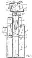
- the fluid mixture to be separated into phases is introduced into the apparatus illustrated in Figure 1 by a tangential conduit 11 leading to a cylindrical separation chamber 13 at the top of a cylindrical container 12.
- a co-axial inner cylinder 14 extending through the full height of the container 12.
- the separation chamber 13 is defined at its lower end by a buffle 21 extending outwards from the inner cylinder to a peripheral wall 22 which baffle defines with the wall of the container 12 an annular gap 23 whose (radial) width is slightly less than the (axial) length of the peripheral. wall. In this particular example the width is just under 75% of the length.
- the baffle 21 is undercut at its lower side 24, but presents a continuous upper plane surface 25 and the wall 22 is a continuous outer cylindrical surface. Possible variations of the baffle are described in the simultaneously filed international application based on GB 9723341.5 and 9819071.5, and features from the statements oif invention in that application may be combined with the separator of the present invention. Furthermore, features from the statements of invention in the simultaneously filed international application based on GB 9723342.3 and 9817074.9 may be combined with the separator of the present invention.
- the container 12 defines with the inner cylinder 14 an annular collection chamber 31 to which the only access in the assembled state of the apparatus is through the gap 23.
- the apparatus can be disassembled by removing the lower portions 32, 32' of the two cylinders which are formed as a single unit joined by a common base 33.
- the cylindrical container 12 splits at a level 34 just below the top of the baffle and the inner cylinder splits at a slightly lower level 35, still within the length of the baffle, and its upper end fits within a recess 36 in the upper part 15 of the inner cylinder 14 within the baffle.
- the split in the cylindrical container is shown as a butt join, but some means of making the join more fluid-tight may be provided.
- a bayonet fitting may be provided to join the cylinders at their split planes; external clamps are another suitable joining means.
- Annular closed cell foam seals (not shown) may be provided to make the joins fluid-tight.
- the central cylinder is surrounded by a frusto conical perforated shroud 41, tapering outwardly towards the top of the container 12 and defining the inner boundary of the separation chamber.
- the volume between the shroud and the inner cylinder provides an outlet duct 42 which continues to taper outwardly above the shroud and then becomes cylindrical at 43.
- the apparatus so far described forms the first stage of the separator.
- Fluid mixture flowing in the tangential conduit 11 is caused to swirl around the separation chamber 13 as it enters that chamber, the lighter phases tending to move to the smaller radii and heavier phases to the greater radii where they will diffuse and fall under gravity through the gap 23 to the collection chamber 31.
- the proportions and dimensions of the gap 23 are chosen so that sufficient heavier phase fluid passes through the gap and very little of the heavier phase fluid in the collection chamber 31 is drawn back through the gap.
- the provision of one or more annular co-axial baffles (not shown) on the base 33 assist the retention of heavier phases against re-entrainment.
- This first stage of the separator is an initial stage, in which efficiency is not of prime importance. In a vacuum cleaner application, it serves to remove the fluff and heavier dirt particles from the flow.
- the shape of the separation chamber and the relationship of its inlet are not critical. The critical separation occurs in the later stages to those described below and it is these stages which embody the essential features of the invention.
- the cylindrical part 43 of the outlet duct 42 of the first stage has a tangential outlet 44 leading by means not shown to the inlet conduit 51 of a second stage which has involute shaped inlet and outlet chambers 52, 53 with an intermediate chamber 54 which joins the inlet and outlet chambers along the common axis 55 of the three chambers.
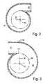
- the curved wall of the inlet chamber decreases from a maximum radius at 56 to a minimum radius at 57 as it subtends the full 360 degrees around the axis 55.
- the downstream end of the inlet conduit 51 is defined on the outside 56 by the curved wall of maximum radius and on the inside 57 by the curved wall of minimum radius.
- the radius decreases gradually, the curved wall having at least three, and in this embodiment four, sections of constant radius and subtending equal angles (90 degrees) at their respective centres, adjacent sections being centred about points on the common normal to the adjacent ends of those portions (thus making those common ends tangential), the radii of successive sections increasing from the minimum to the maximum.
- the innermost section of the involute is centred on the normal 58 which passes through the axis 55.
- the radius of the inlet end 59 of the intermediate chamber 54 is not greater than the minimum radius of the inlet involute and in this embodiment is smaller than the smallest of the four radii.
- the intermediate chamber 54 is frusto-conical, tapering inwardly to a smaller radius at its outlet end 61 which is not greater than and in this embodiment is smaller than the minimum radius of the outlet involute.
- the radius of the intermediate chamber 54 is of course smaller than the minimum radius of the inlet involute.
- the curved wall of the outlet involute gradually increases in radius in subtending the full 360 degrees leading to an outlet conduit 62 for heavier phases in the opposite manner to that described for the inlet involute, the involutes being arranged to receive fluids swirling in the same sense about the stage axis 55 as the swirl induced in the inlet involute.
- the inlet involute chamber 52 has an axial inlet 67 of radius small compared to all the radii of the chambers, in this example being one quarter of the minimum radius of the inlet involute.
- the fluid mixture flowing in the inlet conduit 51 of the second stage follows the increasing curvature of the curved wall of the inlet involute and so swirls around the axis 55 with increasing velocity.
- the heavier phases tend to move to the outer radii and the lighter phases tend to move towards the axis of the stage.
- the velocity of swirl is increased by the small entry radius of the intermediate chamber and further by its taper.
- the lighter phases near the axis will therefore leave the intermediate chamber through the axial outlet cylinder 63, whereas those phases at greater radii will be urged by the tapered shield 65 into the outlet involute around the curved wall of which they will swirl towards the outlet conduit 62.
- the swirling fluids in the inlet involute will create a low pressure point therein on the axis 55, so that fluids presented at the axial inlet 67 will tend to be drawn into this stage of the separator to move along the stage axis, as will be described later.
- the outlet conduit 62 of the second stage is connected by means not shown to an inlet conduit 71 which is tangential to the cylindrical inlet chamber 72 of a third stage, which is itself of a conventional form.
- the inlet chamber opens on one side into a co-axial frusto-conical chamber 73 which tapers from a maximum radius equal to that of the inlet chamber 72 to a minimum at the other end where there is an axial outlet 76 for heavier phases, located within the upper part 15 of the inner cylinder of the first stage at a level within the shroud 41.
- a cylindrical duct 74 coaxial with the inlet chamber 72 has a mouth at the one side of the inlet chamber formed with a radiused inner rim 75 and extends therefrom through that chamber 72 to connect with the axial inlet 67 of the second stage, the axes of the three stages being in this embodiment coincident at 55 and vertical, the outlet 76 of the frusto-conical chamber 73 being at the lowest point of the third stage.
- Fluid mixture flowing in the inlet conduit 71 of the third stage is caused to swirl around the chamber 72 as it is deflected around its curved wall, thus providing further separation of the phases.
- the lighter phases tend to move towards the axis 55 where they reverse axial direction and enter the inner cylinder 74 and are drawn back into the axial inlet 67 of the second stage by the reduced pressure on the axis of the inlet chamber 52 of that second stage, thus being re-subjected to the separation processes of the second and third stages.
- the flow which is recirculated from outlet 62 back through the inlet 74 is about 5 to 30% of the flow which exits through the outlet 63.
- the third stage By recirculating this fraction, it is possible to form the third stage much smaller in volume than if the third stage had to deal with the whole flow through the second stage.
- the location of the inner cylinder 74 within the inlet chamber 72 provides a vortex finder as this third stage of the separator.
- the heavier phases in the chamber 72 tend to move to greater radii within the frusto conical chamber 73 as they continue to swirl, moving down the tapering wall towards the lower end of that chamber to leave by the outlet 76 at the lower end, to continue to the base 33 of the inner cylinder 14 of the first stage.
- Heavier phases from the first and third stages therefore collect at the base 33 of the first stage container, those from the first stage within the annular chamber 31 and those from the third stage within the chamber within cylinder 32'. Both these chambers can be emptied by splitting the container as described above. Since there is only a small overlap between the portions of the container 12 across the split, the removal can be effected easily without knocking the upper portion which knocking might cause heavier phases such as dust to be dislodged, falling when the lower portion is no longer in place to collect them.
- the apparatus is a vacuum cleaner and the mixture of fluid phases comprises dust particles entrained in air.
- Other mixtures which could be separated include silt entrained in a liquid or a mixture of oil and water. Gases, liquids or solids of different density, or any combinations thereof, or gas that is dissolved in liquid can be supplied to the inlet chamber.
Landscapes
- Engineering & Computer Science (AREA)
- Mechanical Engineering (AREA)
- Cyclones (AREA)
Claims (14)
- Zyklonseparator, aufweisend:dadurch gekennzeichnet, dass:eine evolventenförmige Einlasskammer (52);eine evolventenförmige Auslasskammer (53);einen Fluideinlass (51), der durch die gekrümmte Wandung der Einlasskammerevolventen mit maximalem Radius festgelegt ist, um ein Fluidgemisch in die Einlasskammer (52) derart einzuleiten, dass es um die Einlasskammer (52) verwirbelt und zur Auslasskammer (5) hindurchtritt, in welcher es um eine Auslasskammerachse (55) verwirbelt, wobei die Auslasskammer (53) mit einem Leichtphasenauslass (63) zum Leiten von Fluiden leichterer Phase versehen ist;die Auslasskammer (53) außerdem mit einem Schwerphasenauslass (62) versehen ist, der durch die gekrümmte Wandung der Auslasskammerevolventen mit maximalem Radius festgelegt ist, um Fluide schwererer Phase aus der Auslasskammer zu leiten, wobei der Schwerphasenauslass (62) unter einem relativ großen Abstand von der Auslasskammerachse vorgesehen ist, und wobei der Leichtphasenauslass (63) unter einem relativ kleinen Abstand von der Auslasskammerachse (55) vorgesehen ist;und dass:die Einlasskammer (52) und die Auslasskammer (53) voneinander beabstandet sind und eine Zwischenkammer (54) dazwischen vorgesehen ist, durch welche das Fluid im Einsatz vorwirbelt, wenn es von der Einlasskammer (52) zur Auslasskammer (53) hindurchtritt.
- Separator nach Anspruch 1, wobei die Evolventen eine gemeinsam Achse (55) aufweisen und so angeordnet sind, dass durch sie stromende Fluide weiterhin in derselben Richtung um die Achse verwirbeln.
- Separator nach Anspruch 1 oder 2, wobei eine der Evolventen eine gekrümmte Wandung aufweist, die aus zumindest drei bogenförmigen Abschnitten gleichmäßiger Krümmung gebildet sind, wobei jeder Abschnitt eine kleinere Krümmung aufweist, als der vorangehende Innenabschnitt, wobei die benachbarten Abschnitte mit ihren Zentren auf einer gemeinsamen Normalen zu den benachbarten Enden dieser Abschnitte liegen.
- Separator nach Anspruch 3, aufweisend vier der Abschnitte.
- Separator nach einem der vorangehenden Ansprüche, aufweisend Einrichtungen (71, 72, 74, 75) zum Leiten von einem Teil des Fluids von dem Schwerphasenauslass (62) der Auslasskammer (53) zu einem zusätzlichen Einlass (67) der auf der Verwirbelungsachse (55) des Fluids angeordnet ist, das durch den Fluideinlass (51) der Einlasskammer (52) eingeleitet wird.
- Separator nach Anspruch 5, wobei die leitende Einrichtung außerdem eine Trennstufe (72, 74, 75) für Fluide aus dem Schwerphasenauslass (62) der Auslasskammer (63) aufweist, wobei der Auslass (74) von der weiteren Stufe für leichtere Phasen im Gebrauch zu dem zusätzlichen Einlass (67) geleitet ist.
- Separator nach Anspruch 6, wobei die leitende Einrichtung (71) so angeordnet ist, dass sie das gesamte Fluid aus dem Schwerphasenauslass (62) der Auslasskammer (53) zu der weiteren Stufe (72, 74, 75) leitet.
- Separator nach Anspruch 5, 6 oder 7, wobei der Fluideinlass (51) und der zusätzliche Einlass (67) der Einlasskammer (52) am gegenüberliegenden Ende eines Körpers angeordnet sind, der die Auslasskammer (52), die Zwischenkammer (54) und die Auslasskammer (53) umfasst, zu den Auslässen der Auslasskammer (53) für die schwere (62) und die leichte (63) Phase.
- Separator nach Anspruch 5, 6, 7 oder 8, wobei der zusätzliche Einlass (67) einen Radius aufweist, der nicht größer ist als 50% des minimalen Radius der Einlassevolventen (52).
- Separator nach Anspruch 9, wobei der zusätzliche Einlass (67) einen Radius aufweist, der kleiner ist als der (bzw. derjenige) des Leichtphaseneinlasses (63) der Auslasskammer (53).
- Separator nach einem der vorangehenden Ansprüche, wobei die Zwischenkammer (54) sich ausgehend von der Einlasskammer (52) zur Auslasskammer (53) einwärts verjüngt.
- Separator nach einem der vorangehenden Ansprüche, wobei der Leichtphasenauslass (63) der Auslasskammer (53) einen Kanal umfasst, der in die Evolvente der Auslasskammer (53) derart sich erstreckt, dass ein Wirbelfinder gebildet ist.
- Staubsauger, aufweisend einen Zyklonseparator nach einem der vorangehenden Ansprüche.
- Verfahren zum Trennen von Gasen, Flussigkeiten oder Feststoffen unterschiedlicher Dichte oder von Kombinationen aus diesen, aufweisend den Schritt: Einleiten derselben als verwirbeltes Gemisch in den Zyklonseparator nach einem der Ansprüche 1 bis 12.
Applications Claiming Priority (5)
| Application Number | Priority Date | Filing Date | Title |
|---|---|---|---|
| GB9723345 | 1997-11-04 | ||
| GBGB9723345.6A GB9723345D0 (en) | 1997-06-03 | 1997-11-04 | Fluid rotation |
| GB9817073 | 1998-08-05 | ||
| GBGB9817073.1A GB9817073D0 (en) | 1997-11-04 | 1998-08-05 | Phase separator |
| PCT/GB1998/003306 WO1999022873A1 (en) | 1997-11-04 | 1998-11-04 | Cyclone separator |
Publications (2)
| Publication Number | Publication Date |
|---|---|
| EP1028811A1 EP1028811A1 (de) | 2000-08-23 |
| EP1028811B1 true EP1028811B1 (de) | 2002-04-17 |
Family
ID=26312551
Family Applications (1)
| Application Number | Title | Priority Date | Filing Date |
|---|---|---|---|
| EP98951605A Expired - Lifetime EP1028811B1 (de) | 1997-11-04 | 1998-11-04 | Zyklonabscheider |
Country Status (7)
| Country | Link |
|---|---|
| US (1) | US6398973B1 (de) |
| EP (1) | EP1028811B1 (de) |
| AU (1) | AU9755898A (de) |
| CA (1) | CA2308410A1 (de) |
| DE (1) | DE69804995T2 (de) |
| GB (1) | GB9817073D0 (de) |
| WO (1) | WO1999022873A1 (de) |
Cited By (5)
| Publication number | Priority date | Publication date | Assignee | Title |
|---|---|---|---|---|
| US7556715B2 (en) | 2004-01-09 | 2009-07-07 | Suncor Energy, Inc. | Bituminous froth inline steam injection processing |
| US7726491B2 (en) | 2002-09-19 | 2010-06-01 | Suncor Energy Inc. | Bituminous froth hydrocarbon cyclone |
| US7736501B2 (en) | 2002-09-19 | 2010-06-15 | Suncor Energy Inc. | System and process for concentrating hydrocarbons in a bitumen feed |
| US8968580B2 (en) | 2009-12-23 | 2015-03-03 | Suncor Energy Inc. | Apparatus and method for regulating flow through a pumpbox |
| US10167706B2 (en) | 2015-03-13 | 2019-01-01 | Caltec Production Solutions Limited | Oil/gas production apparatus |
Families Citing this family (67)
| Publication number | Priority date | Publication date | Assignee | Title |
|---|---|---|---|---|
| US6344064B1 (en) * | 1999-01-29 | 2002-02-05 | Fantom Technologies Inc. | Method and apparatus of particle transfer in multi-stage particle separators |
| US7121997B2 (en) | 1999-06-09 | 2006-10-17 | Ethicon, Inc. | Surgical instrument and method for treating female urinary incontinence |
| US6558453B2 (en) * | 2000-01-14 | 2003-05-06 | White Consolidated Industries, Inc. | Bagless dustcup |
| US6910245B2 (en) | 2000-01-14 | 2005-06-28 | White Consolidated Industries, Inc. | Upright vacuum cleaner with cyclonic air path |
| AU2001267732A1 (en) * | 2000-07-06 | 2002-01-21 | John Herbert North | Improved air/particle separator |
| EP1520505B1 (de) * | 2000-07-06 | 2006-02-15 | John Herbert North | Verbesserte Staub-/Teilchensammelvorrichtung für Zyklonabscheider |
| KR20020091510A (ko) * | 2001-05-31 | 2002-12-06 | 삼성광주전자 주식회사 | 진공청소기용 사이클론 집진장치 |
| KR100412586B1 (ko) * | 2001-06-01 | 2003-12-31 | 삼성광주전자 주식회사 | 진공청소기용 사이클론 집진장치의 그릴 조립체 |
| KR100478641B1 (ko) * | 2002-06-04 | 2005-03-24 | 삼성광주전자 주식회사 | 진공청소기용 사이클론 집진장치 |
| GB2399864A (en) | 2003-03-22 | 2004-09-29 | Ellastar Ltd | A system and process for pumping multiphase fluids |
| US7544224B2 (en) | 2003-08-05 | 2009-06-09 | Electrolux Home Care Products, Inc. | Cyclonic vacuum cleaner |
| US7341611B2 (en) * | 2004-03-17 | 2008-03-11 | Euro-Pro Operating, Llc | Compact cyclonic bagless vacuum cleaner |
| GB0410961D0 (en) * | 2004-05-17 | 2004-06-16 | Caltec Ltd | A separation system for handling and boosting the production of heavy oil |
| US8075668B2 (en) | 2005-03-29 | 2011-12-13 | Dresser-Rand Company | Drainage system for compressor separators |
| WO2007016698A2 (en) | 2005-08-04 | 2007-02-08 | C.R. Bard, Inc. | Pelvic implant systems and methods |
| CA2526336C (en) | 2005-11-09 | 2013-09-17 | Suncor Energy Inc. | Method and apparatus for oil sands ore mining |
| US8168071B2 (en) | 2005-11-09 | 2012-05-01 | Suncor Energy Inc. | Process and apparatus for treating a heavy hydrocarbon feedstock |
| CA2827237C (en) | 2005-11-09 | 2016-02-09 | Suncor Energy Inc. | Mobile oil sands mining system |
| FR2892953B1 (fr) | 2005-11-09 | 2008-06-27 | Saipem S A Sa | Procede et dispositif de separation de liquide polyphasique |
| EP1948073B1 (de) | 2005-11-14 | 2014-03-19 | C.R.Bard, Inc. | Bandankersystem |
| CN100420416C (zh) * | 2006-04-06 | 2008-09-24 | 苏州金莱克家用电器有限公司 | 多进风口分离装置及含有该装置的尘杯装置 |
| GB2440726B (en) * | 2006-08-12 | 2011-05-18 | Caltec Ltd | Cyclonic separator and a method of separating fluids |
| US8480559B2 (en) | 2006-09-13 | 2013-07-09 | C. R. Bard, Inc. | Urethral support system |
| EP2063978B1 (de) | 2006-09-19 | 2014-07-09 | Dresser-Rand Company | Dichtung für drehabscheidertrommel |
| CA2663531C (en) | 2006-09-21 | 2014-05-20 | William C. Maier | Separator drum and compressor impeller assembly |
| MX2009003175A (es) | 2006-09-25 | 2009-04-03 | Dresser Rand Co | Cubierta de acceso para bobina conectora presurizada. |
| WO2008039733A2 (en) | 2006-09-25 | 2008-04-03 | Dresser-Rand Company | Compressor mounting system |
| CA2663883C (en) | 2006-09-25 | 2015-02-03 | Kevin M. Majot | Coupling guard system |
| WO2008039446A2 (en) | 2006-09-25 | 2008-04-03 | Dresser-Rand Company | Fluid deflector for fluid separator devices |
| BRPI0717087B1 (pt) | 2006-09-25 | 2018-10-16 | Dresser Rand Co | sistema de carretel conector para conectar um primeiro componente e um segundo componente de um sistema de compressão industrial |
| EP2415507A1 (de) | 2006-09-26 | 2012-02-08 | Dresser-Rand Company | Verbesserte statische Flüssigkeitstrennungsvorrichtung |
| US7713335B2 (en) * | 2006-10-30 | 2010-05-11 | Caterpillar Inc. | Air separator |
| US8206280B2 (en) | 2007-11-13 | 2012-06-26 | C. R. Bard, Inc. | Adjustable tissue support member |
| WO2009111616A2 (en) | 2008-03-05 | 2009-09-11 | Dresser-Rand Company | Compressor assembly including separator and ejector pump |
| US8062400B2 (en) | 2008-06-25 | 2011-11-22 | Dresser-Rand Company | Dual body drum for rotary separators |
| US8079805B2 (en) | 2008-06-25 | 2011-12-20 | Dresser-Rand Company | Rotary separator and shaft coupler for compressors |
| US7922218B2 (en) | 2008-06-25 | 2011-04-12 | Dresser-Rand Company | Shear ring casing coupler device |
| GB2461874B (en) | 2008-07-14 | 2012-11-21 | Caltec Ltd | Separation system and method |
| US8210804B2 (en) | 2009-03-20 | 2012-07-03 | Dresser-Rand Company | Slidable cover for casing access port |
| US8087901B2 (en) | 2009-03-20 | 2012-01-03 | Dresser-Rand Company | Fluid channeling device for back-to-back compressors |
| US8061972B2 (en) | 2009-03-24 | 2011-11-22 | Dresser-Rand Company | High pressure casing access cover |
| US8414692B2 (en) | 2009-09-15 | 2013-04-09 | Dresser-Rand Company | Density-based compact separator |
| JP4621802B1 (ja) * | 2010-02-09 | 2011-01-26 | 株式会社ワールドケミカル | 自吸式固液分離装置 |
| US9095856B2 (en) | 2010-02-10 | 2015-08-04 | Dresser-Rand Company | Separator fluid collector and method |
| WO2012009158A2 (en) | 2010-07-15 | 2012-01-19 | Dresser-Rand Company | Enhanced in-line rotary separator |
| US8663483B2 (en) | 2010-07-15 | 2014-03-04 | Dresser-Rand Company | Radial vane pack for rotary separators |
| US8657935B2 (en) | 2010-07-20 | 2014-02-25 | Dresser-Rand Company | Combination of expansion and cooling to enhance separation |
| US8821362B2 (en) | 2010-07-21 | 2014-09-02 | Dresser-Rand Company | Multiple modular in-line rotary separator bundle |
| JP5936144B2 (ja) | 2010-09-09 | 2016-06-15 | ドレッサー ランド カンパニーDresser−Rand Company | 洗浄可能に制御された排水管 |
| US8994237B2 (en) | 2010-12-30 | 2015-03-31 | Dresser-Rand Company | Method for on-line detection of liquid and potential for the occurrence of resistance to ground faults in active magnetic bearing systems |
| EP2659277B8 (de) | 2010-12-30 | 2018-05-23 | Dresser-Rand Company | Verfahren zur online-erkennung von bodenwiderstandsfehlern in aktiven magnetlagersystemen |
| US9551349B2 (en) | 2011-04-08 | 2017-01-24 | Dresser-Rand Company | Circulating dielectric oil cooling system for canned bearings and canned electronics |
| US8876389B2 (en) | 2011-05-27 | 2014-11-04 | Dresser-Rand Company | Segmented coast-down bearing for magnetic bearing systems |
| US8851756B2 (en) | 2011-06-29 | 2014-10-07 | Dresser-Rand Company | Whirl inhibiting coast-down bearing for magnetic bearing systems |
| US8955691B2 (en) | 2011-08-30 | 2015-02-17 | Jason E. Bramlett | Spiral ramp hydrocyclone |
| GB2499620B (en) | 2012-02-21 | 2019-05-22 | Caltec Production Solutions Ltd | Fluid separator |
| US8973215B2 (en) | 2012-07-18 | 2015-03-10 | Techtronic Floor Care Technology Limited | Cyclonic vacuum cleaner and dirt separator |
| WO2014072469A1 (en) | 2012-11-09 | 2014-05-15 | Aktiebolaget Electrolux | Cyclone dust separator arrangement, cyclone dust separator and cyclone vacuum cleaner |
| US9366206B2 (en) * | 2012-12-17 | 2016-06-14 | Ford Global Technologies, Llc | Fuel-air separator and pulse dampener |
| GB2524820A (en) * | 2014-04-04 | 2015-10-07 | Caltec Ltd | Jet pump |
| EP3250327B1 (de) | 2015-01-26 | 2022-09-28 | Hayward Industries, Inc. | Schwimmbadreiniger mit hydrozyklonischem partikelabscheider und/oder sechswalzenantriebssystem |
| US9885196B2 (en) | 2015-01-26 | 2018-02-06 | Hayward Industries, Inc. | Pool cleaner power coupling |
| US9795898B2 (en) | 2015-03-31 | 2017-10-24 | Jci Cyclonics Ltd. | Cyclonic separator system |
| CN105080737A (zh) * | 2015-10-09 | 2015-11-25 | 北京柯林柯矿业科技有限公司 | 三产品重介质旋流器 |
| US9885194B1 (en) | 2017-05-11 | 2018-02-06 | Hayward Industries, Inc. | Pool cleaner impeller subassembly |
| US9896858B1 (en) | 2017-05-11 | 2018-02-20 | Hayward Industries, Inc. | Hydrocyclonic pool cleaner |
| US10156083B2 (en) | 2017-05-11 | 2018-12-18 | Hayward Industries, Inc. | Pool cleaner power coupling |
Family Cites Families (43)
| Publication number | Priority date | Publication date | Assignee | Title |
|---|---|---|---|---|
| US22334A (en) | 1858-12-14 | stern | ||
| DE113599C (de) | 1952-10-15 | |||
| US2837172A (en) | 1955-09-15 | 1958-06-03 | Ca Nat Research Council | Centrifugal separator |
| US3481118A (en) | 1968-04-22 | 1969-12-02 | Porta Test Mfg | Cyclone separator |
| NL167614C (nl) | 1972-03-04 | 1982-01-18 | Nederlandse Gasunie Nv | Inrichting voor het afscheiden van vaste stoffen en vloeistoffen uit een gasstroom. |
| JPS5579061A (en) * | 1978-12-07 | 1980-06-14 | Kawasaki Heavy Ind Ltd | Dust collector |
| US4251241A (en) | 1979-07-05 | 1981-02-17 | Windsor Industries, Inc. | Cyclone-type aspirated separator for washing dirt-laden dry airstreams |
| DE2946572A1 (de) | 1979-11-19 | 1981-05-27 | Rolf Dr.-Ing. 4200 Oberhausen Noack | Staubsaugersystem |
| US4246013A (en) | 1979-11-21 | 1981-01-20 | Andrew Truhan | Cyclone type air/particulate concentrator and collector |
| SE426958B (sv) | 1980-02-25 | 1983-02-21 | Celleco Ab | Separator for uppdelning av en inkommande blandning av cellulosasuspension eller liknande och grova tunga partiklar |
| US5160356A (en) | 1980-06-19 | 1992-11-03 | Notetry Limited | Vacuum cleaning apparatus |
| DE3171910D1 (en) | 1980-06-19 | 1985-09-26 | Rotork Appliances Ltd | Vacuum cleaning appliance |
| US4305825A (en) | 1980-08-20 | 1981-12-15 | Laval Claude C | Reaction member for a fluid separating device |
| SE434469B (sv) | 1982-12-13 | 1984-07-30 | Soederhamn Ind Arbetshygien Ab | Stoftavskiljaraggregat |
| US4455220A (en) | 1982-12-23 | 1984-06-19 | Shell Oil Company | Separation of fluid cracking catalyst particles from gaseous hydrocarbons |
| JPS59189952A (ja) | 1983-04-14 | 1984-10-27 | Ube Ind Ltd | サイクロン |
| US4643748A (en) | 1986-02-24 | 1987-02-17 | Notetry Limited | Cleaning apparatus |
| DE3936078C2 (de) | 1989-10-30 | 1994-02-10 | Guenter Dr Ing Slowik | Drallerzeuger für Zyklonabscheider |
| US5180486A (en) | 1989-11-28 | 1993-01-19 | Lsr Environmental Systems Company | Potential flow centrifugal separator system for removing solid particulates from a fluid stream |
| US5080697A (en) | 1990-04-03 | 1992-01-14 | Nutone, Inc. | Draw-down cyclonic vacuum cleaner |
| FR2662619B1 (fr) * | 1990-06-05 | 1993-02-05 | Inst Francais Du Petrole | Melangeur-separateur cyclonique a co-courant et ses applications. |
| US5078761A (en) | 1990-07-06 | 1992-01-07 | Notetry Limited | Shroud |
| US5062870A (en) | 1990-07-06 | 1991-11-05 | Notetry Limited | Shut-off device for cyclonic vacuum cleaner |
| US5090976A (en) | 1990-09-21 | 1992-02-25 | Notetry Limited | Dual cyclonic vacuum cleaner with disposable liner |
| SU1764625A1 (ru) | 1990-09-27 | 1992-09-30 | В.А.Д тлов и Б.В.Иванов | Пылесос дл уборки пыли и порошка |
| SE465949B (sv) | 1990-10-01 | 1991-11-25 | Akp Tekno Oy | Centralenhet foer centraldammsugare |
| NL9002668A (nl) | 1990-12-05 | 1992-07-01 | Philips Nv | Stofzuiger. |
| RU2034513C1 (ru) | 1991-05-14 | 1995-05-10 | Сергей Владимирович Геллер | Пылесос и способ его эксплуатации |
| US5137554A (en) | 1991-09-09 | 1992-08-11 | Fasco Industries, Inc. | Cyclonic vacuum cleaner cone |
| GB9123883D0 (en) | 1991-11-11 | 1992-01-02 | Bhr Group Ltd | Hydrocyclone |
| GB2271728B (en) | 1992-10-15 | 1997-04-02 | Edward John Roberts | Suction cleaners |
| US5558697A (en) | 1992-12-08 | 1996-09-24 | Notetry Limited | Dual cyclonic vacuum cleaner |
| AU677306B2 (en) | 1993-05-26 | 1997-04-17 | Zumro B.V. | Inflatable body |
| DK119093A (da) | 1993-10-22 | 1995-04-23 | Joergen Sjoegreen | Universalstøvsuger |
| SE504247C2 (sv) * | 1994-03-24 | 1996-12-16 | Gaevle Galvan Tryckkaerl Ab | Kärl för behandling av vätska |
| GB2295311A (en) | 1994-11-24 | 1996-05-29 | Notetry Ltd | Filter assembly for vacuum cleaner |
| GB9425812D0 (en) | 1994-12-21 | 1995-02-22 | Notetry Ltd | Improved dust separation apparatus |
| MY112609A (en) | 1994-12-21 | 2001-07-31 | Dyson Technology Ltd | Improved dust separation apparatus |
| GB2296452A (en) | 1994-12-28 | 1996-07-03 | Notetry Ltd | Shroud for cyclone separator |
| GB2296879A (en) | 1995-01-10 | 1996-07-17 | Notetry Ltd | Dust separation apparatus |
| GB2297243A (en) | 1995-01-27 | 1996-07-31 | Notetry Ltd | Vacuum cleaner for use on stairs |
| NO953468D0 (no) | 1995-09-04 | 1995-09-04 | Read Process Engineering As | Hydrosyklon-Separasjon-Disk (HS-Disk) |
| GB9625999D0 (en) * | 1996-12-13 | 1997-01-29 | Hesse Wayne W | Hydrocyclone |
-
1998
- 1998-08-05 GB GBGB9817073.1A patent/GB9817073D0/en not_active Ceased
- 1998-11-04 DE DE69804995T patent/DE69804995T2/de not_active Expired - Lifetime
- 1998-11-04 WO PCT/GB1998/003306 patent/WO1999022873A1/en not_active Ceased
- 1998-11-04 EP EP98951605A patent/EP1028811B1/de not_active Expired - Lifetime
- 1998-11-04 CA CA002308410A patent/CA2308410A1/en not_active Abandoned
- 1998-11-04 AU AU97558/98A patent/AU9755898A/en not_active Abandoned
- 1998-11-04 US US09/530,846 patent/US6398973B1/en not_active Expired - Lifetime
Cited By (7)
| Publication number | Priority date | Publication date | Assignee | Title |
|---|---|---|---|---|
| US7726491B2 (en) | 2002-09-19 | 2010-06-01 | Suncor Energy Inc. | Bituminous froth hydrocarbon cyclone |
| US7736501B2 (en) | 2002-09-19 | 2010-06-15 | Suncor Energy Inc. | System and process for concentrating hydrocarbons in a bitumen feed |
| US7556715B2 (en) | 2004-01-09 | 2009-07-07 | Suncor Energy, Inc. | Bituminous froth inline steam injection processing |
| US7914670B2 (en) | 2004-01-09 | 2011-03-29 | Suncor Energy Inc. | Bituminous froth inline steam injection processing |
| US8685210B2 (en) | 2004-01-09 | 2014-04-01 | Suncor Energy Inc. | Bituminous froth inline steam injection processing |
| US8968580B2 (en) | 2009-12-23 | 2015-03-03 | Suncor Energy Inc. | Apparatus and method for regulating flow through a pumpbox |
| US10167706B2 (en) | 2015-03-13 | 2019-01-01 | Caltec Production Solutions Limited | Oil/gas production apparatus |
Also Published As
| Publication number | Publication date |
|---|---|
| GB9817073D0 (en) | 1998-10-07 |
| US6398973B1 (en) | 2002-06-04 |
| EP1028811A1 (de) | 2000-08-23 |
| AU9755898A (en) | 1999-05-24 |
| WO1999022873A1 (en) | 1999-05-14 |
| CA2308410A1 (en) | 1999-05-14 |
| DE69804995D1 (de) | 2002-05-23 |
| DE69804995T2 (de) | 2002-11-28 |
Similar Documents
| Publication | Publication Date | Title |
|---|---|---|
| EP1028811B1 (de) | Zyklonabscheider | |
| EP1059993B1 (de) | Reinigungsvorrichtung | |
| US6531066B1 (en) | Cyclone separator | |
| US6896720B1 (en) | Cleaning apparatus | |
| US6596046B2 (en) | Cyclone separator having a variable longitudinal profile | |
| US6190543B1 (en) | Cyclonic separator | |
| EP1162910B1 (de) | Staubsauger mit zyklon.staubsammelvorrichtung | |
| US4212653A (en) | Process and apparatus for separating particulate matter from gaseous media | |
| US4378289A (en) | Method and apparatus for centrifugal separation | |
| EP1842475A1 (de) | Zweite Sortiervorrichtung für einen Staubsauger | |
| EP1028812B1 (de) | Zyklonabscheider | |
| US20070175189A1 (en) | Cyclonic separating apparatus | |
| KR20010080209A (ko) | 사이클로닉 분리 장치 | |
| US20030006188A1 (en) | Separator for liquids containing impurities | |
| JPS6318447Y2 (de) | ||
| US20230302468A1 (en) | A compact disc stack cyclone separator | |
| GB2330786A (en) | Cyclone separator | |
| GB2367019A (en) | Cyclone separator | |
| US4278452A (en) | Cyclone separator | |
| HU209077B (en) | Method and apparatus for separating materials from media | |
| GB2136325A (en) | Improvements In or Relating To Cyclone Separators | |
| US5236587A (en) | Process and apparatus for the separation of materials from a medium | |
| CA2025842C (en) | Process and apparatus for the separation of materials from a medium | |
| CN1175483A (zh) | 旋风式集尘装置 | |
| SU768474A1 (ru) | Вихревой пылеуловитель |
Legal Events
| Date | Code | Title | Description |
|---|---|---|---|
| PUAI | Public reference made under article 153(3) epc to a published international application that has entered the european phase |
Free format text: ORIGINAL CODE: 0009012 |
|
| 17P | Request for examination filed |
Effective date: 20000503 |
|
| AK | Designated contracting states |
Kind code of ref document: A1 Designated state(s): DE FR GB IE IT NL |
|
| GRAG | Despatch of communication of intention to grant |
Free format text: ORIGINAL CODE: EPIDOS AGRA |
|
| RBV | Designated contracting states (corrected) |
Designated state(s): DE FR GB IE IT NL |
|
| 17Q | First examination report despatched |
Effective date: 20010404 |
|
| GRAG | Despatch of communication of intention to grant |
Free format text: ORIGINAL CODE: EPIDOS AGRA |
|
| GRAH | Despatch of communication of intention to grant a patent |
Free format text: ORIGINAL CODE: EPIDOS IGRA |
|
| REG | Reference to a national code |
Ref country code: GB Ref legal event code: IF02 |
|
| GRAH | Despatch of communication of intention to grant a patent |
Free format text: ORIGINAL CODE: EPIDOS IGRA |
|
| GRAA | (expected) grant |
Free format text: ORIGINAL CODE: 0009210 |
|
| AK | Designated contracting states |
Kind code of ref document: B1 Designated state(s): DE FR GB IE IT NL |
|
| PG25 | Lapsed in a contracting state [announced via postgrant information from national office to epo] |
Ref country code: NL Free format text: LAPSE BECAUSE OF FAILURE TO SUBMIT A TRANSLATION OF THE DESCRIPTION OR TO PAY THE FEE WITHIN THE PRESCRIBED TIME-LIMIT Effective date: 20020417 |
|
| REG | Reference to a national code |
Ref country code: IE Ref legal event code: FG4D |
|
| REF | Corresponds to: |
Ref document number: 69804995 Country of ref document: DE Date of ref document: 20020523 |
|
| NLV1 | Nl: lapsed or annulled due to failure to fulfill the requirements of art. 29p and 29m of the patents act | ||
| ET | Fr: translation filed | ||
| PG25 | Lapsed in a contracting state [announced via postgrant information from national office to epo] |
Ref country code: IE Free format text: LAPSE BECAUSE OF NON-PAYMENT OF DUE FEES Effective date: 20021104 |
|
| PLBE | No opposition filed within time limit |
Free format text: ORIGINAL CODE: 0009261 |
|
| STAA | Information on the status of an ep patent application or granted ep patent |
Free format text: STATUS: NO OPPOSITION FILED WITHIN TIME LIMIT |
|
| 26N | No opposition filed |
Effective date: 20030120 |
|
| REG | Reference to a national code |
Ref country code: IE Ref legal event code: MM4A |
|
| REG | Reference to a national code |
Ref country code: GB Ref legal event code: 732E |
|
| REG | Reference to a national code |
Ref country code: FR Ref legal event code: TP |
|
| PGFP | Annual fee paid to national office [announced via postgrant information from national office to epo] |
Ref country code: DE Payment date: 20121121 Year of fee payment: 15 Ref country code: FR Payment date: 20121130 Year of fee payment: 15 |
|
| PGFP | Annual fee paid to national office [announced via postgrant information from national office to epo] |
Ref country code: IT Payment date: 20121127 Year of fee payment: 15 |
|
| REG | Reference to a national code |
Ref country code: FR Ref legal event code: ST Effective date: 20140731 |
|
| REG | Reference to a national code |
Ref country code: DE Ref legal event code: R119 Ref document number: 69804995 Country of ref document: DE Effective date: 20140603 |
|
| PG25 | Lapsed in a contracting state [announced via postgrant information from national office to epo] |
Ref country code: DE Free format text: LAPSE BECAUSE OF NON-PAYMENT OF DUE FEES Effective date: 20140603 Ref country code: IT Free format text: LAPSE BECAUSE OF NON-PAYMENT OF DUE FEES Effective date: 20131104 |
|
| PG25 | Lapsed in a contracting state [announced via postgrant information from national office to epo] |
Ref country code: FR Free format text: LAPSE BECAUSE OF NON-PAYMENT OF DUE FEES Effective date: 20131202 |
|
| PGFP | Annual fee paid to national office [announced via postgrant information from national office to epo] |
Ref country code: GB Payment date: 20170914 Year of fee payment: 20 |
|
| REG | Reference to a national code |
Ref country code: GB Ref legal event code: PE20 Expiry date: 20181103 |
|
| PG25 | Lapsed in a contracting state [announced via postgrant information from national office to epo] |
Ref country code: GB Free format text: LAPSE BECAUSE OF EXPIRATION OF PROTECTION Effective date: 20181103 |