EP1028513A2 - Salient poles support - Google Patents
Salient poles support Download PDFInfo
- Publication number
- EP1028513A2 EP1028513A2 EP00102552A EP00102552A EP1028513A2 EP 1028513 A2 EP1028513 A2 EP 1028513A2 EP 00102552 A EP00102552 A EP 00102552A EP 00102552 A EP00102552 A EP 00102552A EP 1028513 A2 EP1028513 A2 EP 1028513A2
- Authority
- EP
- European Patent Office
- Prior art keywords
- pole
- insulating body
- machine according
- windings
- stator
- Prior art date
- Legal status (The legal status is an assumption and is not a legal conclusion. Google has not performed a legal analysis and makes no representation as to the accuracy of the status listed.)
- Granted
Links
Images

Classifications
-
- H—ELECTRICITY
- H02—GENERATION; CONVERSION OR DISTRIBUTION OF ELECTRIC POWER
- H02K—DYNAMO-ELECTRIC MACHINES
- H02K5/00—Casings; Enclosures; Supports
- H02K5/04—Casings or enclosures characterised by the shape, form or construction thereof
- H02K5/16—Means for supporting bearings, e.g. insulating supports or means for fitting bearings in the bearing-shields
- H02K5/161—Means for supporting bearings, e.g. insulating supports or means for fitting bearings in the bearing-shields radially supporting the rotary shaft at both ends of the rotor
-
- H—ELECTRICITY
- H02—GENERATION; CONVERSION OR DISTRIBUTION OF ELECTRIC POWER
- H02K—DYNAMO-ELECTRIC MACHINES
- H02K1/00—Details of the magnetic circuit
- H02K1/06—Details of the magnetic circuit characterised by the shape, form or construction
- H02K1/12—Stationary parts of the magnetic circuit
- H02K1/14—Stator cores with salient poles
- H02K1/146—Stator cores with salient poles consisting of a generally annular yoke with salient poles
- H02K1/148—Sectional cores
-
- H—ELECTRICITY
- H02—GENERATION; CONVERSION OR DISTRIBUTION OF ELECTRIC POWER
- H02K—DYNAMO-ELECTRIC MACHINES
- H02K3/00—Details of windings
- H02K3/46—Fastening of windings on the stator or rotor structure
- H02K3/52—Fastening salient pole windings or connections thereto
- H02K3/521—Fastening salient pole windings or connections thereto applicable to stators only
- H02K3/524—Fastening salient pole windings or connections thereto applicable to stators only for U-shaped, E-shaped or similarly shaped cores
-
- H—ELECTRICITY
- H02—GENERATION; CONVERSION OR DISTRIBUTION OF ELECTRIC POWER
- H02K—DYNAMO-ELECTRIC MACHINES
- H02K5/00—Casings; Enclosures; Supports
- H02K5/04—Casings or enclosures characterised by the shape, form or construction thereof
- H02K5/12—Casings or enclosures characterised by the shape, form or construction thereof specially adapted for operating in liquid or gas
- H02K5/128—Casings or enclosures characterised by the shape, form or construction thereof specially adapted for operating in liquid or gas using air-gap sleeves or air-gap discs
Definitions
- the invention relates to an electric motor, in particular for Operation of a pump, with a stator by windings has surrounding pole pieces, and with a pole ring, the Surrounds pole piece and to which the pole piece can be detached are attached.
- the invention also relates to Method for producing the stator package of such a Electric motor.
- Electric motors which have a pole ring have molded pole legs, the pole ring in a number of segments corresponding to the number of pole legs can be divided. Since the pole ring and pole leg are one must form such from pole ring and pole legs existing stator packages with so-called needle winders be wound. Doing so will needles from one face of the stator package between the pole legs and thereby the wire is placed around a polar arm.
- This way of wrapping has the disadvantage that the turns of the wire within the Winding have a large number of crossing points what to a correspondingly reduced packing density and thus to increase the winding length (average coil length) leads. At the same time, the correspondingly greater length of the Winding wire the manufacturing cost of the motor what just is particularly important for small engines.
- the object of the present invention is therefore a electrical machine, in particular an electric motor create, the stator package with small size and high efficiency simple and inexpensive by machine can be made.
- it is an object of the invention Method for producing a stator package of the To create motor according to the invention.
- the essence of the invention is that all pole legs of one common insulating body designed as a pole piece support are kept in the after mounting the pole piece in Stator package and thus in the electrical machine especially the electric motor remains.
- This insulating body offers great advantages in the manufacture of motors, than now the individual pole pieces of Coil winders, especially those specially designed for a layer Winding suitable flyer winders, can be wound, before the package of pole pieces held by the insulator is inserted as a whole into the pole ring.
- the wrapping by flyer winder is in contrast to the known Needle winders are particularly advantageous because the windings can be applied in layers and without crossings, so that a compact winding with low application results. Moreover it is possible to wrap with large wire cross sections, so that the windings can be designed for high currents.
- the insulating body according to the invention is advantageously as a completely surrounding and in particular from the rotor Plastic molded sleeve formed in its wall Recesses for inserting or inserting the individual Has pole piece.
- the pole pieces are in kept in the correct position, being wound Base, the winding sections, the pole leg radially from protrude from the outer surface of the jacket.
- Storage in the sleeve-shaped insulating body ensures one hand good access for the winding machine to the winding sections and on the other hand aligns the pole legs in the right one Location for later installation.
- Introducing the Pole leg in the insulating body is particularly simple, if this consists of two axially joinable half shells is constructed. Then the pole legs can be inserted in one Half shell are used before the other half shell final mounting of the pole piece is placed.
- Insulating bodies are on the outside facing away from the rotor frame-shaped brackets surrounding the pole legs intended. These brackets are designed to be the Border the winding sections of the pole legs and templates form on which the stator windings can be wound.
- the insulating body with the holders is advantageously molded in one piece from plastic. On the one hand, this is the ensures cost-effective production of the insulating body, while on the other hand those with rounded corners and edges provided plastic components the winding wires one provide good protection against abrasion of the insulation.
- the insulating body additional functions.
- Front receiving parts are provided in the insulation displacement contacts for contacting the stator windings can be used.
- the receiving parts can be injection molded or be attachable.
- the plug contacts created in this way ensure a fully automatic assembly of all Components in the axial direction.
- the insulating body other components to optimize the leadership and Have contacting of the winding ends.
- the insulating body can also include means for receiving a bearing for the shaft exhibit. It can also be pushed onto a can or even as a can for a can motor be trained. In this form, one can be on one end Bearing plate and on the other face a receptacle for a plain bearing may be provided.
- the advantage of one comes from the high packing density smaller size of the motors with lower manufacturing and Material costs and higher efficiency because of the lower required wire length.
- the increased packing density is reduced likewise the risk of noise in the Winding.
- the high packing density Amount of trapped air and therefore the danger electrochemical corrosion reduced. That goes along with it higher insulation strength and better Heat dissipation.
- Multi-phase systems such as three-phase machines each have pairs of opposite windings with a continuous wire can be wound so that on a contact connection between the two windings of a pair can.
- the pole ring and the pole legs are made using the technique of the so-called Stamping packaging ".
- the stamping makes it possible to produce pole legs of any cross-section with high precision. After the sheets have been joined together to form a sheet-metal component, the accuracy of the sheets is transferred to the contour of the component.
- a particular advantage of the process is that now closed pole rings are also used The closed pole rings have no gaps that hinder the magnetic flux, so that vibrations are excluded.
- stator packs pole rings and Pole legs are made with very precise Linear guides are allowed.
- the tolerances of the Guides can be dimensioned so that the Pole legs are permanently pressed into the pole ring can, the air gap between the pole ring and the foot of a pole leg a width of a few micrometers having. This air gap is in relation to the air gap between the rotor and the stator too small to be the could affect magnetic flux to the pole ring.
- the stators according to the invention in all electrical Machines can be used, it is particularly advantageous the stator packages according to the invention in fan motors or at Provide canned motors, which in particular Centrifugal pumps can be used for heating or cooling systems.
- a dovetail guide is special advantageous because it has a positive hold in radial and offers in the circumferential direction and far through the Process of punching packaging simply with such tolerances can be made so that the sled part well on or pressed into the bed of the guide. This is the type comparatively insensitive to leadership Manufacturing tolerances.
- the pole legs are in the pole ring by means of an axially arranged Linear guide, especially a dovetail guide, insertable, it being particularly advantageous that Train linear guide so that the pole legs as in Insulated package bundled in the guide grooves can be pressed in. Since the pressing is completely automated can happen is a simple and inexpensive Manufacturing guaranteed.
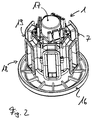
- FIG. 1 shows an insulating body 1 molded from plastic shown.
- the insulating body is cylindrical in the form of a not shown rotor surrounding an electrical machine
- the sleeve designs and has recesses 2 in its wall for the use shown in Figure 3 pole piece 3.
- the insulating body is 1st constructed in two parts from two halves (half shells) 4 and 5, which are assembled in the axial direction at the joint 6 are.
- On the outer jacket of the insulating body 1 are frame-shaped Brackets 7 formed, which surround the recesses 2.
- the brackets 7 are provided with collars 8, which are axial Limitation of the stator windings, not shown, on the holder are wound up.
- the cross section of the brackets 7, in particular the angle of the molded Collar 8, is designed so that the stator windings layered winding are supported.
- Both windings are thus through the connecting wire section 10 to the pair coupled.
- the wire section 10 is on the front side of the Insulating body 1 guided in guides 12 or around pin 13.
- the insulating body according to Figure 1 has in its end face a bore 22 which is suitable for receiving a bearing is.
- the remaining six wire ends 11 are in recordings 14 introduced on the front of the insulating body are arranged and in which insulation displacement contacts 15 are used.
- the insulation displacement contacts 15 serve on the one hand for fixing the wire ends 11 and on the other hand for external contact.
- the insulating body 1 shown in Figure 2 forms the complete Can of a can engine, for example one Heating pump that has a hydraulic separation between the Stator and the rotor manufactures.
- Components described has the insulating body 1 on its an end face a molded bearing plate 16 and its other end face a receptacle 17 for a plain bearing on.
- the insulating body is 1 in two parts.
- One part 18 is with the can molded bearing debt 16 and 17 formed
- the other part 19 is a ring that holds the remaining halves the frame 7 carries and which can be pushed onto the part 19.
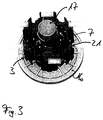
- FIG. 3 the insulating body according to Figure 2 is with inserted pole legs 3 shown. Clearly visible are the poles of the pole legs 3 opposite Foot areas that are provided with a dovetail 21. After the pole limbs 3 have been wound, this is shown in FIG shown package in a pole ring, not shown corresponding guides pressed.
- the process for producing a stator package for a electrical machine runs with the following steps. First, the pole pieces 3 are inserted into the recesses 2 of the insulating body 1, in particular a part of the Insulating body 1 used. Then the second part of the Insulator 1 placed and the pole piece directly or the holders 7 wrapped with flyer windings. Last will this package is pressed into the pole ring.
Abstract
Description
Die Erfindung betrifft einen Elektromotor, insbesondere zum Betrieb einer Pumpe, mit einem Stator, der von Wicklungen umgebene Polschenkel aufweist, und mit einem Polring, der die Polschenkel umgibt und an den die Polschenkel lösbar befestigt sind. Die Erfindung betrifft gleichfalls ein Verfahren zur Herstellung des Statorpaketes eines derartigen Elektromotors.The invention relates to an electric motor, in particular for Operation of a pump, with a stator by windings has surrounding pole pieces, and with a pole ring, the Surrounds pole piece and to which the pole piece can be detached are attached. The invention also relates to Method for producing the stator package of such a Electric motor.
Generell sind Elektromotoren bekannt, die einen Polring mit angeformten Polschenkeln aufweisen, wobei der Polring in eine der Anzahl der Polschenkel entsprechende Zahl von Segmenten aufgeteilt sein kann. Da Polring und Polschenkel eine Einheit bilden, müssen derartige aus Polring und Polschenkeln bestehende Statorpakete mit sogenannten Nadelwicklern bewickelt werden. Dabei werden Nadeln von einer Stirnseite des Statorpaketes zwischen die Polschenkel geführt und dabei der Draht um einen Polachenkel gelegt. Diese Art des Wickelns hat den Nachteil, daß die Windungen des Drahtes innerhalb der Wicklung eine große Zahl von Kreuzungspunkten aufweisen, was zu einer entsprechend geminderten Packungsdichte und damit zur Vergrößerung der Wicklungslänge (mittlere Spulenlänge) führt. Gleichzeitig erhöht die entsprechend größere Länge des Wickeldrahtes die Herstellungskosten des Motors, was gerade bei kleinen Motoren besonders ins Gewicht fällt.Electric motors are generally known which have a pole ring have molded pole legs, the pole ring in a number of segments corresponding to the number of pole legs can be divided. Since the pole ring and pole leg are one must form such from pole ring and pole legs existing stator packages with so-called needle winders be wound. Doing so will needles from one face of the stator package between the pole legs and thereby the wire is placed around a polar arm. This way of wrapping has the disadvantage that the turns of the wire within the Winding have a large number of crossing points what to a correspondingly reduced packing density and thus to increase the winding length (average coil length) leads. At the same time, the correspondingly greater length of the Winding wire the manufacturing cost of the motor what just is particularly important for small engines.
Bei größeren Motoren ist es bekannt, die Polschenkel einzeln mit Spulenwicklern zu wickeln und sie im gewickelten Zustand im Inneren des Polringes zu verschrauben. Diese Methode ist aufwendig und teuer, da manuelle Fertigungsschritte notwendig sind. Polschenkel im Polring zu verschrauben ist bei der Fertigung von kleinen Motoren zwischen 100 und 1000 Watt, die in Serie massenweise hergestellt werden, nicht praktikabel.With larger motors it is known to individually separate the pole legs to wind with coil winders and they in the wound state to screw inside the pole ring. This method is complex and expensive, since manual production steps are necessary are. The pole piece is screwed into the pole ring at the Manufacture of small motors between 100 and 1000 watts mass-produced in series, not practical.
Aufgabe der vorliegenden Erfindung ist es daher, eine elektrische Maschine, insbesondere einen Elektromotor, zu schaffen, dessen Statorpaket sich bei geringer Baugröße und großem Wirkungsgrad einfach und kostengünstig maschinell fertigen läßt. Gleichzeitig ist es Aufgabe der Erfindung ein Verfahren zur Herstellung eines Statorpaketes des erfindungsgemäßen Motors zu schaffen.The object of the present invention is therefore a electrical machine, in particular an electric motor create, the stator package with small size and high efficiency simple and inexpensive by machine can be made. At the same time, it is an object of the invention Method for producing a stator package of the To create motor according to the invention.
Diese Aufgabe wird durch eine elektrische Maschine nach
Anspruch 1 und ein Verfahren nach Anspruch 13 gelöst.This task is accomplished by an
Der Kern der Erfindung ist, daß alle Polschenkel von einem gemeinsamen als Polschenkelträger ausgebildeten Isolierkörper gehalten werden, der nach der Montage der Polschenkel im Statorpaket und damit in der elektrischen Maschine insbesondere dem Elektromotor verbleibt. Dieser Isolierkörper bietet insofern große Vorteile bei der Fertigung der Motoren, als nunmehr zunächst die einzelnen Polschenkel von Spulenwicklern, insbesondere von speziell für ein lagenweises Wickeln geeigneten Flyerwicklern, bewickelt werden können, bevor das Paket der vom Isolierkörper gehaltenen Polschenkel als Ganzes in den Polring eingesetzt wird. Die Bewickelung durch Flyerwickler ist im Gegensatz zu den bekannten Nadelwicklern besonders vorteilhaft, da sich die Wicklungen lagenweise und ohne Kreuzungen aufbringen lassen, so daß eine kompakte Wicklung mit geringer Auftragung entsteht. Außerdem ist es möglich mit großen Drahtquerschnitten zu wickeln, so daß die Wicklungen für hohe Ströme ausgelegt werden können.The essence of the invention is that all pole legs of one common insulating body designed as a pole piece support are kept in the after mounting the pole piece in Stator package and thus in the electrical machine especially the electric motor remains. This insulating body offers great advantages in the manufacture of motors, than now the individual pole pieces of Coil winders, especially those specially designed for a layer Winding suitable flyer winders, can be wound, before the package of pole pieces held by the insulator is inserted as a whole into the pole ring. The wrapping by flyer winder is in contrast to the known Needle winders are particularly advantageous because the windings can be applied in layers and without crossings, so that a compact winding with low application results. Moreover it is possible to wrap with large wire cross sections, so that the windings can be designed for high currents.
Vorteilhafterweise ist der erfindungsgemäße Isolierkörper als eine den Rotor vollständig umgebende und insbesondere aus Kunststoff gespritzte Hülse ausgebildet, die in ihrer Wandung Ausnehmungen zum Einstecken oder Einschieben der einzelnen Polschenkel aufweist. Durch die Hülse sind, die Polschenkel in der richtigen Lage gehalten, wobei die zu bewickelnden Sockel, die Wicklungsabschnitte, der Polschenkel radial von der Außenfläche des Mantels abstehen. Die Lagerung in dem hülsenförmigen Isolierkörper gewährleistet einerseits einen guten Zugang der wickelmaschine zu den Wicklungsabschnitten und richtet andererseits die Polschenkel in der richtigen Lage für den späteren Einbau aus. Das Einbringen der Polschenkel in den Isolierkörper ist dabei besonders einfach, wenn dieser aus zwei axial zusammenfügbaren Halbschalen aufgebaut ist. Dann können die Polschenkel in die eine Halbschale eingesetzt werden, bevor die andere Halbschale zur endgültigen Halterung der Polschenkel aufgesetzt wird.The insulating body according to the invention is advantageously as a completely surrounding and in particular from the rotor Plastic molded sleeve formed in its wall Recesses for inserting or inserting the individual Has pole piece. Through the sleeve, the pole pieces are in kept in the correct position, being wound Base, the winding sections, the pole leg radially from protrude from the outer surface of the jacket. Storage in the sleeve-shaped insulating body ensures one hand good access for the winding machine to the winding sections and on the other hand aligns the pole legs in the right one Location for later installation. Introducing the Pole leg in the insulating body is particularly simple, if this consists of two axially joinable half shells is constructed. Then the pole legs can be inserted in one Half shell are used before the other half shell final mounting of the pole piece is placed.
In einer weiteren vorteilhaften Ausführungsform der Isolierkörper sind an dessen dem Rotor abgewandten Außenseite rahmenförmige die Polschenkel umgebende Halterungen vorgesehen. Diese Halterungen sind so konzipiert, daß sie die Wicklungsabschnitte der Polschenkel einfassen und Schablonen bilden, auf die die Statorwicklungen aufwickelbar sind. Vorteilhafterweise ist der Isolierkörper mit den Halterungen einteilig aus Kunststoff gespritzt. Damit ist einerseits die kostengünstige Herstellung der Isolierkörper gewährleistet, während andererseits die mit abgerundeten Ecken und Kanten versehenen Kunststoffbauteile den Wicklungsdrähten einen guten Schutz vor Abrieb der Isolierung bieten.In a further advantageous embodiment of the Insulating bodies are on the outside facing away from the rotor frame-shaped brackets surrounding the pole legs intended. These brackets are designed to be the Border the winding sections of the pole legs and templates form on which the stator windings can be wound. The insulating body with the holders is advantageously molded in one piece from plastic. On the one hand, this is the ensures cost-effective production of the insulating body, while on the other hand those with rounded corners and edges provided plastic components the winding wires one provide good protection against abrasion of the insulation.
In einer vorteilhaften Ausführungsform hat der Isolierkörper zusätzliche Funktionen. So können beispielsweise an einer Stirnseite Aufnahmeteile vorgesehen werden, in die Schneid-Klemm-Kontakte zur Kontaktierung der Statorwicklungen einsetzbar sind. Die Aufnahmeteile können dabei angespritzt oder aufsteckbar sein. Die so geschaffenen Steckkontakte gewährleisten eine vollständig automatische Montage aller Komponenten in axialer Richtung. Zudem kann der Isolierkörper weitere Komponenten zur Optimierung der Führung und Kontaktierung der Wicklungsenden aufweisen. Der Isolierkörper kann auch Mittel zur Aufnahme eines Lagers für die Welle aufweisen. Er kann außerdem auf einen Spalttopf aufschiebbar oder sogar selber als Spalttopf für einen Spalttopfmotor ausgebildet sein. In dieser Form kann an einer Stirnseite ein Lagerschild und an der anderen Stirnseite eine Aufnahme für ein Gleitlager vorgesehen sein.In an advantageous embodiment, the insulating body additional functions. For example, on one Front receiving parts are provided in the insulation displacement contacts for contacting the stator windings can be used. The receiving parts can be injection molded or be attachable. The plug contacts created in this way ensure a fully automatic assembly of all Components in the axial direction. In addition, the insulating body other components to optimize the leadership and Have contacting of the winding ends. The insulating body can also include means for receiving a bearing for the shaft exhibit. It can also be pushed onto a can or even as a can for a can motor be trained. In this form, one can be on one end Bearing plate and on the other face a receptacle for a plain bearing may be provided.
Aus der großen Packungsdichte ergibt sich der Vorteil einer kleineren Baugröße der Motoren bei geringeren Fertigungs- und Materialkosten und höherem Wirkungsgrad wegen der geringeren benötigten Drahtlänge. Die erhöhte Packungsdichte reduziert gleichfalls die Gefahr des Entstehens von Geräuschen in der Wicklung. Außerdem wird durch die große Packungsdichte die Menge der eingeschlossenen Luft und damit die Gefahr elektrochemischer Korrosion reduziert. Das geht einher mit einer höheren Isolationsfestigkeit und einer besseren Wärmeabfuhr.The advantage of one comes from the high packing density smaller size of the motors with lower manufacturing and Material costs and higher efficiency because of the lower required wire length. The increased packing density is reduced likewise the risk of noise in the Winding. In addition, the high packing density Amount of trapped air and therefore the danger electrochemical corrosion reduced. That goes along with it higher insulation strength and better Heat dissipation.
Ein weiterer sehr großer Vorteil ist, daß insbesondere bei Mehrphasensystemen wie Drehstrommaschinen jeweils Paare von gegenüberliegenden Wicklungen mit einem durchgehenden Draht gewickelt werden können, so daß auf eine Kontaktverbindung zwischen den beiden Wicklungen eines Paares verzichtet werden kann. Durch das endlose Bewickeln eines Spulenpaares werden die Hälfte aller Wicklungsenden vermieden, was zu einer beträchtlichen Vereinfachung in der Produktion und, mit der zusätzlichen Ersparnis der Kontaktelemente, zu einer Reduzierung der Kosten führt. Durch den Einsatz des von Außen an den Isolierkörper herangeführten Flyerwicklers ist jedoch jede beliebige andere Systematik der Bewicklung der radial vom Isolierkörper nach Außen ragenden Wicklungsabschnitte der Polschenkel möglich.Another very great advantage is that in particular Multi-phase systems such as three-phase machines each have pairs of opposite windings with a continuous wire can be wound so that on a contact connection between the two windings of a pair can. By endlessly winding a pair of coils half of all winding ends avoided, resulting in a considerable simplification in production and, with that additional savings of the contact elements, to a Reduction of costs leads. By using the outside flyer winder brought up to the insulator any other system of winding the radial from the insulating body protruding winding sections of the Pole leg possible.
In einer besonders vorteihaften Ausführungsform werden der
Polring und die Polschenkel in der Technik des sogenannten
![]()
![]()
Im Falle der Statorpakete können auf diese Art Polringe und Polschenkel gefertigt werden, die mit sehr präzisen Linearführungen ansgestattet sind. Die Toleranzen der Führungen lassen sich dabei so dimensionieren, daß die Polschenkel in den Polring dauerhaft eingepreßt werden können, wobei der Luftspalt zwischen dem Polring und dem Fuß eines Polschenkels eine Weite von wenigen Mikrometern aufweist. Dieser Luftspalt ist im Verhältnis zum Luftspalt zwischen dem Rotor und dem Stator zu klein, als daß er den magnetischen Fluß zum Polring beeinträchtigen könnte. Auch wenn die erfindungsgemäßen Statoren in allen elektrischen Maschinen einsetzbar sind, so ist es besonders vorteilhaft, die erfindungsgemäßen Statorpakete bei Lüftermotoren oder bei Spaltrohrmotoren vorzusehen, die insbesondere in Kreiselpumpen für Heiz- oder Kühlsysteme eingesetzt werden.In the case of the stator packs, pole rings and Pole legs are made with very precise Linear guides are allowed. The tolerances of the Guides can be dimensioned so that the Pole legs are permanently pressed into the pole ring can, the air gap between the pole ring and the foot of a pole leg a width of a few micrometers having. This air gap is in relation to the air gap between the rotor and the stator too small to be the could affect magnetic flux to the pole ring. Also if the stators according to the invention in all electrical Machines can be used, it is particularly advantageous the stator packages according to the invention in fan motors or at Provide canned motors, which in particular Centrifugal pumps can be used for heating or cooling systems.
Auch wenn Linearführungen beliebigen Querschnittes denkbar sind, so ist eine Schwalbenschwanzführung besonders vorteilhaft, weil sie einen formschlüssigen Halt in radialer und in Umfangsrichtung bietet und weit sie sich durch das Verfahren des Stanzpaketierens einfach mit solchen Toleranzen so herstellen läßt, daß sich das Schlittenteil gut auf oder in das Bett der Führung einpressen läßt. Dabei ist diese Art der Führung vergleichsweise unempfindlich gegenüber Fertigungstoleranzen.Even if linear guides of any cross section are conceivable a dovetail guide is special advantageous because it has a positive hold in radial and offers in the circumferential direction and far through the Process of punching packaging simply with such tolerances can be made so that the sled part well on or pressed into the bed of the guide. This is the type comparatively insensitive to leadership Manufacturing tolerances.
In einer vorteilhaften Ausführungsform sind die Polschenkel in den Polring mittels einer axial angeordneten Linearführung, insbesondere einer Schwalbenschwanzführung, einsteckbar, wobei es besonders vorteilhaft ist, die Linearführung so auszubilden, daß die Polschenkel als im Isolierkörper zusammengefaßtes Paket in die Führungsnuten einpreßbar sind. Da das Einpressen vollständig maschinell geschehen kann, ist eine einfache und kostengünstige Fertigung gewährleistet.In an advantageous embodiment, the pole legs are in the pole ring by means of an axially arranged Linear guide, especially a dovetail guide, insertable, it being particularly advantageous that Train linear guide so that the pole legs as in Insulated package bundled in the guide grooves can be pressed in. Since the pressing is completely automated can happen is a simple and inexpensive Manufacturing guaranteed.
Eine Ausführungsform eines erfindungsgemäßen Statorpaketes ist in den Zeichnungen 1 und 2 dargestellt und wird im folgenden näher beschrieben. Es zeigen
-
Figur 1 - einen für die Aufnahme eines Lagers oder für das Aufsetzen auf einen Spalttopf geeigneten Isolierkörper,
-
Figur 2 - einen als Spalttopf ausgebildeten Isolierkörper und
-
Figur 3 - einen Isolierkörper mit eingesetzten Polschenkeln.
- Figure 1
- an insulating body suitable for accommodating a bearing or for placing on a containment shell,
- Figure 2
- an insulating body designed as a containment shell and
- Figure 3
- an insulating body with inserted pole legs.
In Figur 1 ist ein aus Kunststoff gespritzter Isolierkörper 1
gezeigt. Der Isolierkörper ist zylindrisch in Form einer den
nicht gezeigten Rotor einer elektrischen Maschine umgebenden
Hülse gestaltet und weist in seiner Wandung Ausnehmungen 2
für den Einsatz in Figur 3 dargestellter Polschenkel 3 auf.
In diesem Ausführungsbeispiel ist der Isolierkörper 1
zweiteilig aus zwei Hälften (Halbschalen) 4 und 5 aufgebaut,
die in axialer Richtung an der Stoßstelle 6 zusammengesetzt
sind. Am Außenmantel des Isolierkörpers 1 sind rahmenförmige
Halterungen 7 angeformt, welche die Ausnehmungen 2 umgeben.
Die Halterungen 7 sind mit Kragen 8 versehen, die eine axiale
Begrenzung der nicht dargestellten Statorwicklungen, die auf
die Halterung aufgewickelt sind, bewirken. Der Querschnitt
der Halterungen 7, insbesondere die Winkel der angeformten
Kragen 8, ist so konzipiert, daß die Statorwicklungen bei
lagenweiser Wicklung unterstützt werden.FIG. 1 shows an insulating
In dieser Ausführungsform werden die insbesondere im Stanz-Paketierverfahren
hergestellten Polschenkel 3 in die
Aufnahmen 2 der einen Halbschale 4 eingeschoben bevor die
zweite Halbschale 5 aufgesetzt wird. Die beiden Halbschalen
sind dabei mit Rastverbindungen 9 aneinander gehalten. Nach
dem Einfassen der Polschenkel 3, deren Wicklungsabschnitte
von den Halterungen 7 umgeben sind, werden diese von
Flyerwicklern bewickelt. In den Figuren sind die Wicklungen
nicht dargestellt, sondern lediglich die Wicklungsenden 11
gezeigt. In diesem Beispiel sind je zwei gegenüberliegende
der sechs Wicklungen zu einem Wicklungspaar zusammengefaßt.
Die Bewicklung eines Paares wird dabei derart vorgenommen,
daß zunächst eine der Wicklungen angefertigt wird, bevor der
Flyerkopf unter Mitnahme des Drahtes über die Stirnseite des
Isolierkörpers zur gegenüberliegenden Halterung wechselt und
dort die zweite Wicklung aufbringt. Beide Wicklungen sind
somit durch den verbindenden Drahtabschnitt 10 zu dem Paar
gekoppelt. Der Drahtabschnitt 10 wird auf der Stirnseite des
Isolierkörpers 1 in Führungen 12 oder um Zapfen 13 geführt.
Der Isolierkörper nach Figur 1 weist in seiner Stirnseite
eine Bohrung 22 auf, die zur Aufnahme eines Lagers geeignet
ist.In this embodiment, they are used in particular in the stamping / packaging method
manufactured
Die verbleibenden sechs Drahtenden 11 werden in Aufnahmen 14
eingebracht, die auf der Stirnseite des Isolierkörpers
angeordnet sind und in denen Schneid-Klemm-Kontakte 15
eingesetzt sind. Die Schneid-Klemm-Kontakte 15 dienen
einerseits zur Fixierung der Drahtenden 11 und andererseits
zur Kontaktierung nach Außen.The remaining six wire ends 11 are in
Der in Figur 2 gezeigte Isolierkörper 1 bildet den kopletten
Spalttopf eines Spalttopfmotors beispielsweise einer
Heizungspumpe, der eine hydraulische Trennung zwischen dem
Stator und dem Rotor herstellt. Neben den unter Figur 1
beschriebenen Komponenten weist der Isolierkörper 1 an seiner
einen Stirnseite einen angeformten Lagerschild 16 und an
seiner anderen Stirnseite eine Aufnahme 17 für ein Gleitlager
auf. Auch in diesem Beispiel ist der Isolierkörper 1
zweiteilig. Der eine Teil 18 wird von dem Spalttopf mit
angeformtem Lagerschuld 16 und Aufnahme 17 gebildet, der
andere Teil 19 ist ein Ring, der die verbleibenden Hälften
der Rahmen 7 trägt und der auf das Teil 19 aufschiebbar ist.
Dabei hält der Ring die am ersten Teil montierten
Polschenkel. Beide Teile 18 und 19 sind an dem Stoß 20
zusammengefügt.The insulating
In Figur 3 ist der Isolierkörper nach Figur 2 mit
eingesetzten Polschenkeln 3 gezeigt. Deutlich zu erkennen
sind die den Polen der Polschenkel 3 gegenüberliegenden
Fußbereiche, die mit einem Schwalbenschwanz 21 versehen sind.
Nach der Bewicklung der Polschenkel 3 wird das in Figur 3
gezeigte Paket in einen nicht dargestellten Polring mit
entsprechenden Führungen eingepreßt.In Figure 3, the insulating body according to Figure 2 is with
inserted
Das Verfahren zur Herstellung eines Statorpaketes für eine
elektrische Maschine läuft dabei mit folgenden Schritten ab.
Zunächst werden die die Polschenkel 3 in die Ausnehmungen 2
des Isolierkörpers 1, insbesondere eines Teiles des
Isolierkörpers 1 eingesetzt. Dann wird der zweite Teil des
Isolierkörpers 1 aufgesetzt und die Polschenkel direkt oder
die Halterungen 7 mit Flyerwicklungen umwickelt. Zuletzt wird
dieses Paket in den Polring eingepreßt.The process for producing a stator package for a
electrical machine runs with the following steps.
First, the
Claims (16)
dadurch gekennzeichnet, daß alle Polschenkel (3) in einem gemeinsamen Isolierkörper (1) gehalten sind, der nach der Montage der Polschenkel (3) im Statorpaket verbleibt.Electrical machine, in particular an electric motor for operating a fan or a pump, with a stator package which has pole legs surrounded by stator windings, the pole legs being surrounded by a pole ring to which the pole legs are detachably fastened,
characterized in that all pole legs (3) are held in a common insulating body (1) which remains in the stator package after the pole legs (3) have been installed.
dadurch gekennzeichnet, daß die Polschenkel (3) jeweils über eine axial angeordnete Linearführung (21), insbesondere über eine Schwalbenschwanzführung, mit dem Polring (3) in axialer Richtung kraftschlüssig und in Umfangsrichtung formschlüssig verbindbar sind.Machine according to claim 1,
characterized in that the pole legs (3) are each non-positively connected to the pole ring (3) in the axial direction and positively in the circumferential direction via an axially arranged linear guide (21), in particular via a dovetail guide.
dadurch gekennzeichnet,daß der Isolierkörper (1) eine den Rotor vollständig umgebende, insbesondere aus Kunststoff gespritzte, Hülse aufweist.Machine according to claim 1 or 2,
characterized in that the insulating body (1) has a sleeve completely surrounding the rotor, in particular molded from plastic.
dadurch gekennzeichnet, daß der Isolierkörper (1) Ausnehmungen (2) zur Aufnahme der Polschenkel (3) aufweist.Machine according to one of the preceding claims,
characterized in that the insulating body (1) has recesses (2) for receiving the pole legs (3).
dadurch gekennzeichnet,daß der Isolierkörper (1) aus zwei axial zusammenfügbaren Halbschalen aufgebaut ist. Machine according to one of the preceding claims,
characterized in that the insulating body (1) is constructed from two axially joinable half-shells.
dadurch gekennzeichnet,daß der Isolierkörper (1) an seiner dem Rotor abgewandten Außenseite rahmenförmige, die Polschenkel umgebende Halterungen (7) aufweist, auf welche die Statorwicklungen aufwickelbar sind.Machine according to one of the preceding claims,
characterized in that the insulating body (1) has on its outer side facing away from the rotor frame-shaped holders (7) surrounding the pole limbs, on which the stator windings can be wound.
dadurch gekennzeichnet,daß der Isolierkörper (1) und die Halterungen (7) einteilig aus Kunststoff gespritzt sind.Machine according to claim 6,
characterized in that the insulating body (1) and the holders (7) are injection-molded in one piece from plastic.
dadurch gekennzeichnet,daß der Isolierkörper (1) auf einer Stirnseite Aufnahmen (14) aufweist, in die Schneid-Klemm-Kontakte (15) zur Kontaktierung der Statorwicklungen einsetzbar sind.Machine according to one of the preceding claims,
characterized in that the insulating body (1) has receptacles (14) on one end face, into which insulation displacement contacts (15) can be inserted for contacting the stator windings.
dadurch gekennzeichnet,daß der Isolierkörper (1) einen Spalttopf zwischen dem Stator und dem Rotor bildet.Machine according to one of the preceding claims,
characterized in that the insulating body (1) forms a containment shell between the stator and the rotor.
dadurch gekennzeichnet,daß der Isolierkörper (1) einen Lagerträger (22) für den Halt eines Lagers der Welle aufweist.Machine according to one of the preceding claims,
characterized in that the insulating body (1) has a bearing bracket (22) for holding a bearing of the shaft.
dadurch gekennzeichnet,daß Statorwicklungen zu Wicklungspaaren zusammengefaßt sind, wobei ein Wicklungspaar aus einem endlosen Draht gewickelt ist.Machine according to one of the preceding claims,
characterized in that stator windings are combined into pairs of windings, one pair of windings being wound from an endless wire.
dadurch gekennzeichnet, daß die Statorwicklungen lagenweise gewickelt sind. Machine according to one of the preceding claims,
characterized in that the stator windings are wound in layers.
dadurch gekennzeichnet,daß die Polschenkel (3) und der Polring durch Aufeinanderlegen einzelner Bleche im Stanzpaketierverfahren hergestellt sind.Machine according to one of the preceding claims,
characterized in that the pole limbs (3) and the pole ring are produced by stacking individual sheets on one another in the stamped packet-packing process.
dadurch gekennzeichnet,
characterized by
dadurch gekennzeichnet,
daß die Polschenkel (3) in die Linearführungen (21) des Polringes eingepreßt werden.The method of claim 14
characterized by
that the pole legs (3) are pressed into the linear guides (21) of the pole ring.
dadurch gekennzeichnet,
daß die Enden der Wicklungen (11) zu den stirnseitig vorgesehenen Aufnahmen (14) geführt und mit einem Schneid-Klemm-Kontakt (15) versehen werden.A method according to claim 14 or 15,
characterized by
that the ends of the windings (11) are guided to the receptacles (14) provided on the end face and are provided with an insulation displacement contact (15).
Applications Claiming Priority (2)
| Application Number | Priority Date | Filing Date | Title |
|---|---|---|---|
| DE19905948 | 1999-02-12 | ||
| DE1999105948 DE19905948A1 (en) | 1999-02-12 | 1999-02-12 | Pole piece carrier |
Publications (3)
| Publication Number | Publication Date |
|---|---|
| EP1028513A2 true EP1028513A2 (en) | 2000-08-16 |
| EP1028513A3 EP1028513A3 (en) | 2000-12-20 |
| EP1028513B1 EP1028513B1 (en) | 2008-05-28 |
Family
ID=7897340
Family Applications (1)
| Application Number | Title | Priority Date | Filing Date |
|---|---|---|---|
| EP20000102552 Expired - Lifetime EP1028513B1 (en) | 1999-02-12 | 2000-02-07 | Salient poles support |
Country Status (2)
| Country | Link |
|---|---|
| EP (1) | EP1028513B1 (en) |
| DE (2) | DE19905948A1 (en) |
Cited By (3)
| Publication number | Priority date | Publication date | Assignee | Title |
|---|---|---|---|---|
| EP1347556A2 (en) * | 2002-03-21 | 2003-09-24 | Robert Bosch Gmbh | Stator of rotary electrical machine |
| EP1499000A1 (en) * | 2003-07-12 | 2005-01-19 | Grundfos a/s | Segmented stator |
| WO2009127525A1 (en) * | 2008-04-18 | 2009-10-22 | Continental Automotive Gmbh | Insulation support for a stator of an electric motor for driving liquid pumps |
Families Citing this family (1)
| Publication number | Priority date | Publication date | Assignee | Title |
|---|---|---|---|---|
| DE202014005789U1 (en) | 2014-07-17 | 2015-10-23 | Brose Fahrzeugteile Gmbh & Co. Kommanditgesellschaft, Coburg | Stator of an electric motor and contact system for this |
Citations (5)
| Publication number | Priority date | Publication date | Assignee | Title |
|---|---|---|---|---|
| EP0064105A1 (en) * | 1981-05-06 | 1982-11-10 | AMP INCORPORATED (a New Jersey corporation) | Electric motor stator and a method of manufacturing the stator |
| US4818911A (en) * | 1985-03-09 | 1989-04-04 | Asmo Co., Ltd. | Stator of electric motor |
| EP0374612A1 (en) * | 1988-12-23 | 1990-06-27 | WILO GmbH | Gap tube electric motor |
| JPH0775270A (en) * | 1993-09-03 | 1995-03-17 | Canon Electron Inc | Rotating magnetic field generating unit for electromagnetic rotary apparatus |
| EP0910152A1 (en) * | 1997-10-16 | 1999-04-21 | Bitron S.p.A. | A stator for electric motors with an electrically insulating co-moulded covering |
Family Cites Families (2)
| Publication number | Priority date | Publication date | Assignee | Title |
|---|---|---|---|---|
| DE19740937A1 (en) * | 1997-09-17 | 1999-03-18 | Trw Fahrzeugelektrik | Procedure for winding stator for brushless DC motor e.g. for hydraulic power steering pump of vehicle |
| DE19740938A1 (en) * | 1997-09-17 | 1999-03-18 | Trw Fahrzeugelektrik | Stator for electric motor, especially brushless DC motor |
-
1999
- 1999-02-12 DE DE1999105948 patent/DE19905948A1/en not_active Withdrawn
-
2000
- 2000-02-07 EP EP20000102552 patent/EP1028513B1/en not_active Expired - Lifetime
- 2000-02-07 DE DE50015176T patent/DE50015176D1/en not_active Expired - Lifetime
Patent Citations (5)
| Publication number | Priority date | Publication date | Assignee | Title |
|---|---|---|---|---|
| EP0064105A1 (en) * | 1981-05-06 | 1982-11-10 | AMP INCORPORATED (a New Jersey corporation) | Electric motor stator and a method of manufacturing the stator |
| US4818911A (en) * | 1985-03-09 | 1989-04-04 | Asmo Co., Ltd. | Stator of electric motor |
| EP0374612A1 (en) * | 1988-12-23 | 1990-06-27 | WILO GmbH | Gap tube electric motor |
| JPH0775270A (en) * | 1993-09-03 | 1995-03-17 | Canon Electron Inc | Rotating magnetic field generating unit for electromagnetic rotary apparatus |
| EP0910152A1 (en) * | 1997-10-16 | 1999-04-21 | Bitron S.p.A. | A stator for electric motors with an electrically insulating co-moulded covering |
Non-Patent Citations (1)
| Title |
|---|
| PATENT ABSTRACTS OF JAPAN vol. 1995, no. 06, 31. Juli 1995 (1995-07-31) & JP 07 075270 A (CANON ELECTRON INC), 17. März 1995 (1995-03-17) * |
Cited By (4)
| Publication number | Priority date | Publication date | Assignee | Title |
|---|---|---|---|---|
| EP1347556A2 (en) * | 2002-03-21 | 2003-09-24 | Robert Bosch Gmbh | Stator of rotary electrical machine |
| EP1347556A3 (en) * | 2002-03-21 | 2005-11-30 | Robert Bosch Gmbh | Stator of rotary electrical machine |
| EP1499000A1 (en) * | 2003-07-12 | 2005-01-19 | Grundfos a/s | Segmented stator |
| WO2009127525A1 (en) * | 2008-04-18 | 2009-10-22 | Continental Automotive Gmbh | Insulation support for a stator of an electric motor for driving liquid pumps |
Also Published As
| Publication number | Publication date |
|---|---|
| EP1028513B1 (en) | 2008-05-28 |
| DE19905948A1 (en) | 2000-08-17 |
| DE50015176D1 (en) | 2008-07-10 |
| EP1028513A3 (en) | 2000-12-20 |
Similar Documents
| Publication | Publication Date | Title |
|---|---|---|
| DE112008002806B4 (en) | Rotating electrical machine | |
| DE2244806C2 (en) | Dynamo-electric machine | |
| DE19643561C1 (en) | Electrical machine with single pole winding | |
| DE10160011B4 (en) | Stand construction of a piston engine | |
| DE102016224526A1 (en) | Stator of an electric machine, electric machine and laying and contact device for an electric machine | |
| DE112004001908T5 (en) | Anchor of a rotating electrical machine and its manufacturing process | |
| DE112011100325T5 (en) | Busbar unit and motor | |
| DE112005000816T5 (en) | Brushless motor | |
| DE102015212821A1 (en) | Stator assembly, rotary electric machine and method of manufacturing a stator assembly | |
| DE102010064051A1 (en) | Winding carrier for the isolation of a single-tooth winding in electrical machines | |
| DE102006025778A1 (en) | Method for producing a stator and associated stator | |
| EP1014536A2 (en) | Statorbundle with insertable salient poles | |
| DE112008002752T5 (en) | Stator and rotating electrical machine | |
| DE102009010475A1 (en) | Winding fixing component and rotary electric machine equipped therewith | |
| WO2018192817A1 (en) | Pole tooth module for an electric machine, active part comprising a pole tooth module, and electric machine | |
| DE19503610C2 (en) | Multi-phase and multi-pole, electrically commutatable machine and method for manufacturing the stand | |
| DE202014005789U1 (en) | Stator of an electric motor and contact system for this | |
| DE102016114829A1 (en) | Engine and method of making a motor | |
| DE112016005116T5 (en) | WINDING AND STATOR ARRANGEMENT OF AN ELECTROROTORING MACHINE | |
| EP3488516B1 (en) | Stator of an alternating current machine | |
| EP1041697B1 (en) | Reluctance machine with at least two salient poles each having an exciter coil and method for manufacturing the stator of such a machine | |
| DE112013001643T5 (en) | Electric rotating machine | |
| EP1024581B1 (en) | Motor winding connections | |
| DE102020115642B3 (en) | Electric motor and circuit board | |
| DE112018001742T5 (en) | ENGINE |
Legal Events
| Date | Code | Title | Description |
|---|---|---|---|
| PUAI | Public reference made under article 153(3) epc to a published international application that has entered the european phase |
Free format text: ORIGINAL CODE: 0009012 |
|
| AK | Designated contracting states |
Kind code of ref document: A2 Designated state(s): DE FR GB IT |
|
| AX | Request for extension of the european patent |
Free format text: AL;LT;LV;MK;RO;SI |
|
| PUAL | Search report despatched |
Free format text: ORIGINAL CODE: 0009013 |
|
| AK | Designated contracting states |
Kind code of ref document: A3 Designated state(s): AT BE CH CY DE DK ES FI FR GB GR IE IT LI LU MC NL PT SE |
|
| AX | Request for extension of the european patent |
Free format text: AL;LT;LV;MK;RO;SI |
|
| 17P | Request for examination filed |
Effective date: 20010620 |
|
| AKX | Designation fees paid |
Free format text: DE FR GB IT |
|
| RAP1 | Party data changed (applicant data changed or rights of an application transferred) |
Owner name: WILO AG |
|
| GRAP | Despatch of communication of intention to grant a patent |
Free format text: ORIGINAL CODE: EPIDOSNIGR1 |
|
| RIN1 | Information on inventor provided before grant (corrected) |
Inventor name: SCHRECKENBERG, STEPHAN Inventor name: GENSTER, ALBERT Inventor name: KECH, HANSJUERGEN Inventor name: LUETKENHAUS, NORBERT |
|
| GRAS | Grant fee paid |
Free format text: ORIGINAL CODE: EPIDOSNIGR3 |
|
| GRAA | (expected) grant |
Free format text: ORIGINAL CODE: 0009210 |
|
| AK | Designated contracting states |
Kind code of ref document: B1 Designated state(s): DE FR GB IT |
|
| REG | Reference to a national code |
Ref country code: GB Ref legal event code: FG4D Free format text: NOT ENGLISH |
|
| REF | Corresponds to: |
Ref document number: 50015176 Country of ref document: DE Date of ref document: 20080710 Kind code of ref document: P |
|
| PLBE | No opposition filed within time limit |
Free format text: ORIGINAL CODE: 0009261 |
|
| STAA | Information on the status of an ep patent application or granted ep patent |
Free format text: STATUS: NO OPPOSITION FILED WITHIN TIME LIMIT |
|
| 26N | No opposition filed |
Effective date: 20090303 |
|
| REG | Reference to a national code |
Ref country code: FR Ref legal event code: PLFP Year of fee payment: 16 |
|
| PGFP | Annual fee paid to national office [announced via postgrant information from national office to epo] |
Ref country code: DE Payment date: 20150203 Year of fee payment: 16 Ref country code: IT Payment date: 20150213 Year of fee payment: 16 |
|
| PGFP | Annual fee paid to national office [announced via postgrant information from national office to epo] |
Ref country code: FR Payment date: 20150210 Year of fee payment: 16 Ref country code: GB Payment date: 20150204 Year of fee payment: 16 |
|
| REG | Reference to a national code |
Ref country code: DE Ref legal event code: R119 Ref document number: 50015176 Country of ref document: DE |
|
| GBPC | Gb: european patent ceased through non-payment of renewal fee |
Effective date: 20160207 |
|
| REG | Reference to a national code |
Ref country code: FR Ref legal event code: ST Effective date: 20161028 |
|
| PG25 | Lapsed in a contracting state [announced via postgrant information from national office to epo] |
Ref country code: IT Free format text: LAPSE BECAUSE OF NON-PAYMENT OF DUE FEES Effective date: 20160207 |
|
| PG25 | Lapsed in a contracting state [announced via postgrant information from national office to epo] |
Ref country code: GB Free format text: LAPSE BECAUSE OF NON-PAYMENT OF DUE FEES Effective date: 20160207 Ref country code: FR Free format text: LAPSE BECAUSE OF NON-PAYMENT OF DUE FEES Effective date: 20160229 Ref country code: DE Free format text: LAPSE BECAUSE OF NON-PAYMENT OF DUE FEES Effective date: 20160901 |