EP1028273B1 - Differential gearing - Google Patents
Differential gearing Download PDFInfo
- Publication number
- EP1028273B1 EP1028273B1 EP00100294A EP00100294A EP1028273B1 EP 1028273 B1 EP1028273 B1 EP 1028273B1 EP 00100294 A EP00100294 A EP 00100294A EP 00100294 A EP00100294 A EP 00100294A EP 1028273 B1 EP1028273 B1 EP 1028273B1
- Authority
- EP
- European Patent Office
- Prior art keywords
- differential
- planet carrier
- bolt
- rotation
- bolts
- Prior art date
- Legal status (The legal status is an assumption and is not a legal conclusion. Google has not performed a legal analysis and makes no representation as to the accuracy of the status listed.)
- Expired - Lifetime
Links
Images
Classifications
-
- F—MECHANICAL ENGINEERING; LIGHTING; HEATING; WEAPONS; BLASTING
- F16—ENGINEERING ELEMENTS AND UNITS; GENERAL MEASURES FOR PRODUCING AND MAINTAINING EFFECTIVE FUNCTIONING OF MACHINES OR INSTALLATIONS; THERMAL INSULATION IN GENERAL
- F16H—GEARING
- F16H48/00—Differential gearings
- F16H48/06—Differential gearings with gears having orbital motion
- F16H48/08—Differential gearings with gears having orbital motion comprising bevel gears
- F16H2048/082—Differential gearings with gears having orbital motion comprising bevel gears characterised by the arrangement of output shafts
-
- F—MECHANICAL ENGINEERING; LIGHTING; HEATING; WEAPONS; BLASTING
- F16—ENGINEERING ELEMENTS AND UNITS; GENERAL MEASURES FOR PRODUCING AND MAINTAINING EFFECTIVE FUNCTIONING OF MACHINES OR INSTALLATIONS; THERMAL INSULATION IN GENERAL
- F16H—GEARING
- F16H48/00—Differential gearings
- F16H48/06—Differential gearings with gears having orbital motion
- F16H48/08—Differential gearings with gears having orbital motion comprising bevel gears
- F16H2048/085—Differential gearings with gears having orbital motion comprising bevel gears characterised by shafts or gear carriers for orbital gears
-
- F—MECHANICAL ENGINEERING; LIGHTING; HEATING; WEAPONS; BLASTING
- F16—ENGINEERING ELEMENTS AND UNITS; GENERAL MEASURES FOR PRODUCING AND MAINTAINING EFFECTIVE FUNCTIONING OF MACHINES OR INSTALLATIONS; THERMAL INSULATION IN GENERAL
- F16H—GEARING
- F16H48/00—Differential gearings
- F16H48/38—Constructional details
- F16H48/40—Constructional details characterised by features of the rotating cases
- F16H2048/405—Constructional details characterised by features of the rotating cases characterised by features of the bearing of the rotating case
-
- F—MECHANICAL ENGINEERING; LIGHTING; HEATING; WEAPONS; BLASTING
- F16—ENGINEERING ELEMENTS AND UNITS; GENERAL MEASURES FOR PRODUCING AND MAINTAINING EFFECTIVE FUNCTIONING OF MACHINES OR INSTALLATIONS; THERMAL INSULATION IN GENERAL
- F16H—GEARING
- F16H48/00—Differential gearings
- F16H48/38—Constructional details
- F16H48/40—Constructional details characterised by features of the rotating cases
Definitions
- the present invention relates to a differential with a planet carrier, a first bevel gear and a second bevel gear, each of which is relative to one another are rotatably arranged on a central axis of rotation, with at least three Differential wheels, which are in a perpendicular to the central axis of rotation and between the two bevel gears lying at a distance from each other around the central one Rotation axis are arranged around and the first and the second bevel gear couple with each other, with at least two bolts, each at one end are mounted on the planet carrier and on which the differential gears around their respective own axis of rotation are rotatably arranged.
- a differential is described in the generic DE18514260U.
- Generic transmissions are used, for example, in motor vehicles for transmission of torques used.
- the differential gear a main pin has, which is mounted on both ends of the planet carrier, and at least one Short bolt with one of its ends on at least one of the remaining bolts is stored.
- a favorable embodiment can result from the fact that the support element Has holes in which the short bolts can be inserted. This allows a quick one Assembly.
- the support element is spaced apart from the main bolt, ie is not supported on the main bolt. This enables the main bolt to be relieved.
- the differential gear of the present embodiment has a cup-shaped housing designed planet carrier 1.
- the planet carrier 1 is on one end via a bearing 2 and a cover 3 on a wall W of Gearbox rotatably mounted about a central axis of rotation Z.
- the opposite end of the planet carrier 1 has a central, circular Opening 4, which is closed by a flange 5.
- the flange 5 is via a bearing 6 and a cover 5a also on the transmission wall W around the central one Rotation axis Z rotatably mounted.
- a gear 7 concentric with the central axis of rotation Z. has an external toothing 7a, rotatably attached.
- a first bevel gear 8 concentric with the central axis of rotation Z added.
- Its side facing the flange 5 is conical Provide teeth 9.
- Its side facing camp 2 has one rotationally symmetrical shoulder 10. This is in a corresponding concentric Opening 11 of the planet carrier 1 added.
- the bevel gear 8 is rotatably fixed to the end of a shaft 20.
- the shaft 20 runs starting from the bevel gear 8 along the central axis of rotation Z and penetrates the cup-shaped planet carrier 1 in its bottom area and the lid 3. It is on their other end outside of the gearbox wall W of the gearbox in a rotationally fixed manner a coupling flange 21 connected.
- the bevel gear 8 in the direction of the bearing 6 opposite and also A second bevel gear 25 is provided concentrically with the central axis of rotation Z. Its side facing the bevel gear 8 has a conical toothing 26 Mistake. Its side facing the flange 5 has a rotationally symmetrical side Shoulder 27. This is in a corresponding concentric opening 28 of the Flange 5 added.
- the bevel gear 25 is non-rotatably connected to one end of a second shaft 30.
- the Shaft 30 extends from the bevel gear 25 along the central axis of rotation Z and penetrates the flange 5 and the lid 5a.
- On the bevel gear 25 opposite end is the shaft 30 with an outside of the wall W des Gearbox located coupling flange 31 rotatably connected.
- a main pin runs between the first bevel gear 8 and the second bevel gear 25 40 perpendicular through the central axis of rotation Z in a plane perpendicular to the central axis of rotation Z stands.
- This main pin 40 is in at one end an opening 41 of the planet carrier 1, which is approximately the same diameter as the Has bolt 40 added. Its opposite end is in a second Opening 42 of the planet carrier 1 is added, which is also approximately the same Diameter as the bolt 40 has.
- the main pin 40 has at this end also a vertical bore 43. Aligned with the bore 43 is in the planet carrier 1 a bore 44 is provided. By pressing a roll pin 45 into the Bores 43, 44, the main pin 40 is fixed to the planet carrier 1.
- the main pin 40 carries a block-shaped support element 50 axially in its center a through hole 51 is provided in the support member 50, in which the Main bolt 40 is received.
- a short bolt 61 is received on one side of this bore 52.
- a second Short bolt 62 is added.
- the short bolts 61, 62 have approximately the same Diameter like the bore 52. They run from the support element 50 perpendicular to the central axis of rotation Z and perpendicular to the main pin 40 for Planet carrier 1 out.
- the short pin 61 is in alignment with Opening 52 provided bore 63 in the planet carrier 1 added. He's like there the main pin 40 with a dowel pin 64 running perpendicular to the short pin 61 secured.
- the second short bolt 62 is also aligned with its second end Opening 52 provided bore 65 in the planet carrier 1 added. He is too fixed by means of a dowel pin 66.
- the bores 63, 64 have a diameter which corresponds approximately to the diameter of the short bolts 61, 62.
- the support element 50 is thus carried by the main pin 40. There is an axial fixation thereby by the engagement of the short bolts 61 and 62 in the bore 52 of the support element 50 guaranteed.
- the main pin 40 and the short pin 61 and 62 make four 90 each Shaft sections offset from one another in the plane between the bevel gears 8 and 25 formed.
- the differential gears have 67-70 concentric to theirs respective axis of rotation, a central bore that the respective bolt 40, 61, 62nd encloses.
- the differential gears 67-70 are mounted so that their teeth with which the bevel gears 8, 25 are engaged. As a result, the bevel gears 8, 25 are over each of the differential gears 67-70 coupled together.
- grooves 78 are provided in the bolts 40, 61, 62, which on the The bolt surface runs along the respective bolt 40, 61, 62.
- the operation of the differential gear corresponds to that of the generic type Differential and is as follows.
- the gear 7 is on its external teeth 7a applied with a torque. This torque is due to the non-rotating Transfer the screw connection to the flange 5 and the planet carrier 1.
- the bolts 40, 61, 62 mounted in the planet carrier 1 are taken along. about the teeth of the differential gears 67-70 with the bevel gears 8, 25 will Transfer torque to the bevel gears 8, 25.
- the support element 50 has enlarged bore 51 so that no support of the support member 50 on Main bolt 40 would be done. There is only a bypass of the main pin 40 instead, to the two short bolts 61 and 62 at their ends to each other connect and support each other. In this way, the main pin 40 relieved.
Abstract
Description
Die vorliegende Erfindung betrifft ein Ausgleichsgetriebe mit einem Planetenträger, einem ersten Kegelrad sowie einem zweiten Kegelrad, welche jeweils relativ zueinander drehbar auf einer zentralen Rotationsachse angeordnet sind, mit mindestens drei Ausgleichsrädern, welche in einer senkrecht zur zentralen Rotationsachse und zwischen den beiden Kegelrädern liegenden Ebene zueinander beabstandet um die zentrale Rotationsachse herum angeordnet sind und jeweils das erste und das zweite Kegelrad miteinander koppeln, mit mindestens zwei Bolzen, welche an ihrem einen Ende jeweils am Planetenträger gelagert sind und auf denen die Ausgleichsräder um ihre jeweilige eigene Rotationssachse drehbar angeordnet sind. Ein solchen Ausgleichgetriebe ist im gattungsgemäßen DE18514260U beschrieben.The present invention relates to a differential with a planet carrier, a first bevel gear and a second bevel gear, each of which is relative to one another are rotatably arranged on a central axis of rotation, with at least three Differential wheels, which are in a perpendicular to the central axis of rotation and between the two bevel gears lying at a distance from each other around the central one Rotation axis are arranged around and the first and the second bevel gear couple with each other, with at least two bolts, each at one end are mounted on the planet carrier and on which the differential gears around their respective own axis of rotation are rotatably arranged. Such a differential is described in the generic DE18514260U.
Gattungsgemäße Getriebe werden beispielsweise in Kraftfahrzeugen zur Übertragung von Drehmomenten eingesetzt.Generic transmissions are used, for example, in motor vehicles for transmission of torques used.
Es ist bekannt, solche Ausgleichsgetriebe mit zwei oder vier Ausgleichsrädern auszustatten. Weist das Ausgleichsgetriebe lediglich zwei Ausgleichsräder auf, so ist aufgrund der relativ starken punktuellen Belastung das gesamte Getriebe verhältnismäßig groß zu dimensionieren. Werden die Getriebe dagegen mit vier Ausgleichsrädem ausgestattet, so führt dies zu einem Überkreuzen der Bolzen, auf denen die Ausgleichsräder montiert werden. Um bei einer solchen Bauweise eine Montage zu ermöglichen, muß das Getriebe in der Ebene der überkreuzten Bolzen geteilt werden. Die dadurch erforderlichen Flanschränder und Verschraubungen führen ebenfalls zu einer eher großvolumigen Bauform.It is known such differential gear with two or four differential gears equip. If the differential has only two differential gears, then the entire gearbox due to the relatively high point load to be dimensioned relatively large. On the other hand, the gearboxes with four Equalization wheels equipped, this leads to a crossing of the bolts where the differential gears are mounted. In order to achieve such a design To allow assembly, the gearbox must be in the plane of the crossed bolts to be shared. Guide the flange edges and screw connections required also in a rather large-volume design.
Aus der DE 196 31 937 A1 ist bekannt, ein Ausgleichsgetriebe mit drei Ausgleichsrädern auszustatten. Dazu ist ein zentrales Tragstück vorgesehen, an dem drei Bolzen jeweils um 120 Grad zueinander versetzt in einer Ebene montiert sind. Jeder dieser Bolzen trägt ein Ausgleichsrad. Nachteilig ist dabei die aufwendige Verschraubung im Tragstück und die Gewährleistung der Sicherheit der Verschraubung trotz starker Vibrationen im Getriebe. DE 196 31 937 A1 discloses a differential gear with three differential gears equip. For this purpose, a central support piece is provided, on each of the three bolts mounted at 120 degrees to each other on one level. Each of these bolts carries a differential gear. The disadvantage is the complex screwing in the support piece and ensuring the security of the screw connection despite strong vibrations in the Transmission.
Es besteht deshalb das Problem, ein kompaktes und sicheres Getriebe zu gestalten.There is therefore the problem of designing a compact and safe gear.
Das Problem wird unter Hinzunahme der gattungsbildenden Merkmale des Oberbegriffes
des Anspruches 1 dadurch gelöst, daß das Ausgleichsgetriebe einen Hauptbolzen
besitzt, der an beiden seiner Enden am Planetenträger gelagert ist, und mindestens ein
Kurzbolzen, der mit einem seiner Enden an mindestens einem der übrigen Bolzen
gelagert ist.The problem is added with the generic features of the generic term
of
Es kann von Vorteil sein, wenn der Kurzbolzen am Hauptbolzen gelagert ist. Dadurch läßt sich eine einfache Montage erreichen.It can be advantageous if the short bolt is mounted on the main bolt. Thereby a simple assembly can be achieved.
Vorteile können sich dadurch ergeben, daß der Kurzbolzen an einem weiteren Kurzbolzen gelagert ist. Dadurch wird eine Überlastung des Hauptbolzens vermieden.Advantages can result from the fact that the short bolt on another Short bolt is stored. This prevents the main bolt from being overloaded.
Es ist möglicherweise sinnvoll, wenn zur Lagerung des bzw. der Kurzbolzen an einem anderen Bolzen ein Stützelement vorgesehen ist. Dadurch bleibt die Form der Kurzbolzen und somit ihre Fertigung einfach.It may make sense to store the short bolt (s) on one other bolts a support element is provided. This keeps the shape of the Short bolts and thus their production is simple.
Eine günstige Ausführungsform kann sich dadurch ergeben, daß das Stützelement Bohrungen besitzt, in welche die Kurzbolzen einsteckbar sind. Dies erlaubt eine schnelle Montage.A favorable embodiment can result from the fact that the support element Has holes in which the short bolts can be inserted. This allows a quick one Assembly.
Es kann zweckmäßig sein, wenn das Stützelement zum Hauptbolzen beabstandet, also nicht am Hauptbolzen abgestützt ist. Dies ermöglich eine Entlastung des Hauptbolzens.It may be expedient if the support element is spaced apart from the main bolt, ie is not supported on the main bolt. This enables the main bolt to be relieved.
Es kann zweckmäßig sein, wenn die am Planetenträger gelagerten Enden der Bolzen lösbar am Planetenträger befestigt sind. Dies erlaubt eine sichere Befestigung und eine spätere Demontage.It may be appropriate if the ends of the bolts mounted on the planet carrier are releasably attached to the planet carrier. This allows a secure attachment and a later disassembly.
Es kann von Vorteil sein, wenn zur Befestigung ein Spannstift vorgesehen ist. Dies stellt eine kostengünstige und zuverlässige Befestigung dar.It can be advantageous if a roll pin is provided for fastening. This poses an inexpensive and reliable attachment.
Details der Erfindung werden in der nachfolgenden Beschreibung, der lediglich beispielhafter Charakter zukommt, erläutert. Es wird dabei Bezug genommen auf:
- Fig. 1
- ein Längsschnitt durch ein Ausführungsbeispiel eines Ausgleichsgetriebes;
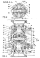
- Fig. 2
- ein Querschnitt entlang der Linie A-A von
Figur 1, wobei die Fig. 1 und 2 nicht vollumfänglich im Einklang mit dem Wortlaut desAnspruchs 1 stehen.
- Fig. 1
- a longitudinal section through an embodiment of a differential gear;
- Fig. 2
- a cross section along the line AA of Figure 1, wherein Figs. 1 and 2 are not fully in line with the wording of
claim 1.
Das Ausgleichsgetriebe der vorliegenden Ausführungsform besitzt einen als
becherartiges Gehäuse ausgestalteten Planetenträger 1. Der Planetenträger 1 ist an
seinem einen Ende über ein Lager 2 und einen Deckel 3 an einer Wandung W des
Getriebes um eine zentrale Rotationsachse Z drehbar gelagert.The differential gear of the present embodiment has a
cup-shaped housing designed
Das gegenüberliegende Ende des Planetenträgers 1 besitzt eine zentrale, kreisförmige
Öffnung 4, die durch einen Flansch 5 verschlossen ist. Der Flansch 5 ist über ein Lager 6
und einen Deckel 5a ebenfalls an der Getriebewandung W um die zentrale
Rotationsachse Z drehbar gelagert.The opposite end of the
Am Flansch 5 ist konzentrisch zur zentralen Rotationsachse Z ein Zahnrad 7, welches
eine Außenverzahnung 7a aufweist, drehfest angebracht. Im gehäuseförmigen
Planetenträger 1 ist ein erstes Kegelrad 8 konzentrisch zur zentralen Rotationsachse Z
aufgenommen. Seine zum Flansch 5 weisende Seite ist mit einer kegelförmigen
Verzahnung 9 versehen. Seine zum Lager 2 weisende Seite besitzt eine
rotationssymmetrische Schulter 10. Diese ist in einer korrespondierenden konzentrischen
Öffnung 11 des Planetenträgers 1 aufgenommen.On the
Das Kegelrad 8 ist drehfest am Ende einer Welle 20 befestigt. Die Welle 20 verläuft
ausgehend vom Kegelrad 8 entlang der zentralen Rotationsachse Z und durchdringt den
becherförmigen Planetenträger 1 in seinem Bodenbereich sowie den Deckel 3. Sie ist an
ihrem anderen Ende außerhalb der Getriebewandung W des Getriebes drehfest mit
einem Kupplungsflansch 21 verbunden.The
Dem Kegelrad 8 in Richtung auf das Lager 6 gegenüberliegend und ebenfalls
konzentrisch zur zentralen Rotationsachse Z ist ein zweites Kegelrad 25 vorgesehen.
Dessen zum Kegelrad 8 weisende Seite ist mit einer kegelförmigen Verzahnung 26
versehen. Seine zum Flansch 5 weisende Seite besitzt eine rotationssymmetrische
Schulter 27. Diese ist in einer korrespondierenden konzentrischen Öffnung 28 des
Flansches 5 aufgenommen. The
Das Kegelrad 25 ist drehfest mit einem Ende einer zweiten Welle 30 verbunden. Die
Welle 30 verläuft ausgehend vom Kegelrad 25 entlang der zentralen Rotationsachse Z
und durchdringt den Flansch 5 und den Deckel 5a. An ihrem dem Kegelrad 25
gegenüberliegenden Ende ist die Welle 30 mit einem außerhalb der Wandung W des
Getriebes befindlichen Kupplungsflansch 31 drehfest verbunden.The
Zwischen dem ersten Kegelrad 8 und dem zweiten Kegelrad 25 verläuft ein Hauptbolzen
40 senkrecht durch die zentrale Rotationsachse Z in einer Ebene, die senkrecht auf der
zentralen Rotationsachse Z steht. Dieser Hauptbolzen 40 ist an seinem einen Ende in
einer Öffnung 41 des Planetenträgers 1, die in etwa den gleichen Durchmesser wie der
Bolzen 40 aufweist, aufgenommen. Sein gegenüberliegendes Ende ist in einer zweiten
Öffnung 42 des Planetenträgers 1 aufgenommen, die ebenfalls in etwa den gleichen
Durchmesser wie der Bolzen 40 aufweist. An diesem Ende besitzt der Hauptbolzen 40
außerdem eine senkrechte Bohrung 43. Fluchtend zur Bohrung 43 ist im Planetenträger
1 eine Bohrung 44 vorgesehen. Durch Einpressen eines Spannstiftes 45 in die
Bohrungen 43, 44 wird der Hauptbolzen 40 am Planetenträger 1 fixiert.A main pin runs between the
Der Hauptbolzen 40 trägt axial in seiner Mitte ein blockförmiges Stützelement 50. Dazu
ist im Stützelement 50 eine durchgehende Bohrung 51 vorgesehen, in welcher der
Hauptbolzen 40 aufgenommen ist.The
Senkrecht durch die Bohrung 51 und senkrecht zur zentralen Rotationsachse Z verläuft
eine zweite durchgehende Bohrung 52 durch das Stützelement 50.Runs perpendicularly through the
Auf der einen Seite dieser Bohrung 52 ist ein Ende eines Kurzbolzens 61 aufgenommen.
Auf der gegenüber liegenden Seite der Bohrung 52 ist ein Ende eines zweiten
Kurzbolzens 62 aufgenommen. Die Kurzbolzen 61, 62 besitzen in etwa den gleichen
Durchmesser wie die Bohrung 52. Sie verlaufen ausgehend vom Stützelement 50
senkrecht zur zentralen Rotationsachse Z und senkrecht zum Hauptbolzen 40 zum
Planetenträger 1 hin.One end of a
Zur Abstützung seines zweiten Endes ist der Kurzbolzen 61 in einer fluchtend zur
Öffnung 52 vorgesehenen Bohrung 63 im Planetenträger 1 aufgenommen. Er ist dort wie
der Hauptbolzen 40 mit einem senkrecht zum Kurzbolzen 61 verlaufenden Spannstift 64
gesichert. Auch der zweite Kurzbolzen 62 ist seinem zweiten Ende in einer fluchtend zur
Öffnung 52 vorgesehenen Bohrung 65 im Planetenträger 1 aufgenommen. Auch er ist
mittels eines Spannstiftes 66 fixiert. Die Bohrungen 63, 64 besitzen einen Durchmesser,
der in etwa dem Durchmesser der Kurzbolzen 61, 62 entspricht.To support its second end, the
Das Stützelement 50 wird somit vom Hauptbolzen 40 getragen. Eine axiale Fixierung ist
dabei durch den Eingriff der Kurzbolzen 61 und 62 in die Bohrung 52 des Stützelementes
50 gewährleistet.The
Durch den Hauptbolzen 40 und die Kurzbolzen 61 und 62 werden vier jeweils um 90
Grad zueinander versetzte Wellenabschnitte in der Ebene zwischen den Kegelrädern 8
und 25 gebildet. Auf diesen Wellenabschnitten ist jeweils ein Ausgleichsrad 67-70
drehbar angeordnet. Dazu besitzen die Ausgleichsräder 67-70 konzentrisch zu ihrer
jeweiligen Rotationsachse eine zentrale Bohrung, die den jeweiligen Bolzen 40, 61, 62
umschließt. Die Ausgleichsräder 67-70 sind dabei so angebracht, daß ihre Verzahnung
mit der der Kegelräder 8, 25 in Eingriff steht. Dadurch sind die Kegelräder 8, 25 über
jedes der Ausgleichsräder 67-70 miteinander gekoppelt.The
Um eine ausreichende Schmierung der Ausgleichsräder 67-70 auch ohne Wälzlager zu
gewährleisten, sind Nuten 78 in den Bolzen 40, 61, 62 vorgesehen, welche an der
Bolzenoberfläche längs des jeweiligen Bolzens 40, 61, 62 verlaufen.To ensure sufficient lubrication of the differential gears 67-70 even without rolling bearings
ensure grooves 78 are provided in the
Die Funktionsweise des Ausgleichsgetriebes entspricht der gattungsgemäßer Ausgleichsgetriebe und ist wie folgt.The operation of the differential gear corresponds to that of the generic type Differential and is as follows.
Über ein nicht dargestelltes Antriebsrad wird das Zahnrad 7 an seiner Außenverzahnung
7a mit einem Drehmoment beaufschlagt. Dieses Drehmoment wird durch die drehfeste
Verschraubung auf den Flansch 5 und den Planetenträger 1 übertragen.Via a drive wheel, not shown, the
Die im Planetenträger 1 gelagerten Bolzen 40, 61, 62 werden dabei mitgenommen. Über
die Verzahnung der Ausgleichsräder 67-70 mit den Kegelrädern 8, 25 wird das
Drehmoment auf die Kegelräder 8, 25 übertragen. Dadurch werden über die Wellen 20,
30 die Kupplungsflansche 21, 31 beaufschlagt. Da die Lager 2, 6 eine Drehbarkeit um
die zentrale Drehachse Z erlauben, rotiert die gesamte Anordnung.The
Sollte eine der beiden Wellen 20, 30 in ihrer Drehbewegung gehemmt werden, so
gewährleistet die drehbare Lagerung der Ausgleichsräder 67-70 und die relative
Drehbarkeit der Ausgleichsräder 8, 25 zueinander einen unbeeinflußten Antrieb der
jeweils ungehemmten Welle 20, 30.If one of the two
Zur nicht dargestellten erfindungsgemäßen Ausführungsform weist das Stützelement 50 eine
vergrößerte Bohrung 51 auf, so daß keine Abstützung des Stützelementes 50 am
Hauptbolzen 40 erfolgen würde. Es findet lediglich eine Umgehung des Hauptbolzens 40
statt, um die beiden Kurzbolzen 61 und 62 an ihren Enden miteinander zu
verbinden und so aneinander abzustützen. Auf diese Weise wird der Hauptbolzen 40
entlastet. For the embodiment according to the invention not shown, the
- 11
- Planetenträgerplanet carrier
- 22
- Lagercamp
- 33
- Deckelcover
- 44
- Öffnungopening
- 55
- Flanschflange
- 5a5a
- Deckelcover
- 66
- Lagercamp
- 77
- Zahnradgear
- 7a7a
- Außenverzahnungexternal teeth
- 88th
- Kegelradbevel gear
- 99
- Verzahnunggearing
- 1010
- Schultershoulder
- 1111
- Öffnungopening
- 2020
- Wellewave
- 2121
- Kupplungsflanschcoupling flange
- 2525
- Kegelradbevel gear
- 2626
- Verzahnunggearing
- 2727
- Schultershoulder
- 2828
- Öffnungopening
- 3030
- Wellewave
- 3131
- Kupplungsflanschcoupling flange
- 4040
- Hauptbolzenmain pin
- 41, 4241, 42
- Öffnungopening
- 43, 4443, 44
- Bohrungdrilling
- 4545
- Spannstiftdowel pin
- 5050
- Stützelementsupport element
- 51, 5251, 52
- Bohrungdrilling
- 61, 6261, 62
- Kurzbolzenshort bolts
- 63, 6563, 65
- Bohrung drilling
- 64, 6664, 66
- Spannstiftdowel pin
- 67-7067-70
- Ausgleichsräderdifferential gears
- 7575
- Nutgroove
- WW
- Wandungwall
- ZZ
- zentrale Rotationsachsecentral axis of rotation
Claims (5)
- Differential gearing with a planet carrier (1), with a first bevel wheel (8) and a second bevel wheel (25) which are arranged in each case rotatably relative to one another on a central axis of rotation (Z), with at least three differential wheels (67, 68, 69, 70) which, spaced from one another about the central axis of rotation (Z), are arranged in a plane lying perpendicularly to the central axis of rotation (Z) and between the two bevel wheels (8, 25) and which in each case couple the first and the second bevel wheel (8, 25) to one another, and with at least two bolts (40, 61, 62) which are mounted at one end in each case on the planet carrier (1) and on which the differential wheels (67, 68, 69, 70) are arranged rotatably about their respective specific axis of rotation, the differential gearing possessing a main bolt (40), which is mounted at both ends on the planet carrier (1), and at least one short bolt (61, 62), for the mounting of which a supporting element (50) is provided on a further bolt (61, 62), characterized in that the supporting element (50) is supported apart from the main bolt.
- Differential gearing according to Claim 1, characterized in that the short bolt (61, 62) is mounted on a further short bolt (61, 62).
- Differential gearing according to Claim 1 or 2, characterized in that the supporting element (50) possesses bores (51, 52), in which the short bolts (61, 62) can be inserted.
- Differential gearing according to one of the preceding claims, characterized in that one end of at least one of the bolts (40, 61, 62) is fastened releasably to the planet carrier (1).
- Differential gearing according to Claim 3, characterized in that a tension pin (45, 64, 66) is provided for fastening.
Applications Claiming Priority (2)
| Application Number | Priority Date | Filing Date | Title |
|---|---|---|---|
| DE19905306A DE19905306B4 (en) | 1999-02-09 | 1999-02-09 | differential |
| DE19905306 | 1999-02-09 |
Publications (4)
| Publication Number | Publication Date |
|---|---|
| EP1028273A2 EP1028273A2 (en) | 2000-08-16 |
| EP1028273A3 EP1028273A3 (en) | 2002-09-11 |
| EP1028273B1 true EP1028273B1 (en) | 2004-10-27 |
| EP1028273B2 EP1028273B2 (en) | 2008-07-09 |
Family
ID=7896918
Family Applications (1)
| Application Number | Title | Priority Date | Filing Date |
|---|---|---|---|
| EP00100294A Expired - Lifetime EP1028273B2 (en) | 1999-02-09 | 2000-01-20 | Differential gearing |
Country Status (3)
| Country | Link |
|---|---|
| EP (1) | EP1028273B2 (en) |
| AT (1) | ATE280916T1 (en) |
| DE (2) | DE19905306B4 (en) |
Families Citing this family (4)
| Publication number | Priority date | Publication date | Assignee | Title |
|---|---|---|---|---|
| US20020198075A1 (en) * | 2001-06-21 | 2002-12-26 | Prucher Bryan Paul | Two piece axle shaft |
| US6675676B2 (en) | 2001-12-14 | 2004-01-13 | Americam Axle & Manufacturing, Inc. | Differential cover for a vehicle that provides uniform sealing |
| US8480531B2 (en) | 2007-02-02 | 2013-07-09 | Arvinmeritor Technology, Llc | Differential assembly with inverted bearing |
| DE102009036986B4 (en) | 2009-08-12 | 2011-07-07 | Volkswagen AG, 38440 | differential |
Family Cites Families (6)
| Publication number | Priority date | Publication date | Assignee | Title |
|---|---|---|---|---|
| DE1851426U (en) * | 1962-03-02 | 1962-05-10 | Zahnradfabrik Friedrichshafen | Differential gear. |
| US3955443A (en) * | 1975-01-30 | 1976-05-11 | Jose Luis Estrada | Differential gear mechanism with asymmetric pinion gears |
| DE4120475A1 (en) * | 1991-06-21 | 1992-12-24 | Daimler Benz Ag | Bevel gear drive for all-wheel drive of vehicle - has gear drive carrier in connection with input gear independent of central bevel gears which lie in axial plane vertical to central axes |
| FR2682732B1 (en) * | 1991-10-21 | 1997-10-24 | Peugeot | DIFFERENTIAL FOR CENTRAL HOLDING OF SATELLITE AXLES. |
| DE19631937B4 (en) * | 1996-08-08 | 2006-03-02 | Claas Kgaa Mbh | differential |
| EP0864779B1 (en) * | 1997-03-12 | 2001-10-17 | Volkswagen Aktiengesellschaft | Differential,particularly for the axle drive of a motor vehicle |
-
1999
- 1999-02-09 DE DE19905306A patent/DE19905306B4/en not_active Expired - Fee Related
-
2000
- 2000-01-20 EP EP00100294A patent/EP1028273B2/en not_active Expired - Lifetime
- 2000-01-20 DE DE50008370T patent/DE50008370D1/en not_active Expired - Fee Related
- 2000-01-20 AT AT00100294T patent/ATE280916T1/en not_active IP Right Cessation
Also Published As
| Publication number | Publication date |
|---|---|
| DE19905306B4 (en) | 2008-05-15 |
| DE19905306A1 (en) | 2000-08-10 |
| EP1028273B2 (en) | 2008-07-09 |
| DE50008370D1 (en) | 2004-12-02 |
| EP1028273A3 (en) | 2002-09-11 |
| ATE280916T1 (en) | 2004-11-15 |
| EP1028273A2 (en) | 2000-08-16 |
Similar Documents
| Publication | Publication Date | Title |
|---|---|---|
| EP1926624B1 (en) | Drive system for the individual drive of both driven wheels of a driven wheel pair | |
| EP0536230B1 (en) | Range change gearbox for vehicles | |
| DE102005004290B4 (en) | Transmission module for variable torque distribution | |
| DE3602930C2 (en) | ||
| EP1855934A1 (en) | Drive system for individually driving two drive wheels of a drive wheel pair | |
| EP3323718B1 (en) | Helicopter rotor gearbox | |
| EP3323717B1 (en) | Rotor mast | |
| DE102006013577A1 (en) | Double-differential system for use in a multi-axle-driven motor vehicle's drive/power train has differential gearboxes and differential wheels | |
| DE1185883B (en) | Gear arrangement with power split | |
| CH694244A5 (en) | Gear for a mill. | |
| EP1028273B1 (en) | Differential gearing | |
| DE3318148C2 (en) | ||
| DE3724463A1 (en) | SYSTEM FOR POWER TRANSFER FROM A MOTOR TO THE DRIVE WHEELS OF A MOTOR VEHICLE | |
| DE4339672C2 (en) | Gear, especially for a drill drive | |
| DE4042174A1 (en) | Differential gear with gear wheel - has equalising and drive shaft bevel gears with support in which is hole for bearings | |
| EP1174643B1 (en) | Infinitely variable friction gearing | |
| DE4333034C1 (en) | Structural unit with two bevel-wheel angular gears | |
| DE19858033A1 (en) | Automotive differential gear has housing sub-divided in two halves in-line with wheel axis of rotation, dispensing with compensating housing | |
| DE10163189B4 (en) | planetary gear | |
| DE10147853A1 (en) | transmission | |
| DE10331374A1 (en) | Reduction gearbox of a multi-group transmission for a vehicle | |
| DE1782808C3 (en) | Drive device for the threshing drum of combine harvesters | |
| DE19942248A1 (en) | Planetary gearing for coupling drive has conversion stage on input and/or output side of planet wheel stage | |
| EP0639491A1 (en) | Steering device for a track laying running gear | |
| DE19637604C2 (en) | Folding drive for the housing of a vehicle exterior mirror |
Legal Events
| Date | Code | Title | Description |
|---|---|---|---|
| PUAI | Public reference made under article 153(3) epc to a published international application that has entered the european phase |
Free format text: ORIGINAL CODE: 0009012 |
|
| AK | Designated contracting states |
Kind code of ref document: A2 Designated state(s): AT BE CH CY DE DK ES FI FR GB GR IE IT LI LU MC NL PT SE |
|
| AX | Request for extension of the european patent |
Free format text: AL;LT;LV;MK;RO;SI |
|
| PUAL | Search report despatched |
Free format text: ORIGINAL CODE: 0009013 |
|
| AK | Designated contracting states |
Kind code of ref document: A3 Designated state(s): AT BE CH CY DE DK ES FI FR GB GR IE IT LI LU MC NL PT SE |
|
| AX | Request for extension of the european patent |
Free format text: AL;LT;LV;MK;RO;SI |
|
| RIC1 | Information provided on ipc code assigned before grant |
Free format text: 7F 16H 48/08 A, 7F 16H 1/40 B |
|
| 17P | Request for examination filed |
Effective date: 20030311 |
|
| 17Q | First examination report despatched |
Effective date: 20030411 |
|
| AKX | Designation fees paid |
Designated state(s): AT BE CH CY DE DK ES FI FR GB GR IE IT LI LU MC NL PT SE |
|
| GRAP | Despatch of communication of intention to grant a patent |
Free format text: ORIGINAL CODE: EPIDOSNIGR1 |
|
| GRAS | Grant fee paid |
Free format text: ORIGINAL CODE: EPIDOSNIGR3 |
|
| GRAA | (expected) grant |
Free format text: ORIGINAL CODE: 0009210 |
|
| AK | Designated contracting states |
Kind code of ref document: B1 Designated state(s): AT BE CH CY DE DK ES FI FR GB GR IE IT LI LU MC NL PT SE |
|
| PG25 | Lapsed in a contracting state [announced via postgrant information from national office to epo] |
Ref country code: NL Free format text: LAPSE BECAUSE OF FAILURE TO SUBMIT A TRANSLATION OF THE DESCRIPTION OR TO PAY THE FEE WITHIN THE PRESCRIBED TIME-LIMIT Effective date: 20041027 Ref country code: IE Free format text: LAPSE BECAUSE OF FAILURE TO SUBMIT A TRANSLATION OF THE DESCRIPTION OR TO PAY THE FEE WITHIN THE PRESCRIBED TIME-LIMIT Effective date: 20041027 Ref country code: FR Free format text: LAPSE BECAUSE OF FAILURE TO SUBMIT A TRANSLATION OF THE DESCRIPTION OR TO PAY THE FEE WITHIN THE PRESCRIBED TIME-LIMIT Effective date: 20041027 Ref country code: FI Free format text: LAPSE BECAUSE OF FAILURE TO SUBMIT A TRANSLATION OF THE DESCRIPTION OR TO PAY THE FEE WITHIN THE PRESCRIBED TIME-LIMIT Effective date: 20041027 Ref country code: GB Free format text: LAPSE BECAUSE OF FAILURE TO SUBMIT A TRANSLATION OF THE DESCRIPTION OR TO PAY THE FEE WITHIN THE PRESCRIBED TIME-LIMIT Effective date: 20041027 Ref country code: IT Free format text: LAPSE BECAUSE OF FAILURE TO SUBMIT A TRANSLATION OF THE DESCRIPTION OR TO PAY THE FEE WITHIN THE PRESCRIBED TIME-LIMIT;WARNING: LAPSES OF ITALIAN PATENTS WITH EFFECTIVE DATE BEFORE 2007 MAY HAVE OCCURRED AT ANY TIME BEFORE 2007. THE CORRECT EFFECTIVE DATE MAY BE DIFFERENT FROM THE ONE RECORDED. Effective date: 20041027 |
|
| REG | Reference to a national code |
Ref country code: GB Ref legal event code: FG4D Free format text: NOT ENGLISH |
|
| RIC1 | Information provided on ipc code assigned before grant |
Ipc: 7F 16H 48/08 A |
|
| REG | Reference to a national code |
Ref country code: CH Ref legal event code: EP |
|
| REG | Reference to a national code |
Ref country code: IE Ref legal event code: FG4D Free format text: GERMAN |
|
| REF | Corresponds to: |
Ref document number: 50008370 Country of ref document: DE Date of ref document: 20041202 Kind code of ref document: P |
|
| PG25 | Lapsed in a contracting state [announced via postgrant information from national office to epo] |
Ref country code: LU Free format text: LAPSE BECAUSE OF NON-PAYMENT OF DUE FEES Effective date: 20050120 Ref country code: CY Free format text: LAPSE BECAUSE OF FAILURE TO SUBMIT A TRANSLATION OF THE DESCRIPTION OR TO PAY THE FEE WITHIN THE PRESCRIBED TIME-LIMIT Effective date: 20050120 |
|
| PG25 | Lapsed in a contracting state [announced via postgrant information from national office to epo] |
Ref country code: SE Free format text: LAPSE BECAUSE OF FAILURE TO SUBMIT A TRANSLATION OF THE DESCRIPTION OR TO PAY THE FEE WITHIN THE PRESCRIBED TIME-LIMIT Effective date: 20050127 Ref country code: GR Free format text: LAPSE BECAUSE OF FAILURE TO SUBMIT A TRANSLATION OF THE DESCRIPTION OR TO PAY THE FEE WITHIN THE PRESCRIBED TIME-LIMIT Effective date: 20050127 Ref country code: DK Free format text: LAPSE BECAUSE OF FAILURE TO SUBMIT A TRANSLATION OF THE DESCRIPTION OR TO PAY THE FEE WITHIN THE PRESCRIBED TIME-LIMIT Effective date: 20050127 |
|
| PG25 | Lapsed in a contracting state [announced via postgrant information from national office to epo] |
Ref country code: LI Free format text: LAPSE BECAUSE OF NON-PAYMENT OF DUE FEES Effective date: 20050131 Ref country code: BE Free format text: LAPSE BECAUSE OF NON-PAYMENT OF DUE FEES Effective date: 20050131 Ref country code: AT Free format text: LAPSE BECAUSE OF NON-PAYMENT OF DUE FEES Effective date: 20050131 Ref country code: CH Free format text: LAPSE BECAUSE OF NON-PAYMENT OF DUE FEES Effective date: 20050131 Ref country code: MC Free format text: LAPSE BECAUSE OF NON-PAYMENT OF DUE FEES Effective date: 20050131 |
|
| PG25 | Lapsed in a contracting state [announced via postgrant information from national office to epo] |
Ref country code: ES Free format text: LAPSE BECAUSE OF FAILURE TO SUBMIT A TRANSLATION OF THE DESCRIPTION OR TO PAY THE FEE WITHIN THE PRESCRIBED TIME-LIMIT Effective date: 20050207 |
|
| NLV1 | Nl: lapsed or annulled due to failure to fulfill the requirements of art. 29p and 29m of the patents act | ||
| REG | Reference to a national code |
Ref country code: IE Ref legal event code: FD4D |
|
| GBV | Gb: ep patent (uk) treated as always having been void in accordance with gb section 77(7)/1977 [no translation filed] |
Effective date: 20041027 |
|
| BERE | Be: lapsed |
Owner name: VOLKSWAGEN A.G. Effective date: 20050131 |
|
| PLBI | Opposition filed |
Free format text: ORIGINAL CODE: 0009260 |
|
| PLAX | Notice of opposition and request to file observation + time limit sent |
Free format text: ORIGINAL CODE: EPIDOSNOBS2 |
|
| REG | Reference to a national code |
Ref country code: CH Ref legal event code: PL |
|
| 26 | Opposition filed |
Opponent name: THYSSENKRUPP PRAEZISIONSSCHMIEDE GMBH Effective date: 20050722 |
|
| EN | Fr: translation not filed | ||
| PLBB | Reply of patent proprietor to notice(s) of opposition received |
Free format text: ORIGINAL CODE: EPIDOSNOBS3 |
|
| RDAF | Communication despatched that patent is revoked |
Free format text: ORIGINAL CODE: EPIDOSNREV1 |
|
| APBP | Date of receipt of notice of appeal recorded |
Free format text: ORIGINAL CODE: EPIDOSNNOA2O |
|
| APAH | Appeal reference modified |
Free format text: ORIGINAL CODE: EPIDOSCREFNO |
|
| APBQ | Date of receipt of statement of grounds of appeal recorded |
Free format text: ORIGINAL CODE: EPIDOSNNOA3O |
|
| APBU | Appeal procedure closed |
Free format text: ORIGINAL CODE: EPIDOSNNOA9O |
|
| PLBP | Opposition withdrawn |
Free format text: ORIGINAL CODE: 0009264 |
|
| BERE | Be: lapsed |
Owner name: *VOLKSWAGEN A.G. Effective date: 20050131 |
|
| PG25 | Lapsed in a contracting state [announced via postgrant information from national office to epo] |
Ref country code: PT Free format text: LAPSE BECAUSE OF NON-PAYMENT OF DUE FEES Effective date: 20050327 |
|
| PUAH | Patent maintained in amended form |
Free format text: ORIGINAL CODE: 0009272 |
|
| STAA | Information on the status of an ep patent application or granted ep patent |
Free format text: STATUS: PATENT MAINTAINED AS AMENDED |
|
| 27A | Patent maintained in amended form |
Effective date: 20080709 |
|
| AK | Designated contracting states |
Kind code of ref document: B2 Designated state(s): AT BE CH CY DE DK ES FI FR GB GR IE IT LI LU MC NL PT SE |
|
| REG | Reference to a national code |
Ref country code: ES Ref legal event code: FD2A Effective date: 20050121 |
|
| PG25 | Lapsed in a contracting state [announced via postgrant information from national office to epo] |
Ref country code: ES Free format text: LAPSE BECAUSE OF FAILURE TO SUBMIT A TRANSLATION OF THE DESCRIPTION OR TO PAY THE FEE WITHIN THE PRESCRIBED TIME-LIMIT Effective date: 20050121 |
|
| PGFP | Annual fee paid to national office [announced via postgrant information from national office to epo] |
Ref country code: DE Payment date: 20090131 Year of fee payment: 10 |
|
| PG25 | Lapsed in a contracting state [announced via postgrant information from national office to epo] |
Ref country code: DE Free format text: LAPSE BECAUSE OF NON-PAYMENT OF DUE FEES Effective date: 20100803 |