EP1028251B1 - Etanchéité pour pinion de démarreur - Google Patents
Etanchéité pour pinion de démarreur Download PDFInfo
- Publication number
- EP1028251B1 EP1028251B1 EP00300955A EP00300955A EP1028251B1 EP 1028251 B1 EP1028251 B1 EP 1028251B1 EP 00300955 A EP00300955 A EP 00300955A EP 00300955 A EP00300955 A EP 00300955A EP 1028251 B1 EP1028251 B1 EP 1028251B1
- Authority
- EP
- European Patent Office
- Prior art keywords
- drive
- drive plate
- pinion
- lip
- cushion
- Prior art date
- Legal status (The legal status is an assumption and is not a legal conclusion. Google has not performed a legal analysis and makes no representation as to the accuracy of the status listed.)
- Expired - Lifetime
Links
Images
Classifications
-
- F—MECHANICAL ENGINEERING; LIGHTING; HEATING; WEAPONS; BLASTING
- F02—COMBUSTION ENGINES; HOT-GAS OR COMBUSTION-PRODUCT ENGINE PLANTS
- F02N—STARTING OF COMBUSTION ENGINES; STARTING AIDS FOR SUCH ENGINES, NOT OTHERWISE PROVIDED FOR
- F02N15/00—Other power-operated starting apparatus; Component parts, details, or accessories, not provided for in, or of interest apart from groups F02N5/00 - F02N13/00
- F02N15/02—Gearing between starting-engines and started engines; Engagement or disengagement thereof
- F02N15/04—Gearing between starting-engines and started engines; Engagement or disengagement thereof the gearing including disengaging toothed gears
- F02N15/06—Gearing between starting-engines and started engines; Engagement or disengagement thereof the gearing including disengaging toothed gears the toothed gears being moved by axial displacement
- F02N15/062—Starter drives
- F02N15/063—Starter drives with resilient shock absorbers
-
- Y—GENERAL TAGGING OF NEW TECHNOLOGICAL DEVELOPMENTS; GENERAL TAGGING OF CROSS-SECTIONAL TECHNOLOGIES SPANNING OVER SEVERAL SECTIONS OF THE IPC; TECHNICAL SUBJECTS COVERED BY FORMER USPC CROSS-REFERENCE ART COLLECTIONS [XRACs] AND DIGESTS
- Y10—TECHNICAL SUBJECTS COVERED BY FORMER USPC
- Y10T—TECHNICAL SUBJECTS COVERED BY FORMER US CLASSIFICATION
- Y10T74/00—Machine element or mechanism
- Y10T74/18—Mechanical movements
- Y10T74/18416—Rotary to alternating rotary
- Y10T74/18424—Mangle connections
- Y10T74/18448—Mutilated gearing connections
Definitions
- This application relates to an improved seal for a connection between a drive plate and its associated rubber cushion in a starter motor drive assembly (see US-A-4 347 442).
- starter motors are utilized to initiate turning a vehicle engine.
- An electric motor drives a pinion, which engages a ring gear.
- the engine is turned to begin operation of the engine.
- other components act to start the engine to be self-running.
- the pinion gear is associated with the electric motor and is brought selectively into contact with the starter motor ring gear upon start-up of the electric motor.
- the electric motor has a drive shaft which rotates a drive plate spaced on an opposed side of the pinion from the side gear.
- a rubber cushion is positioned to connect the drive plate to the pinion.
- the drive plate is mounted on threads on the drive shaft.
- the pinion is rotated.
- the pinion, rubber cushion and drive plate all move on the threads on the shaft such that the pinion engages the ring gear.
- the drive plate continues to move on the threads, and compresses the rubber cushion between the drive plate and the pinion.
- the rubber cushion becomes compressed, the amount of torque transmitted from the shaft to the pinion increases due to the drive plate approaching the pinion, and the drive plate beginning to transmit a portion of the torque.
- the drive plate has a first tubular portion extending away from the rubber cushion.
- a radially enlarged flange extends into a channel in the cushion.
- a radially smaller inner neck extends from the flange further into the cushion and towards the pinion.
- the cushion is provided with an inner sealing lip which has a relaxed inner diameter which is smaller than the outer diameter of the inner neck of the drive plate. This inner lip is deformed by the drive plate inner neck and thus provides a seal at an inner location.
- the rubber cushion also has an outer periphery sealed by a lip which also has a relaxed position deformed by the drive plate flange when inserted into the channel.
- a space between the drive cushion and the drive plate is sealed at both radially inner and radially outer locations.
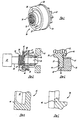
- FIG. 1 shows a drive arrangement 20 for driving a pinion 22.
- the pinion has a disc base 24.
- a rubber cushion 26 is received between the pinion 22 and a drive plate 28.
- the drive plate 28 is has a tubular portion 30 which includes a thread which is formed on a double helix 32.
- a flange 27 extends radially from the tubular portion 30.
- a drive shaft 34 (shown in phantom) is mounted to a motor 35.
- the motor 35 drives the drive shaft.
- a thread 36 on the outer periphery of the drive shaft 34 moves within the threads 32.
- An unthreaded portion 38 of the drive shaft extends through the pinion 22.
- a snap ring 40, or other structure, locks the rubber cushion 26 and drive plate 28 onto the drive shaft 34.
- a ring gear 42 is positioned adjacent the pinion 22.
- the pinion 22 engages teeth on an inner periphery of the ring gear 42.
- the ring gear 42 is associated with an internal combustion engine of the vehicle, and will start to turn the internal combustion engine.
- the rotation of pinion 22 is initially stopped due to the high torque required to drive the ring gear and its associated internal combustion engine.
- the drive plate 28 continues to move on threads 36, and it moves to the right as shown in FIG. 2. As the drive plate 28 moves, it compresses the rubber cushion 26. Once the rubber cushion has been compressed a sufficient amount, the drive plate begins to also transmit torque to the pinion 22. At that time, there is sufficient torque to turn the ring gear 42.
- FIG. 3 shows the connection of the rubber cushion 26 and drive plate 28.
- the rubber cushion 26 includes an outer seal lip 44 defined around a channel 45 that receives the flange 27 of the drive plate 28.
- An inner lip 46 is formed on an inner periphery and abuts an inner neck 47 of the drive plate.
- the inner neck 47 has an outer diameter which is greater than an inner diameter of the lip 46.
- the outer lip 44 is deformed by the flange 27 when received in the channel 45.
- the lip 44 thus provides a seal at the outer periphery. An area 50 between the lips 44 and 46 is thus sealed.
- FIG. 4 shows a relaxed view of the outer lip 44 and the channel 45.
- the outer lip 44 has a cross-sectional shape in its relaxed position which is somewhat different than the shape shown in FIG. 3 when the lip 44 is deformed by the flange 27.
- FIG. 5 shows the inner lip 46 in the relaxed position.
Landscapes
- Engineering & Computer Science (AREA)
- Chemical & Material Sciences (AREA)
- Combustion & Propulsion (AREA)
- Mechanical Engineering (AREA)
- General Engineering & Computer Science (AREA)
- Connection Of Motors, Electrical Generators, Mechanical Devices, And The Like (AREA)
- Sealing With Elastic Sealing Lips (AREA)
Claims (6)
- Assemblage d'entraínement pour un moteur de démarrage (35), comprenant:caractérisé en ce que ledit coussin amortisseur (26) comporte un canal (45) recevant la bride (27) de ladite plaque d'entraínement (28), ledit coussin amortisseur (26) comportant un rebord radialement interne (46) déformé par ladite plaque d'entraínement (28) et établissant l'étanchéité sur celle-ci au niveau d'un col interne (47) espacé vers ledit pignon (22) à partir de ladite bride (27), et un rebord radialement externe (44) déformé au-dessus de ladite plaque d'entraínement (28) et établissant l'étanchéité sur celle-ci au niveau d'une position espacée radialement vers l'extérieur dudit rebord interne (46).un moteur électrique (35) comportant un arbre d'entraínement (34), ledit arbre d'entraínement comportant un filetage (36) sur au moins une partie de sa longueur axiale;une plaque d'entraínement (28) comportant un filetage interne (32) reçu sur ladite partie dudit arbre d'entraínement (34) et comportant une bride à extension radiale (27);un pignon (22) devant être entraíné par ledit arbre d'entraínement (34), ledit pignon (22) comportant des dents d'engrenage destinées à s'engager sélectivement dans une partie d'un démarreur de moteur, ladite plaque d'entraínement (28) étant positionnée plus près dudit moteur (35) que ledit pignon (22); etun coussin amortisseur (26) positionné entre ladite plaque d'entraínement (28) et ledit pignon (22),
- Assemblage d'entraínement selon la revendication 1, caractérisé en ce que ledit rebord interne (46) s'étend radialement vers l'intérieur vers un diamètre intérieur, ledit col interne (47) de ladite plaque d'entraínement (28) ayant un diamètre extérieur supérieur audit diamètre intérieur, de sorte que ledit col interne (47) déforme ledit rebord interne (46).
- Assemblage d'entraínement selon les revendications 1 ou 2, dans lequel ledit rebord externe (44) établit l'étanchéité par rapport à une face externe de ladite bride (47) sur un côté de ladite bride (47) opposé audit rebord interne (46).
- Assemblage d'entraínement selon les revendications 1, 2 ou 3, dans lequel ledit rebord externe (44) est espacé en direction axiale vers ledit moteur (35), par rapport audit rebord interne (46).
- Assemblage d'entraínement selon l'une quelconque des revendications précédentes, dans lequel ladite plaque d'entraínement (28) comporte des filetages (32) au niveau d'une surface périphérique interne, ledit arbre (34) comportant des filetages (36) sur une surface périphérique externe, ladite plaque d'entraínement (28) étant du type se déplaçant sur lesdits filetages pour comprimer ledit coussin amortisseur (26) et accroítre le couple appliqué par ledit arbre (34) audit pignon (22).
- Assemblage d'entraínement selon l'une quelconque des revendications précédentes, dans lequel ledit coussin amortisseur (26) est composé de caoutchouc.
Applications Claiming Priority (2)
| Application Number | Priority Date | Filing Date | Title |
|---|---|---|---|
| US248959 | 1999-02-12 | ||
| US09/248,959 US5998895A (en) | 1999-02-12 | 1999-02-12 | Seal for starter motor drive |
Publications (2)
| Publication Number | Publication Date |
|---|---|
| EP1028251A1 EP1028251A1 (fr) | 2000-08-16 |
| EP1028251B1 true EP1028251B1 (fr) | 2004-12-08 |
Family
ID=22941442
Family Applications (1)
| Application Number | Title | Priority Date | Filing Date |
|---|---|---|---|
| EP00300955A Expired - Lifetime EP1028251B1 (fr) | 1999-02-12 | 2000-02-08 | Etanchéité pour pinion de démarreur |
Country Status (7)
| Country | Link |
|---|---|
| US (1) | US5998895A (fr) |
| EP (1) | EP1028251B1 (fr) |
| JP (1) | JP2000234580A (fr) |
| CN (1) | CN1114039C (fr) |
| BR (1) | BR0000370A (fr) |
| DE (1) | DE60016476T2 (fr) |
| ES (1) | ES2230029T3 (fr) |
Families Citing this family (5)
| Publication number | Priority date | Publication date | Assignee | Title |
|---|---|---|---|---|
| US20060117876A1 (en) * | 2004-12-07 | 2006-06-08 | Remy International, Inc. | Sealed and oil lubricated starter motor gear reduction and overrunning clutch mechanism |
| JP2008163818A (ja) * | 2006-12-28 | 2008-07-17 | Hitachi Ltd | スタータ |
| JP4831035B2 (ja) * | 2007-09-26 | 2011-12-07 | 株式会社デンソー | スタータ |
| FR2963392B1 (fr) * | 2010-07-27 | 2016-03-04 | Valeo Equip Electr Moteur | Demarreur a lanceur equipe d'un systeme d'accouplement pour accoupler un pignon monte fou a son arbre rotor et son procede |
| CN102345546A (zh) * | 2010-08-02 | 2012-02-08 | 德昌电机(深圳)有限公司 | 启动器 |
Family Cites Families (13)
| Publication number | Priority date | Publication date | Assignee | Title |
|---|---|---|---|---|
| US2455328A (en) * | 1947-09-02 | 1948-11-30 | Bendix Aviat Corp | Engine starter gearing and control |
| US2818735A (en) * | 1956-02-23 | 1958-01-07 | Bendix Aviat Corp | Starter gearing for internal combustion engines |
| DE1957233A1 (de) * | 1969-11-14 | 1971-05-19 | Bosch Gmbh Robert | Schraubtrieb fuer Andrehmotoren von Brennkraftmaschinen |
| US3791684A (en) * | 1972-08-24 | 1974-02-12 | Eaton Stamping Co | Electric starter motor |
| US3791685A (en) * | 1972-08-24 | 1974-02-12 | Eaton Stamping Co | Starter pinion with molded base and drive |
| US4308462A (en) * | 1980-01-17 | 1981-12-29 | Ambac Industries, Incorporated | Engine starter system with improved structure for maintaining engine engagement |
| US4330713A (en) * | 1980-04-16 | 1982-05-18 | Eaton Stamping Company | Cushioned starter pinion |
| US4347442A (en) * | 1980-07-14 | 1982-08-31 | Eaton Stamping Company | Double insulated starter motor |
| US4369666A (en) * | 1980-11-19 | 1983-01-25 | Eltra Corporation | Starter drive assembly |
| US4479394A (en) * | 1981-06-18 | 1984-10-30 | Eaton Stamping Company | Electric starter with confined cushion |
| US5046373A (en) * | 1989-08-07 | 1991-09-10 | Briggs & Stratton Corp. | Starter motor construction |
| JPH0532771U (ja) * | 1991-10-08 | 1993-04-30 | 株式会社三ツ葉電機製作所 | スタータ |
| US5241871A (en) * | 1992-10-23 | 1993-09-07 | United Technologies Motor Systems, Inc. | Torque limiting starter drive clutch assembly |
-
1999
- 1999-02-12 US US09/248,959 patent/US5998895A/en not_active Expired - Fee Related
-
2000
- 2000-02-08 JP JP2000030562A patent/JP2000234580A/ja active Pending
- 2000-02-08 DE DE60016476T patent/DE60016476T2/de not_active Expired - Fee Related
- 2000-02-08 ES ES00300955T patent/ES2230029T3/es not_active Expired - Lifetime
- 2000-02-08 EP EP00300955A patent/EP1028251B1/fr not_active Expired - Lifetime
- 2000-02-11 BR BR0000370-0A patent/BR0000370A/pt not_active IP Right Cessation
- 2000-02-12 CN CN00104864A patent/CN1114039C/zh not_active Expired - Fee Related
Also Published As
| Publication number | Publication date |
|---|---|
| EP1028251A1 (fr) | 2000-08-16 |
| CN1114039C (zh) | 2003-07-09 |
| DE60016476D1 (de) | 2005-01-13 |
| CN1264797A (zh) | 2000-08-30 |
| US5998895A (en) | 1999-12-07 |
| DE60016476T2 (de) | 2005-12-15 |
| BR0000370A (pt) | 2000-09-12 |
| ES2230029T3 (es) | 2005-05-01 |
| JP2000234580A (ja) | 2000-08-29 |
Similar Documents
| Publication | Publication Date | Title |
|---|---|---|
| KR910002120B1 (ko) | 유성 기어식 감속 시동기 | |
| US20020096885A1 (en) | Pinion assembly | |
| US20090052821A1 (en) | Method of supporting a shaft on bearings and bearing arrangement | |
| EP1028251B1 (fr) | Etanchéité pour pinion de démarreur | |
| CA2018687C (fr) | Joint etanche a l'humidite pour pignon a translation dans un demarreur | |
| US3789690A (en) | Overload release device for a motor drive | |
| US5688203A (en) | Planetary gear reduction starter | |
| US4479394A (en) | Electric starter with confined cushion | |
| RU2386851C1 (ru) | Стартер для двигателя внутреннего сгорания | |
| MXPA00001401A (en) | Seal for starter motor drive | |
| US2935860A (en) | Torque-converter seal | |
| CN1048540C (zh) | 带中间齿轮的起动电动机 | |
| US20080312018A1 (en) | Power transmission and hub used for power transmission | |
| CN1079136C (zh) | 具有啮合器齿轮的汽车起动机及这种啮合器的安装方法 | |
| CN1076441C (zh) | 具有改进的密封件的汽车发动机起动机 | |
| KR100211698B1 (ko) | 차동 장치와 드라이브 축 연결 구조 | |
| EP3875749B1 (fr) | Appareil de démarrage pour entrainer un moteur à combustion interne et système de démarreur pour un moteur à combustion interne | |
| CN221009910U (zh) | 一种防水直线电机 | |
| CN219543217U (zh) | 电动夹持执行器 | |
| AU2967795A (en) | Engine starter gearing having improved grease retention | |
| JPS6313426Y2 (fr) | ||
| JP3549237B2 (ja) | 一方向クラッチのシール機構 | |
| JPS6139128Y2 (fr) | ||
| KR19980020690U (ko) | 시동모우터의 오버러닝클러치 어셈블리 | |
| CN116529506A (zh) | 滚珠丝杠装置 |
Legal Events
| Date | Code | Title | Description |
|---|---|---|---|
| PUAI | Public reference made under article 153(3) epc to a published international application that has entered the european phase |
Free format text: ORIGINAL CODE: 0009012 |
|
| AK | Designated contracting states |
Kind code of ref document: A1 Designated state(s): DE ES FR GB IT |
|
| AX | Request for extension of the european patent |
Free format text: AL;LT;LV;MK;RO;SI |
|
| RIN1 | Information on inventor provided before grant (corrected) |
Inventor name: RODRIGUEZ, EDUARDO Inventor name: THRASHER JR.,ROBERT, C/O JOHNSON EL.AUT.MOTORS INC |
|
| 17P | Request for examination filed |
Effective date: 20010111 |
|
| AKX | Designation fees paid |
Free format text: DE ES FR GB IT |
|
| 17Q | First examination report despatched |
Effective date: 20030718 |
|
| GRAP | Despatch of communication of intention to grant a patent |
Free format text: ORIGINAL CODE: EPIDOSNIGR1 |
|
| GRAS | Grant fee paid |
Free format text: ORIGINAL CODE: EPIDOSNIGR3 |
|
| GRAA | (expected) grant |
Free format text: ORIGINAL CODE: 0009210 |
|
| AK | Designated contracting states |
Kind code of ref document: B1 Designated state(s): DE ES FR GB IT |
|
| REG | Reference to a national code |
Ref country code: GB Ref legal event code: FG4D |
|
| REF | Corresponds to: |
Ref document number: 60016476 Country of ref document: DE Date of ref document: 20050113 Kind code of ref document: P |
|
| REG | Reference to a national code |
Ref country code: ES Ref legal event code: FG2A Ref document number: 2230029 Country of ref document: ES Kind code of ref document: T3 |
|
| PLBE | No opposition filed within time limit |
Free format text: ORIGINAL CODE: 0009261 |
|
| STAA | Information on the status of an ep patent application or granted ep patent |
Free format text: STATUS: NO OPPOSITION FILED WITHIN TIME LIMIT |
|
| 26N | No opposition filed |
Effective date: 20050909 |
|
| ET | Fr: translation filed | ||
| PGFP | Annual fee paid to national office [announced via postgrant information from national office to epo] |
Ref country code: ES Payment date: 20090317 Year of fee payment: 10 |
|
| PGFP | Annual fee paid to national office [announced via postgrant information from national office to epo] |
Ref country code: DE Payment date: 20090206 Year of fee payment: 10 |
|
| PGFP | Annual fee paid to national office [announced via postgrant information from national office to epo] |
Ref country code: GB Payment date: 20090204 Year of fee payment: 10 |
|
| PGFP | Annual fee paid to national office [announced via postgrant information from national office to epo] |
Ref country code: IT Payment date: 20090213 Year of fee payment: 10 |
|
| PGFP | Annual fee paid to national office [announced via postgrant information from national office to epo] |
Ref country code: FR Payment date: 20090213 Year of fee payment: 10 |
|
| GBPC | Gb: european patent ceased through non-payment of renewal fee |
Effective date: 20100208 |
|
| REG | Reference to a national code |
Ref country code: FR Ref legal event code: ST Effective date: 20101029 |
|
| PG25 | Lapsed in a contracting state [announced via postgrant information from national office to epo] |
Ref country code: FR Free format text: LAPSE BECAUSE OF NON-PAYMENT OF DUE FEES Effective date: 20100301 |
|
| PG25 | Lapsed in a contracting state [announced via postgrant information from national office to epo] |
Ref country code: DE Free format text: LAPSE BECAUSE OF NON-PAYMENT OF DUE FEES Effective date: 20100901 |
|
| REG | Reference to a national code |
Ref country code: ES Ref legal event code: FD2A Effective date: 20110310 |
|
| PG25 | Lapsed in a contracting state [announced via postgrant information from national office to epo] |
Ref country code: IT Free format text: LAPSE BECAUSE OF NON-PAYMENT OF DUE FEES Effective date: 20100208 Ref country code: GB Free format text: LAPSE BECAUSE OF NON-PAYMENT OF DUE FEES Effective date: 20100208 |
|
| PG25 | Lapsed in a contracting state [announced via postgrant information from national office to epo] |
Ref country code: ES Free format text: LAPSE BECAUSE OF NON-PAYMENT OF DUE FEES Effective date: 20110309 |
|
| PG25 | Lapsed in a contracting state [announced via postgrant information from national office to epo] |
Ref country code: ES Free format text: LAPSE BECAUSE OF NON-PAYMENT OF DUE FEES Effective date: 20100209 |