BACKGROUND OF THE INVENTION
Field of the Invention
-
The present invention relates to a color stencil
printer, and more particularly to an improvement in printing
quality resulting from a difference in the dot gain of ink,
particularly a variation in hue.
Description of the Related Art
-
A printer, such as a thermal printer, a copying machine,
a stencil printer and the like are known as an image forming
apparatus which outputs the same image as a read image to printing
paper or the like, based on an original image signal read by
a reading section having a charge-coupled device (CCD) line
sensor or the like.
-
In the above-mentioned stencil printer, a stencil
making section, consisting of a thermal head and a platen roller,
perforates a stencil paper, based on an original image signal
read by the reading section. Then, the perforated stencil paper
is wound around a printing drum. Next, printing paper is
inserted between the printing drum and a press roller which
rotates in contact with the printing drum. Ink inside the
printing drum is pushed out to the printing paper through the
perforations in the perforated stencil paper, whereby ink
transfer is performed. In this way, printing is performed.
-
With recent advances in image coloring, color stencil
printers have been proposed which make a perforated stencil paper
using a thermal head for each color to be used in printing and
perform color printing by performing overprinting, using the
perforated stencil paper for each color.
-
When color printing is performed with the color
stencil printer, enhancing image gradation or printing in a
desired tone of color is very important in order to enhance the
quality of a printed image. For that purpose, gradation and
color-tone controls are indispensable. To perform these
controls, scanner γ-correction, color-tone control, printer γ
-correction, gradation control and the like have hitherto been
performed.
-
As a method of embodying gradation control in this
color processing, a method of controlling printing for each color
by various kinds of image processing, such as half tone
processing (such as a dithering method and an error diffusing
method) and the like, is common. Also, as a method of embodying
color-tone control, it is common to convert a read color image
to an arbitrary color space and then adjust the image so that
it has a desired tone of color on the color space.
-
In such methods of embodying gradation control and
color-tone control, control is performed on the assumption that
the dot gains of inks to be used in printing are all the same.
The "dot gain" used herein means a ratio of the size of ink,
transferred onto a printing paper through a perforation formed
in a stencil paper, to the size of the perforation.
-
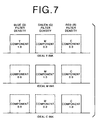
The control is also performed on the assumption that
ink to be used is ideal ink in which the spectral density, as
shown in Figure 7, includes only the spectral component of a
necessary color for each color and does not include an
unnecessary spectral component. Furthermore, the control is
performed on the assumption that, if inks differ in ink type
but are the same in color, the spectral densities are also the
same.
-
However, the dot gains of inks that are actually used
are not always the same. If inks differ in color, the dot gains
thereof will differ, and even if inks are the same in color but
if inks differ in ink type, the dot gains will differ. For this
reason, if printing is performed with inks differing in dot gain
by a single thermal head, there is a problem that desired printing
quality will not be obtained, even if the above-mentioned
gradation or color-tone control were performed. For instance,
a magenta color becomes lighter as a whole than a cyan color.
If overprinting is performed, a bluish image will be obtained,
or it will be reversed. Thus, a desired tone of color cannot
be brought out.
-
As primary factors having influence on the dot gain
of ink, the following are considered. What is expressed to be
greater by a sign of inequality is that the dot gain of ink is
greater.
(1) Ink, a master fiber, and paper
-
- Ink viscosity: soft > hard
- Master fiber: Japanese paper > chemical fiber
- Surface roughness of paper: RISO paper > fine paper
(RISO SR paper) > simple coated paper (inkjet paper) >
rough dyed paper (smoother than inkjet paper) >
perfect coated paper
-
-
The "RISO paper" and "RISO SR paper" here means
printing paper made by RISO KAGAKU Corporation.
(2) Control information
-
- Platen pressure: strong > weak
- Pressure-applying time: long > short
- Printing speed: slow > fast
-
(3) Others
-
- Temperature: high > low
-
-
In addition, the spectral density of each ink to be
actually used includes not only the spectral component of a
necessary color but also unnecessary spectral absorption called
auxiliary absorption. For example, yellow ink absorbs not only
a Blue component but also components other than the Blue
component. Therefore, each ink that is actually used has
spectral density such as that shown in Figure 8. For that reason,
in mixing colors, the inks will become too deep because a certain
spectral density is polarized. Therefore, even if the dot gains
of all inks are the same, a problem that desired printing quality
(tone of color) will not be obtained will arise. Furthermore,
there are cases where even if inks are the same color, the
spectral densities will differ if the inks differ in ink type.
For that reason, even if perforation sizes are the same, a problem
will arise that the spectral densities of inks will differ if
the inks differ in ink type.
SUMMARY OF THE INVENTION
-
In view of the foregoing observations and description,
the primary object of the present invention is to provide a color
stencil printer which is capable of obtaining desired printing
quality even when the dot gains of inks to be used in printing
differ or even when the spectral densities of the inks are not
ideal.
-
To achieve the above object and in accordance with the
present invention, there is provided a color stencil printer
comprising
- stencil making means which perforates a heat-sensitive
stencil paper using a thermal head, based on input
binary image data, and
- printing means which performs printing by
transferring ink to printing paper through a perforation of the
perforated stencil paper,
wherein the stencil making means includes - dot-gain information input means which inputs dot-gain
information representative of a dot gain of ink for each
ink type to be used in the printing and/or spectral-density
information input means which inputs spectral-density
information representative of the spectral density of the ink,
and
- perforation-size control means which controls the
size of the perforation, based on the dot-gain information and/or
the spectral-density information.
-
-
In a preferred form of the present invention, the
perforation-size control means performs gradation control
and/or color-tone control by controlling the size of the
perforation.
-
In the color stencil printer according to the present
invention, the binary image data may be data on which half tone
processing has been performed.
-
According to the stencil printer of the present
invention, the size of the perforation is controlled for each
ink type to be used in printing, based on the dot gain and spectral
density of the ink. Therefore, even if the dot gains of inks
differ, or even if the spectral densities of the inks are not
ideal, the perforation can be formed into a suitable printing
dot size in consideration of the dot gain and spectral density
of ink to be actually used.
-
In addition, the perforation size is controlled to
control printing dot size. By controlling this perforation size,
it becomes possible to perform gradation control and/or
color-tone control. Although the color processing in the
conventional stencil printer requires image processing such as
scanner γ-correction, color-tone control, printer γ-correction,
gradation processing and the like, the stencil
printer of the present invention renders simple and free color
adjustments possible. Furthermore, since the perforation size
is controlled for each ink type in consideration of the dot gain
and spectral density of the ink, printing can always be performed
in a predetermined printing dot size, even if inks differ in
ink type.
BRIEF DESCRIPTION OF THE DRAWINGS
-
- Figure 1 is a block diagram showing the stencil making
section of a color stencil printer constructed according to the
present invention,
- Figure 2 is a block diagram showing the head drive
means of the stencil making section shown in Figure 1,
- Figure 3 is a block diagram showing another example
of the stencil making section shown in Figure 1,
- Figure 4 is a diagram showing pattern examples for a
heating signal,
- Figure 5 is a diagram showing an example of density
expression corresponding to the pattern of the heating signal,
- Figure 6 is a diagram showing variations in the color
tone of a printed color corresponding to the density expression,
- Figure 7 is a diagram showing the spectral density of
ideal ink, and
- Figure 8 is a diagram showing the spectral density of
actual ink.
-
DESCRIPTION OF THE PREFERRED EMBODIMENTS
-
A preferred embodiment of a color stencil printer
according to the present invention will hereinafter be described
in detail with reference to the drawings.
-
As shown in Figure 1, the stencil making section of
the color stencil printer comprises (1) head drive means 70 which
drives each heating element 90 constituting a thermal head, based
on input binary image data D0, (2) dot-gain information input
means 80 which inputs dot-gain information representative of
the dot gain of ink for each ink type to be used in printing,
(3) spectral-density information input means 82 which inputs
spectral-density information representative of the spectral
density of the ink, and (4) perforation-size control means 84
which is connected to the head drive means 70 and controls the
size of a perforation formed in a stencil paper 23 inserted
between the thermal head and a platen roller 33, based on the
input dot-gain information and spectral-density information.
-
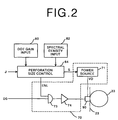
Figure 2 shows the construction of the head drive means
70 in greater detail. As shown in the figure, the
perforation-size control means 84 outputs a heating signal ENL
and a voltage control signal S to the head drive means 70. The
heating signal ENL prescribes a heating time for the heating
element 90, while the voltage control signal S controls the
output voltage VD of a power source 71.
-
The head drive means 70 comprises the power source 71
for the heating element 90 constituting the thermal head, an
AND gate 73 which performs the logic AND operation between the
input binary image D0 and heating signal ENL, and a buffer 74
which transmits this gate output to the thermal head. The binary
image data D0 is input as serial data and converted to parallel
data by shift registers (not shown). The parallel data is input
to the AND gate 73. With the logic AND operation between the
binary image D0 and the heating signal ENL which is issued at
desired timing, each heating element 90 constituting the thermal
head is turned on and heated at the desired timing. In performing
one perforation for one pixel, a predetermined voltage VD is
continuously applied from the power source 71 to each heating
element 90 over a fixed time, based on the heating signal ENL.
Therefore, the size of the perforation which is formed in the
stencil paper 23 varies according to the applied voltage VD and
the heating time. Information J representative of the type of
binary image data D0, such as information indicating normal data,
information indicating half tone processing has been performed
on the data, information indicating what kind of half tone
processing has been performed on the data, is input to the
perforation-size control means 84. The perforation-size
control means 84 controls the applied voltage VD and the heating
time so that a perforation is formed into a predetermined size
corresponding to the type of the binary image data D0.
-
Now, the operation of the stencil printer with the
aforementioned construction will be described.
-
The dot-gain information representative of the dot
gain of ink is input for each ink type to be used in printing
by the dot-gain information input means 80. Similarly, the
spectral-density information representative of the spectral
density of the ink is input by the spectral-density information
input means 82. The input dot-gain information and
spectral-density information are temporarily stored in memory
(not shown). Note that when there are a plurality of ink types,
it is preferable that the information be stored for each ink
type.
-
The inks used in printing have three colors, yellow
(Y), cyan (C), and magenta (M), respectively. Also, assume that
the spectral densities of the three color inks are ideal as shown
in Figure 7.
-
Since the stencil paper 23 is formed for each color,
the binary image data D0 is also input for each color. For
example, data is extracted for each color by a scanner (not shown),
whereby image data is generated for each color.
-
Based on the information J representative of the type
of the input image data D0, the perforation-size control means
84 outputs the heating signal ENL corresponding to the dot gain
of each ink and the voltage control signal S so that the printing
dot size of each ink becomes a printing dot size corresponding
to the information J. In forming a perforation in the stencil
paper 23, the perforation-size control means 84 drives the
heating element 90 in accordance with the heating time and the
applied voltage VD, taking the dot gain of each ink into
consideration so that the printing dot size of the ink becomes
a printing dot size corresponding to the information J.
-
Unless the dot gain of ink is taken into consideration,
hue degradation will occur due to a variation in the dot gain
and auxiliary absorption. However, in the stencil printer
according to the present invention, control is performed so that
printing dot size becomes a predetermined size. Therefore, hue
degradation is improved. Note that while it has been described
that the heating time and the applied voltage VD are both set
in consideration of the dot gain or spectral density, either
only one or the other of the two may be set in consideration
of the dot gain or spectral density.
-
It has also been described that in consideration of
the dot gain of ink, the perforation size is controlled so that
printing dot size becomes a predetermined size. However, when
the spectral density of each ink to be used in printing is not
an ideal one shown in Figure 7, the perforation size may be
controlled, in consideration of the spectral density of ink input
by the spectral-density information input means 82, so that the
hue of printed matter becomes a desired one.
-
In addition, in the stencil printer according to the
present invention, in consideration of the dot gain or spectral
density of ink for each ink type, the heating time and the applied
voltage VD are controlled in order to control the perforation
size, and in addition to this, it is possible to control the
perforation size so that it becomes a printing dot size
corresponding to gradation control or color-tone control. A
description will hereinafter be given with regard to the case
of performing gradation control or color-tone control.
-
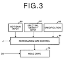
Figure 3 shows the stencil making section of a stencil
printer which performs gradation control or color-tone control.
As shown in the figure, specification means 86 for specifying
gradation or a color tone is connected to perforation-size
control means 84.
-
Figure 4 shows pattern examples for the heating signal
ENL which controls the heating time (i.e., the time during which
voltage is applied to the heating element 90a) in performing
gradation control or color-tone control. In Figure 4 there are
shown 4 patterns, "no applying time", "short applying time",
"intermediate applying time", and "long applying time". The
perforation-size control means 84 selects one of these patterns
for each color in accordance with gradation or a color tone
specified by the specification means 86 and controls the size
of a perforation.
-
Figure 5 shows 4-level density expression
corresponding to the 4 patterns of the heating signal ENL shown
in Figure 4. "None" in the density expression corresponds to
the "no applying time" of the 4 patterns, "light" to the "short
applying time", "average" to the "intermediate applying time",
and "deep" to the "long applying time". Note that this density
expression may be set arbitrarily.
-
For cyan, magenta, and yellow which are actually
printed, variations in the hue of each printed color
corresponding to the above-mentioned density expression are
shown in Figure 6. For instance, if cyan is set to "none", a
reddish hue is obtained as a whole, and if it is set to "deep",
a light bluish hue is obtained as a whole. Also, if magenta is
set to "none", a greenish hue occurs as a whole, and if it is
set to "deep", a purplish hue occurs as a whole. Likewise, yellow
set to "none" results in a bluish hue, and if set to "deep",
a yellowish hue occurs as a whole. If cyan, magenta, and yellow
are further combined with one another, it becomes possible to
obtain various hues freely and therefore color-tone control
becomes possible. The conventional color processing requires
image processing such as scanner γ-correction, color correction,
printer γ-correction, gradation processing and the like,
whereas the stencil printer of the present invention is able
to make simple and free color adjustments, because the color-tone
control is performed by controlling the size of a perforation
and, as described above, phased-color expression can be used
in performing color-tone control. In addition, in performing
this color-tone control, the perforation size is controlled for
each ink type in consideration of the dot gain or spectral density
of ink. Therefore, printing can always be performed in a
predetermined printing dot size without regard to ink types,
and consequently, a desired color tone can be obtained at all
times.
-
While it has been described that in the above-mentioned
color-tone control, the size of a perforation , i.e.,
printing dot size is controlled by controlling the heating time,
the present invention is not limited to this control, but it
is a matter of course that printing dot size may be controlled
by controlling voltage VD which is applied to the heating
element.
-
Furthermore, although the color-tone control has been
described, it is a matter of course that the present invention
is also applicable to mono-tone gradation control in the same
manner. It is also a matter of course that half tone control
can be performed by taking advantage of this gradation control.
-
In the stencil printer according to the present
invention, binary image data that is input may be data on which
half tone processing has been performed. As shown in Figure 2,
information J representative of the type of the binary image
data D0 is input to the perforation-size control means 84, and
the perforation-size control means 84, as with the control signal
generation means in the conventional stencil printer, controls
the applied voltage VD and the heating time so that a perforation
is formed into a predetermined size corresponding to the type
of half tone processing such as an error diffusing method and
a dithering method. In performing this control, for example,
if the heating time and the applied voltage VD are controlled
for each ink type in consideration of the dot gain or spectral
density of ink, as described above, the perforating size can
be controlled so that it becomes a desired printing dot size.