EP1027752B1 - Elektrisches gerät - Google Patents
Elektrisches gerät Download PDFInfo
- Publication number
- EP1027752B1 EP1027752B1 EP98949152A EP98949152A EP1027752B1 EP 1027752 B1 EP1027752 B1 EP 1027752B1 EP 98949152 A EP98949152 A EP 98949152A EP 98949152 A EP98949152 A EP 98949152A EP 1027752 B1 EP1027752 B1 EP 1027752B1
- Authority
- EP
- European Patent Office
- Prior art keywords
- region
- fabricated
- magnetising
- assemblies
- magnetic field
- Prior art date
- Legal status (The legal status is an assumption and is not a legal conclusion. Google has not performed a legal analysis and makes no representation as to the accuracy of the status listed.)
- Expired - Lifetime
Links
- 230000005291 magnetic effect Effects 0.000 claims description 87
- 239000000463 material Substances 0.000 claims description 61
- 229910000859 α-Fe Inorganic materials 0.000 claims description 24
- 230000035699 permeability Effects 0.000 claims description 19
- 210000000746 body region Anatomy 0.000 claims description 15
- 230000000712 assembly Effects 0.000 claims description 14
- 238000000429 assembly Methods 0.000 claims description 14
- 239000000203 mixture Substances 0.000 claims description 6
- 230000005855 radiation Effects 0.000 claims description 5
- 230000001747 exhibiting effect Effects 0.000 claims description 2
- 239000002184 metal Substances 0.000 claims description 2
- 229910052751 metal Inorganic materials 0.000 claims description 2
- 230000004907 flux Effects 0.000 description 17
- 230000000694 effects Effects 0.000 description 7
- 230000010363 phase shift Effects 0.000 description 5
- 238000010276 construction Methods 0.000 description 4
- 230000001276 controlling effect Effects 0.000 description 4
- 230000008901 benefit Effects 0.000 description 3
- 239000003989 dielectric material Substances 0.000 description 3
- 238000004519 manufacturing process Methods 0.000 description 3
- 230000001902 propagating effect Effects 0.000 description 3
- XEEYBQQBJWHFJM-UHFFFAOYSA-N Iron Chemical compound [Fe] XEEYBQQBJWHFJM-UHFFFAOYSA-N 0.000 description 2
- 230000005540 biological transmission Effects 0.000 description 2
- 230000000875 corresponding effect Effects 0.000 description 2
- 230000001419 dependent effect Effects 0.000 description 2
- 238000001228 spectrum Methods 0.000 description 2
- 229910001209 Low-carbon steel Inorganic materials 0.000 description 1
- 230000004888 barrier function Effects 0.000 description 1
- 230000009286 beneficial effect Effects 0.000 description 1
- 238000000576 coating method Methods 0.000 description 1
- 239000012141 concentrate Substances 0.000 description 1
- 230000005670 electromagnetic radiation Effects 0.000 description 1
- 238000003384 imaging method Methods 0.000 description 1
- 238000003780 insertion Methods 0.000 description 1
- 230000037431 insertion Effects 0.000 description 1
- 230000003993 interaction Effects 0.000 description 1
- 229910052742 iron Inorganic materials 0.000 description 1
- 230000007246 mechanism Effects 0.000 description 1
- 230000000149 penetrating effect Effects 0.000 description 1
Images

Classifications
-
- H—ELECTRICITY
- H01—ELECTRIC ELEMENTS
- H01Q—ANTENNAS, i.e. RADIO AERIALS
- H01Q3/00—Arrangements for changing or varying the orientation or the shape of the directional pattern of the waves radiated from an antenna or antenna system
- H01Q3/44—Arrangements for changing or varying the orientation or the shape of the directional pattern of the waves radiated from an antenna or antenna system varying the electric or magnetic characteristics of reflecting, refracting, or diffracting devices associated with the radiating element
Definitions
- This invention relates to a device which is adapted to be positioned in the path of a beam of electromagnetic radiation propagating in free space which changes characteristics of the beam.
- the invention is particularly, but not exclusively, concerned with microwave devices.
- microwave refers to the part of the electromagnetic spectrum substantially in the frequency range 0.2 to 300GHz. It includes that part of the spectrum referred to as millimetre wave (having a frequency in the range 30 to 300GHz).
- the microwave beam passes through a rectangular block of dielectric material formed by two wedge-shaped pieces, one being of ferrite material and one being of non-ferrite material, the pieces having their sloping faces in juxtaposition.
- An external magnetic field is applied to the block in a direction perpendicular to the direction of propagation of the microwave beam.
- the magnetic field is substantially constant across the block.
- Applied magnetic field induces magnetisation in the material which is substantially uniform across the block.
- a microwave beam passing through the magnetised material will interact with it and this interaction changes relative velocity across the beam. If a microwave beam is directed through the block so as to travel in turn through a thickness of the ferrite and then through a thickness of the non-ferrite material, certain parts of the beam will travel through a different length of ferrite material compared to certain other parts of the beam thus causing a differential phase shift across the block.
- the phase at one edge will lag when compared to the phase at the other edge and the beam will be deflected. Altering the direction of the magnetic field will cause the beam to deflect in an opposite direction.
- the beam passes through a cylinder of material formed by two wedge-shaped pieces, one being of ferrite and one being of non-ferrite material, the pieces having the sloping faces in juxtaposition.
- the cylinder is located within an external solenoid which is used to apply a magnetic field along the longitudinal axis of the cylinder which is substantially parallel to the direction of propagation of the beam.
- the magnetic field is substantially constant across the cylinder.
- the device operates by Faraday rotation. For circularly polarised beams such a device induces a differential phase shift in the beam thus causing deflection of the beam.
- Linearly polarised beams are equivalent to a combination of two circularly polarised beams rotating in opposite directions and so such a device splits a linearly polarised beam into two separate circularly polarised beams leaving the device at angles + ⁇ ° and - ⁇ ° to the direction of propagation of the original beam.
- Devices of this kind are difficult to construct and cause in-line loss due to beam reflection at the junction between the ferrite and non-ferrite wedge shaped pieces. Such devices provide beam deflection in one plane only and so two devices in series would be required to produce conical steering.
- Another device for controlling the direction of a microwave beam comprises a body of ferrite material having magnetic coils which apply a magnetic field across the body which induces a gradient in magnetisation across the body.
- the resultant direction of the beam leaving the device is perpendicular to the gradient in the magnetic field across the body. Therefore, the degree of deflection in the beam is controlled by the gradient in the magnetisation.
- the device differs from the two devices described above in that all parts across the width of a microwave beam pass through the same thickness of ferrite material. However, magnetisation induced varies across the ferrite material through which the microwave beam passes.
- a disadvantage with this device is that the thickness of the body is governed by its width. If the body is relatively thin compared to its width, magnetic flux tends to concentrate around the coils and so does not penetrate sufficiently across the width of an aperture through which the beam passes and little or no magnetic flux passes through the body in a central region of the aperture.
- the width of the material is governed by the width of the beam which the device is to steer and so cannot be chosen independently. As a result, devices of this type need to have a thickness and a width which are comparable. This causes the devices to be bulky, heavy, cumbersome and expensive. Furthermore, a thicker material causes greater insertion loss in a system.
- the invention provides a device for receiving a first beam of microwave radiation and controlling the direction of a corresponding second beam of microwave radiation output from the device, the second beam being derived from the first beam, the device including:
- the invention provides the advantage that use of the spatially non-uniform magnetic reluctance for directing a relatively greater proportion of the magnetic field to penetrate through the central region ensures that the magnetic field is used more efficiently for beam steering purposes, thereby enabling the device to be more compact and less bulky.
- the body is of a material composition which spatially varies from a first region of the body where the first beam is received in operation to a second region of the body where the second beam is output in operation.
- Such spatial variation provides the advantage of being capable of directing magnetic field to a central region of the device through which the beam passes in operation.
- the body comprises a plurality of layers, the layers disposed in operation for their major faces to be substantially perpendicular to the direction of propagation of the first beam through the body.
- Such layer construction is convenient to implement in manufacture.
- the device is constructed such that at least one of the layers extends from the first region to the second region; such construction assists to ensure that the magnetic field is directed efficiently to have more effect on the beam propagating through the device.
- the body is preferably of a material composition which spatially varies in a direction substantially perpendicular to a direction of propagation of the first beam through the body in operation.
- the body is fabricated from a ferrite material.
- Ferrite materials are particularly suitable since they combine high permeability with low conductivity and low losses. On account of the low conductivity, ferrite materials are easily penetrated by microwaves.
- the magnetising means comprises at least one magnetising assembly for applying the magnetic field across the body.
- the magnetising means advantageously comprises two magnetising assemblies.
- the magnetising means is preferably operable in cooperation with the body to cause the magnetic field to have a spatial magnetic gradient which is more linear compared to the case where the body is fabricated from a material exhibiting a spatially uniform magnetic reluctance.
- the body comprises a first body region fabricated from a first material at least partially enclosing at least one body region fabricated from a second material having a magnetic permeability which is lower than the magnetic permeability of the first material.
- first material at least partially enclosing at least one body region fabricated from a second material having a magnetic permeability which is lower than the magnetic permeability of the first material.
- second material having a magnetic permeability which is lower than the magnetic permeability of the first material.
- the magnetising means incorporates two magnetising assemblies and each body region extends more than half a distance from a midpoint between the two assemblies to the assemblies. Extension of the body region to more than half the distance from the midpoint is advantageous for ensuring efficient distribution of the magnetic field for beam steering purposes.
- the at least one body region is fabricated from the second material and is in the form of a slot in the first body region, said first body region being fabricated from the first material.
- the slot is tapered to thin towards the central region. Indeed, it is beneficial that the first and second materials exhibit dielectric permittivities which are substantially identical.
- the magnetic permeability of the first material is higher than the relative permeability of the second material
- lines of magnetic force would encounter a magnetic discontinuity in the body and would be affected by it.
- the dielectric permittivities of the first and second materials are substantially equal, propagation of the beam of radiation would not be substantially affected.
- the invention provides a way of affecting a magnetic circuit in the material whilst not affecting the performance of the device such as its transmission of microwaves.
- the magnetising means preferably comprises two assemblies on mutually opposite sides of the body, the assemblies incorporating coils on members magnetically coupled to the body, the members being of a mutually different material to that of the body.
- the members are fabricated from metal.
- a beam steering device 10 comprises a body 12 which is symmetrical about a central plane 14. At ends 16, 18 of the body 12 are separate end pieces 20, 22 which carry coils 24, 26.
- the coils 24, 26 have parallel axes which are orientated normal to a front face 28 and a rear face 30 of the body 12.
- a region of the body between the coils 24, 26, comprises an aperture 15 through which a microwave beam 27 may pass.
- the end pieces 20, 22 are made of a material which is different to the material of the body of the device. They are of a material having a high magnetisation such as mild steel or Swedish iron. Although they are usually uniform, they may be in the form of a laminated stack to reduce eddy currents. In fact, the body of the device may itself be in a laminated form. Alternatively the end pieces may be an integral part of the body 12.
- the body 12 comprises ferrite material having a permeability which is dependent on magnetic field to which the body is subjected.
- a suitable ferrite material is TTI-3000 which is manufactured by Trans-tech Inc.
- Extending from ends 16, 18 towards the central plane 14 are tapered slots or gaps which are filled with dielectric inserts 32, 34 having a permittivity identical to or similar to that of the ferrite material.
- a suitable material for the inserts is D13 manufactured by Trans-tech Inc.
- the permittivies of the ferrite material and the insert material are substantially the same, the magnetic permeability of the insert material is lower than that of the ferrite material.
- the inserts 32, 34 present a relatively high reluctance path or barrier through the body 12 to magnetic field applied by the coils 24, 26. At a location near the coils the reluctance through the body 12 is relatively high compared to a body of uniform composition. The reluctance diminishes along the tapered inserts towards the central plane.
- the subject matter of the end pieces being of a material different to that of the body of the device is an invention in its own right, distinct and independent from the subject matter of there being filled slots or gaps.
- the inserts 32, 34 are provided in the body 12. Ideally the permeability of the inserts is unity although it may be higher. All that is required is that the permeability of the inserts is less than the permeability of the ferrite material of the body.
- the high reluctance paths provided by the insert material present a reluctance to the magnetic flux and the lines of magnetic force shift along the tapered inserts away from the coils to a narrower part of the insert or to a region of the aperture 15 free of inserts 32, 34.
- the length of the slots is dependent upon the width of the device, although as a guide each slot should extend from its respective coil about a third of the distance between the coils.
- the device has a body having an aperture of dimensions 75mm x 75mm.
- the body has a thickness of about 25mm.
- the slots are approximately 30mm long and taper down from 1.0mm to zero.
- the taper of the slots may be numerically calculated to give necessary thicknesses of taper along its length in order to provide a desired gradient of magnetic flux density across the aperture of the device.
- the reluctance of the body across its thickness where the slots are not present may be about 9x10 -4 H -1 .
- the reluctance of the body across its thickness where a dielectric material insert of 0.1mm thickness (having a permeability of unity) is present may be about 13x10 -4 H -1 .
- the dielectric inserts are sufficiently thin so as not to degrade the microwave performance of the device 10.
- the coils 24, 26 are energised by a current source so that the magnetic field produced by the coils in the block is in a direction generally normal to faces 28, 30 of the block.
- the magnetic field produced by coil 24 is in an opposite direction the magnetic field produced by the coil 26. There is zero magnetic field across the central plane 14 if the coils are energised equally.
- the microwave beam 27 is of circularly polarised microwave energy and is directed centrally onto the face 28 of the device 10 in a direction normal to that face by means of a suitable lens arrangement such as a dielectric lens.
- the beam emerges undeviated from the face 30 if no current is flowing in the coils.
- the direction of current flow in the coils is reversed to switch the directions of the magnetic fields and have a corresponding effect on the magnetisation.
- the device will have the effect of splitting such a beam into two beams (circularly polarised in opposite senses) one being at an angle ⁇ ° to the central plane 14 and the other being at an angle - ⁇ ° to the central plane 14. Therefore if the device 10 is used with a linearly polarised beam, it can be used as a power divider or in a twin beam scanning arrangement.
- the degree of deflection is controlled by varying the current supplied to coils to alter the magnitude of the magnetic fields applied which alters magnetisation and thus magnetisation gradient in the material.
- a Gaussian beam of circular cross-section having a beam width of 30mm and frequency 40GHz may be deflected by the device 10 through about 25°.
- the device is suitably matched to free space at its input and output ends by means of an antireflection coatings 36 and 38 of dielectric material on faces 28 and 30.
- FIG. 3 An alternative embodiment of the device is shown in Figure 3.
- a device 40 of similar basic structure to the device of Figures 1 and 2 which has a body 42 comprising a layer 44 of relatively low magnetic permeability material sandwiched between two layers 46 of higher magnetic permeability material.
- the layer 44 is of uniform thickness and does not taper or have a gap in a central plane 48.
- magnetic permeability measured without the coils being energised from a front face of the body 42 to a rear face is constant across the aperture, inclusion of the layer 44 still has the effect of forcing lines of magnetic force further inward toward the central plane 48 than would be the case in a device having a body of uniform composition.
- a more uniform gradient in magnetisation results.
- This embodiment is much simpler to fabricate than the embodiment of Figures 1 and 2.
- FIG. 4 shows a device 50 which has a body 52 comprising a plurality of elongate elements 54 stacked together side by side.
- the magnetic permeabilities or saturation magnetisations of the elongate elements vary across the aperture such that they start at a relatively low value at each side 56, 58 of the body and increase to a higher value towards a central plane 60 of the body 52.
- This arrangement provides a gradient in magnetic permeability across the aperture (in a direction through the body, from a front face 62 to a rear face 64) having a form similar to that of Figures 1 and 2. Therefore, magnetic effects present in the device 50 are similar to those present in device 10.
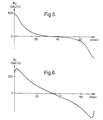
- Figure 5 shows a graph of magnetic flux density B across the aperture of a prior art device.
- the gradient of magnetic flux density in the centre of the aperture is shallow. This means that the device will not deflect a beam strongly.
- the gradient of magnetic flux density increases rapidly as the periphery of the aperture is approached. This graph represents the effect of magnetic flux concentrating around the coils.
- FIG. 6 shows a graph of magnetic flux density across the aperture of device 10. The effect of the inserts is clearly visible in that the gradient of magnetic flux density in the centre of the aperture is higher than before and across the aperture the gradient is more constant.
- the magnetic flux density shown in Figures 5 and 6 is from the edge of the body 12 adjacent to one coil 24, 26 to the edge of the body 12 adjacent to the other coil 24, 26 along a centre line in the body.
- the y-axis in these figures represents a value B y .
- the magnetic flux density caused by the coils can be resolved into two components, B x and B y .
- B y is that component of the magnetic flux density which causes Faraday rotation, that is the part which is parallel to the direction of propagation of a microwave beam.
- the ferrite material chosen should exhibit low loss at the microwave frequencies concerned, satisfactory power handling capability, good temperature stability and a high value of saturation magnetisation.
- the latter criterion is important in order that the largest possible maximum beam deflection is obtained.
- a device in accordance with the invention is in a rapid-scanning antenna, for example in radar equipment, the device having the advantage over conventional antennae that no mechanical mechanism is involved. Alternatively, it may be used in a passive receiver for imaging and other applications. A further use for the device is as part of a transmitter and/or receiver in a communication system.
- the device may find application in any equipment wherein a quasi-optical transmission of microwave waves between components of the system is employed.
Landscapes
- Magnetic Resonance Imaging Apparatus (AREA)
- Variable-Direction Aerials And Aerial Arrays (AREA)
- Waveguide Aerials (AREA)
- Aerials With Secondary Devices (AREA)
- Microwave Tubes (AREA)
Claims (18)
- Gerät (10; 40; 50) zum Empfang eines ersten Bündels von Mikrowellenstrahlung (27) und zur Steuerung der Richtung eines entsprechenden zweiten Bündels vom Mikrowellenstrahlungs-Ausgang aus dem Gerät (10; 40; 50), wobei das zweite Bündel von dem ersten Bündel abgeleitet wird und das Gerät die folgenden Mittel aufweist:dadurch gekennzeichnet, daß der Körper (12) derart gefertigt ist, daß er einen räumlich nicht gleichförmigen magnetischen Widerstand aufweist, um einen größeren Anteil des Magnetfeldes so zu richten, daß dieser durch einen zentralen Bereich des Körpers (12; 42; 52) hindurchtritt, verglichen mit dem Fall, bei dem der Körper aus einem Material gefertigt ist, das dem Körper einen räumlich gleichförmigen magnetischen Widerstand verleiht.(a) einen Körper (12; 42; 52) zum Empfang des ersten Bündels (27) und zur Ausgabe des zweiten Bündels; und(b) Magnetisierungsmittel (20, 22, 24, 26), um ein Magnetfeld an den Körper (12; 42; 52) anzulegen, um das erste Bündel (27) durch den Körper (12; 42; 52) zu richten, und um das zweite Bündel zu erzeugen,
- Gerät (40) nach Anspruch 1, bei welchem der Körper (42) aus einer Materialzusammensetzung besteht, die sich räumlich von einem ersten Bereich (46) des Körpers, wo das erste Bündel im Betrieb empfangen wird, nach einem zweiten Bereich (46) des Körpers ändert, wo das zweite Bündel im Betrieb ausgegeben wird.
- Gerät (50) nach Anspruch 1, bei welchem der Körper (52) aus mehreren Schichten (54) besteht, die im Betrieb derart angeordnet sind, daß ihre Hauptflächen im wesentlichen senkrecht zur Ausbreitungsrichtung des ersten Bündels durch den Körper verlaufen.
- Gerät (10) nach Anspruch 3, bei welchem wenigstens eine der Schichten (54) sich von dem ersten Bereich nach dem zweiten Bereich erstreckt.
- Gerät (50) nach den Ansprüchen 3 oder 4, bei welchem der Körper (52) aus einer Materialzusammensetzung besteht, die sich räumlich in Richtung im wesentlichen senkrecht zur Ausbreitungsrichtung des ersten Bündels (27) durch den Körper (52) erstreckt, wenn das Gerät in Betrieb ist.
- Gerät (10; 40; 50) nach einem der vorhergehenden Ansprüche, bei welchem der Körper (12) aus einem Ferritmaterial hergestellt ist.
- Gerät (10; 40; 50) nach einem der vorhergehenden Ansprüche, bei welchem die Magnetisierungsmittel (20, 22, 24, 26) wenigstens einen Magnetisierungsaufbau aufweisen, um das Magnetfeld an den Körper (12, 42, 52) anzulegen.
- Gerät (10; 40; 50) nach Anspruch 7, bei welchem die Magnetisierungsmittel (20, 22, 24, 26) zwei Magnetisierungsaufbauten aufweisen.
- Gerät (10) nach Anspruch 7 oder 8, bei welchem die Magnetisierungsmittel (20, 22, 24, 26) räumlich auf gegenüberliegenden Seiten des Körpers (12) verteilt angeordnet sind.
- Gerät (10) nach einem der vorhergehenden Ansprüche, bei welchem die Magnetisierungsmittel (20, 22, 24, 26) im Betrieb zusammen mit dem Körper (12) bewirken, daß das Magnetfeld einen räumlichen magnetischen Gradienten aufweist, der mehr linear verläuft im Vergleich mit dem Fall, wo der Körper (12) aus einem Material hergestellt ist, das einen räumlich gleichförmigen magnetischen Widerstand hat.
- Gerät (10) nach einem der vorhergehenden Ansprüche, bei welchem der Körper (12) einen ersten Körperbereich (12) aufweist, der aus einem ersten Material hergestellt ist und wenigstens teilweise wenigstens einen Körperbereich (32, 34) umschließt, der aus einem zweiten Material hergestellt ist, das eine magnetische Permeabilität besitzt, die niedriger ist als die magnetische Permeabilität des ersten Materials.
- Gerät (40) nach Anspruch 11, bei welchem jeder Körperbereich (44, 46) sich von einem Aufbau der Magnetisierungsmittel zu einem oder mehreren weiteren Aufbauten der Magnetisierungsmittel erstreckt.
- Gerät (10) nach den Ansprüchen 11 oder 12, bei welchem die Magnetisierungsmittel zwei Magnetisierungsaufbauten (20, 22, 24, 26) aufweisen und jeder Körperbereich sich über mehr als die Hälfte der Distanz von einem Mittelpunkt (14) zwischen den beiden Aufbauten nach den Aufbauten (20, 22, 24, 26) erstreckt.
- Gerät (10) nach einem der Ansprüche 11 bis 13, bei welchem der wenigstens eine Körperbereich (32, 34) aus dem zweiten Material hergestellt ist und die Form eines Schlitzes in dem ersten Körperbereich aufweist, wobei der erste Körperbereich aus dem ersten Material hergestellt ist.
- Gerät (10) nach Anspruch 14, bei welchem der Schlitz (32, 34) verjüngt ausgebildet ist und nach dem zentralen Bereich (14) hin dünner wird.
- Gerät (10) nach einem der Ansprüche 11 bis 15, bei welchem das erste und zweite Material im wesentlichen die gleiche Dielektrizitätskonstante aufweisen.
- Gerät (10) nach einem der vorhergehenden Ansprüche, bei welchem die Magnetisierungsmittel zwei Aufbauten (20, 24; 22, 26) auf gegenüberliegenden Seiten des Körpers (12) aufweisen, wobei die Aufbauten Spulen (24, 26) auf Teilen (20, 22) aufweisen, die magnetisch mit dem Körper (12) gekoppelt sind, wobei die Teile (20, 22) aus einem Material bestehen, das gegenüber dem Material des Körpers (12) unterschiedlich ist.
- Gerät (10) nach Anspruch 17, bei welchem die Teile (20, 22) aus Metall gefertigt sind.
Applications Claiming Priority (3)
| Application Number | Priority Date | Filing Date | Title |
|---|---|---|---|
| GB9722720 | 1997-10-29 | ||
| GB9722720A GB2330950A (en) | 1997-10-29 | 1997-10-29 | Magnetic material arrangement for steering a radiation beam |
| PCT/GB1998/003187 WO1999022424A1 (en) | 1997-10-29 | 1998-10-26 | Electrical apparatus |
Publications (2)
| Publication Number | Publication Date |
|---|---|
| EP1027752A1 EP1027752A1 (de) | 2000-08-16 |
| EP1027752B1 true EP1027752B1 (de) | 2001-08-29 |
Family
ID=10821193
Family Applications (1)
| Application Number | Title | Priority Date | Filing Date |
|---|---|---|---|
| EP98949152A Expired - Lifetime EP1027752B1 (de) | 1997-10-29 | 1998-10-26 | Elektrisches gerät |
Country Status (9)
| Country | Link |
|---|---|
| US (1) | US6320551B1 (de) |
| EP (1) | EP1027752B1 (de) |
| JP (1) | JP4104820B2 (de) |
| AU (1) | AU9552698A (de) |
| CA (1) | CA2307768C (de) |
| DE (1) | DE69801514T2 (de) |
| ES (1) | ES2161547T3 (de) |
| GB (1) | GB2330950A (de) |
| WO (1) | WO1999022424A1 (de) |
Families Citing this family (4)
| Publication number | Priority date | Publication date | Assignee | Title |
|---|---|---|---|---|
| GB2332567B (en) * | 1997-12-17 | 2002-09-04 | Marconi Gec Ltd | Magnetic devices |
| DE19958750B4 (de) * | 1999-12-07 | 2006-08-24 | Robert Bosch Gmbh | Leckwellenantenne |
| US20110115674A1 (en) * | 2009-11-13 | 2011-05-19 | Bae Systems Information And Electronic Systems Integration Inc. | System and method for interrogating a target using polarized waves |
| US8072369B2 (en) * | 2009-11-13 | 2011-12-06 | Bae Systems Information And Electronic Systems Integration Inc. | System and method for interrogating a target using polarized waves |
Family Cites Families (5)
| Publication number | Priority date | Publication date | Assignee | Title |
|---|---|---|---|---|
| US2973516A (en) * | 1957-10-17 | 1961-02-28 | Gen Dynamics Corp | Scanning antenna using magneticallycontrolled internal ferrite wave refraction |
| US3369242A (en) * | 1964-11-24 | 1968-02-13 | Sylvania Electric Prod | Inertialess electromagnetic wave scanner |
| US4588994A (en) * | 1982-10-18 | 1986-05-13 | Hughes Aircraft Company | Continuous ferrite aperture for electronic scanning antennas |
| GB2253947A (en) * | 1991-03-22 | 1992-09-23 | Marconi Gec Ltd | Microwave beam-steering devices. |
| US5729239A (en) | 1995-08-31 | 1998-03-17 | The United States Of America As Represented By The Secretary Of The Navy | Voltage controlled ferroelectric lens phased array |
-
1997
- 1997-10-29 GB GB9722720A patent/GB2330950A/en not_active Withdrawn
-
1998
- 1998-10-26 WO PCT/GB1998/003187 patent/WO1999022424A1/en not_active Ceased
- 1998-10-26 AU AU95526/98A patent/AU9552698A/en not_active Abandoned
- 1998-10-26 JP JP2000518428A patent/JP4104820B2/ja not_active Expired - Fee Related
- 1998-10-26 CA CA002307768A patent/CA2307768C/en not_active Expired - Fee Related
- 1998-10-26 ES ES98949152T patent/ES2161547T3/es not_active Expired - Lifetime
- 1998-10-26 DE DE69801514T patent/DE69801514T2/de not_active Expired - Lifetime
- 1998-10-26 EP EP98949152A patent/EP1027752B1/de not_active Expired - Lifetime
- 1998-10-26 US US09/530,498 patent/US6320551B1/en not_active Expired - Fee Related
Also Published As
| Publication number | Publication date |
|---|---|
| GB2330950A (en) | 1999-05-05 |
| JP2001522154A (ja) | 2001-11-13 |
| JP4104820B2 (ja) | 2008-06-18 |
| EP1027752A1 (de) | 2000-08-16 |
| DE69801514T2 (de) | 2002-05-29 |
| CA2307768C (en) | 2006-07-04 |
| WO1999022424A1 (en) | 1999-05-06 |
| GB9722720D0 (en) | 1998-04-15 |
| DE69801514D1 (de) | 2001-10-04 |
| CA2307768A1 (en) | 1999-05-06 |
| AU9552698A (en) | 1999-05-17 |
| ES2161547T3 (es) | 2001-12-01 |
| US6320551B1 (en) | 2001-11-20 |
Similar Documents
| Publication | Publication Date | Title |
|---|---|---|
| Gloeckler | Phased array for millimeter wave frequencies | |
| US7417587B2 (en) | Ferrite phase shifter and phase array radar system | |
| CA2315105C (en) | Magnetic beam deflection devices | |
| CA1264373A (en) | Flat wide - band antenna | |
| CA2081998A1 (en) | Polarization agility in an rf radiator module for use in a phased array | |
| Maheri et al. | Experimental studies of magnetically scannable leaky-wave antennas having a corrugated ferrite slab/dielectric layer structure | |
| US5223808A (en) | Planar ferrite phase shifter | |
| US3369242A (en) | Inertialess electromagnetic wave scanner | |
| AU567441B2 (en) | Continuous ferrite aperture for electronic scanning antennas | |
| US3626335A (en) | Phase-shifting means | |
| US3698008A (en) | Latchable, polarization-agile reciprocal phase shifter | |
| US3982213A (en) | Monolithic reciprocal latching ferrite phase shifter | |
| EP1027752B1 (de) | Elektrisches gerät | |
| JPS617703A (ja) | 位相調整可能な電力分配装置 | |
| US4691208A (en) | Ferrite waveguide scanning antenna | |
| US4502053A (en) | Circularly polarized electromagnetic-wave radiator | |
| US3445851A (en) | Polarization insensitive microwave energy phase shifter | |
| US3838363A (en) | Planar phase shifter for use in the microwave range | |
| EP0505040A1 (de) | Mikrowellenvorrichtungen zum Steuern der Richtung einer Strahlungskeule | |
| US5231411A (en) | One piece millimeter wave phase shifter/antenna | |
| US4443800A (en) | Polarization control element for phased array antennas | |
| US3448410A (en) | Broadband reciprocal dual meander line ferrite phase shifter | |
| US4201961A (en) | Unidirectional phase shifter | |
| Batchelor et al. | Scanned microstrip arrays using simple integrated ferrite phase shifters | |
| Sorensen et al. | Low-cost nonplanar microstrip-line ferrite phase shifter utilizing circular polarization |
Legal Events
| Date | Code | Title | Description |
|---|---|---|---|
| PUAI | Public reference made under article 153(3) epc to a published international application that has entered the european phase |
Free format text: ORIGINAL CODE: 0009012 |
|
| 17P | Request for examination filed |
Effective date: 20000511 |
|
| AK | Designated contracting states |
Kind code of ref document: A1 Designated state(s): DE ES FR GB IT SE |
|
| GRAG | Despatch of communication of intention to grant |
Free format text: ORIGINAL CODE: EPIDOS AGRA |
|
| GRAG | Despatch of communication of intention to grant |
Free format text: ORIGINAL CODE: EPIDOS AGRA |
|
| 17Q | First examination report despatched |
Effective date: 20001129 |
|
| GRAG | Despatch of communication of intention to grant |
Free format text: ORIGINAL CODE: EPIDOS AGRA |
|
| GRAH | Despatch of communication of intention to grant a patent |
Free format text: ORIGINAL CODE: EPIDOS IGRA |
|
| RAP1 | Party data changed (applicant data changed or rights of an application transferred) |
Owner name: BAE SYSTEMS (DEFENCE SYSTEMS) LIMITED |
|
| RAP1 | Party data changed (applicant data changed or rights of an application transferred) |
Owner name: BAE SYSTEMS ELECTRONICS LTD. |
|
| GRAH | Despatch of communication of intention to grant a patent |
Free format text: ORIGINAL CODE: EPIDOS IGRA |
|
| GRAA | (expected) grant |
Free format text: ORIGINAL CODE: 0009210 |
|
| AK | Designated contracting states |
Kind code of ref document: B1 Designated state(s): DE ES FR GB IT SE |
|
| ITF | It: translation for a ep patent filed | ||
| REF | Corresponds to: |
Ref document number: 69801514 Country of ref document: DE Date of ref document: 20011004 |
|
| ET | Fr: translation filed | ||
| REG | Reference to a national code |
Ref country code: ES Ref legal event code: FG2A Ref document number: 2161547 Country of ref document: ES Kind code of ref document: T3 |
|
| REG | Reference to a national code |
Ref country code: GB Ref legal event code: IF02 |
|
| PLBE | No opposition filed within time limit |
Free format text: ORIGINAL CODE: 0009261 |
|
| STAA | Information on the status of an ep patent application or granted ep patent |
Free format text: STATUS: NO OPPOSITION FILED WITHIN TIME LIMIT |
|
| 26N | No opposition filed | ||
| REG | Reference to a national code |
Ref country code: GB Ref legal event code: 732E |
|
| REG | Reference to a national code |
Ref country code: FR Ref legal event code: TP |
|
| PGFP | Annual fee paid to national office [announced via postgrant information from national office to epo] |
Ref country code: DE Payment date: 20101022 Year of fee payment: 13 |
|
| PGFP | Annual fee paid to national office [announced via postgrant information from national office to epo] |
Ref country code: GB Payment date: 20101021 Year of fee payment: 13 Ref country code: IT Payment date: 20101026 Year of fee payment: 13 |
|
| PGFP | Annual fee paid to national office [announced via postgrant information from national office to epo] |
Ref country code: SE Payment date: 20111021 Year of fee payment: 14 Ref country code: FR Payment date: 20111103 Year of fee payment: 14 Ref country code: ES Payment date: 20111021 Year of fee payment: 14 |
|
| GBPC | Gb: european patent ceased through non-payment of renewal fee |
Effective date: 20121026 |
|
| REG | Reference to a national code |
Ref country code: FR Ref legal event code: ST Effective date: 20130628 |
|
| PG25 | Lapsed in a contracting state [announced via postgrant information from national office to epo] |
Ref country code: DE Free format text: LAPSE BECAUSE OF NON-PAYMENT OF DUE FEES Effective date: 20130501 Ref country code: SE Free format text: LAPSE BECAUSE OF NON-PAYMENT OF DUE FEES Effective date: 20121027 Ref country code: GB Free format text: LAPSE BECAUSE OF NON-PAYMENT OF DUE FEES Effective date: 20121026 |
|
| REG | Reference to a national code |
Ref country code: DE Ref legal event code: R119 Ref document number: 69801514 Country of ref document: DE Effective date: 20130501 |
|
| PG25 | Lapsed in a contracting state [announced via postgrant information from national office to epo] |
Ref country code: IT Free format text: LAPSE BECAUSE OF NON-PAYMENT OF DUE FEES Effective date: 20121026 Ref country code: FR Free format text: LAPSE BECAUSE OF NON-PAYMENT OF DUE FEES Effective date: 20121031 |
|
| REG | Reference to a national code |
Ref country code: ES Ref legal event code: FD2A Effective date: 20140116 |
|
| PG25 | Lapsed in a contracting state [announced via postgrant information from national office to epo] |
Ref country code: ES Free format text: LAPSE BECAUSE OF NON-PAYMENT OF DUE FEES Effective date: 20121027 |