EP1027102B1 - Dsp-basierter herzschrittmacher mit verbesserter ereignisklassifizierung und beobachtung - Google Patents
Dsp-basierter herzschrittmacher mit verbesserter ereignisklassifizierung und beobachtung Download PDFInfo
- Publication number
- EP1027102B1 EP1027102B1 EP99969350A EP99969350A EP1027102B1 EP 1027102 B1 EP1027102 B1 EP 1027102B1 EP 99969350 A EP99969350 A EP 99969350A EP 99969350 A EP99969350 A EP 99969350A EP 1027102 B1 EP1027102 B1 EP 1027102B1
- Authority
- EP
- European Patent Office
- Prior art keywords
- signals
- signal
- slope
- parameters
- dsp
- Prior art date
- Legal status (The legal status is an assumption and is not a legal conclusion. Google has not performed a legal analysis and makes no representation as to the accuracy of the status listed.)
- Expired - Lifetime
Links
- 238000012544 monitoring process Methods 0.000 title 1
- 238000004458 analytical method Methods 0.000 claims description 35
- 238000012545 processing Methods 0.000 claims description 26
- 238000004422 calculation algorithm Methods 0.000 claims description 21
- 230000000747 cardiac effect Effects 0.000 claims description 21
- 230000001746 atrial effect Effects 0.000 claims description 13
- 230000002861 ventricular Effects 0.000 claims description 10
- 238000001514 detection method Methods 0.000 claims description 6
- 206010047289 Ventricular extrasystoles Diseases 0.000 claims description 5
- 238000006243 chemical reaction Methods 0.000 claims description 5
- 206010042602 Supraventricular extrasystoles Diseases 0.000 claims description 2
- 238000001914 filtration Methods 0.000 claims description 2
- 238000010586 diagram Methods 0.000 description 14
- 238000007635 classification algorithm Methods 0.000 description 7
- 230000006870 function Effects 0.000 description 6
- 230000004044 response Effects 0.000 description 6
- 210000002837 heart atrium Anatomy 0.000 description 5
- 208000028867 ischemia Diseases 0.000 description 5
- 238000000034 method Methods 0.000 description 5
- 230000009977 dual effect Effects 0.000 description 4
- 230000000694 effects Effects 0.000 description 4
- 206010019280 Heart failures Diseases 0.000 description 2
- 238000010420 art technique Methods 0.000 description 2
- 238000004364 calculation method Methods 0.000 description 2
- 238000004891 communication Methods 0.000 description 2
- 238000005516 engineering process Methods 0.000 description 2
- 230000000763 evoking effect Effects 0.000 description 2
- 210000005003 heart tissue Anatomy 0.000 description 2
- 239000003550 marker Substances 0.000 description 2
- 230000008569 process Effects 0.000 description 2
- 238000011374 additional therapy Methods 0.000 description 1
- 238000013459 approach Methods 0.000 description 1
- 230000005540 biological transmission Effects 0.000 description 1
- 230000008602 contraction Effects 0.000 description 1
- 239000003814 drug Substances 0.000 description 1
- 229940079593 drug Drugs 0.000 description 1
- 230000006872 improvement Effects 0.000 description 1
- 238000010348 incorporation Methods 0.000 description 1
- 230000010287 polarization Effects 0.000 description 1
- 238000005316 response function Methods 0.000 description 1
- 210000005241 right ventricle Anatomy 0.000 description 1
- 230000035945 sensitivity Effects 0.000 description 1
- 230000000638 stimulation Effects 0.000 description 1
- 210000001519 tissue Anatomy 0.000 description 1
- 230000002618 waking effect Effects 0.000 description 1
Images


Classifications
-
- A—HUMAN NECESSITIES
- A61—MEDICAL OR VETERINARY SCIENCE; HYGIENE
- A61N—ELECTROTHERAPY; MAGNETOTHERAPY; RADIATION THERAPY; ULTRASOUND THERAPY
- A61N1/00—Electrotherapy; Circuits therefor
- A61N1/18—Applying electric currents by contact electrodes
- A61N1/32—Applying electric currents by contact electrodes alternating or intermittent currents
- A61N1/36—Applying electric currents by contact electrodes alternating or intermittent currents for stimulation
- A61N1/362—Heart stimulators
- A61N1/3621—Heart stimulators for treating or preventing abnormally high heart rate
-
- Y—GENERAL TAGGING OF NEW TECHNOLOGICAL DEVELOPMENTS; GENERAL TAGGING OF CROSS-SECTIONAL TECHNOLOGIES SPANNING OVER SEVERAL SECTIONS OF THE IPC; TECHNICAL SUBJECTS COVERED BY FORMER USPC CROSS-REFERENCE ART COLLECTIONS [XRACs] AND DIGESTS
- Y10—TECHNICAL SUBJECTS COVERED BY FORMER USPC
- Y10S—TECHNICAL SUBJECTS COVERED BY FORMER USPC CROSS-REFERENCE ART COLLECTIONS [XRACs] AND DIGESTS
- Y10S128/00—Surgery
- Y10S128/901—Suppression of noise in electric signal
Definitions
- This invention relates to cardiac pacing systems having the capability of recognizing sensed signals, the recognition being based upon characteristics of the sensed signal and, more particularly, such systems which utilize digital signal processing for analysis of sensed signals in combination with a software-based decision algorithm.
- Implantable cardiac pacemakers have a great need to accurately process sensed signal information, so as to determine when a genuine cardiac signal has in fact been sensed, and then to accurately identify, or classify the signal. Separating cardiac signals from polarization effects and other noise artifacts has always been a substantial problem, and a great deal of effort has been placed on improving input circuits for this purpose. Additionally, it is recognized that it is important to be able to classify a sensed signal, e.g., determine whether it is a QRS, P-wave, far field R-wave (FFRW), or what. Many prior art techniques have been developed for signal classification, but improvement is still needed.
- one prior art technique is to establish a variable timing window, and classify the event in terms of the timing of the signal received during the window.
- early beats, ectopic signals, etc. can fool such a technique, and noise can still mask the signal which is sensed within the window.
- Other known techniques include morphology analysis, comparisons in the time and frequency domain, etc. While many of these techniques provide reasonably good results, they can involve considerable circuit complexity and frequently do not eliminate the probability of error due to detection of noise or other artifacts.
- DSP digital signal processing
- US-4,577,266 describes a programmable digital cardiac pacemaker, wherein parameter data stored in memory is used by digital filters for identifying various components of cardiac activity.
- DSP processing together with a microprocessor and an appropriate signal classification algorithm, provides a powerful tool for accurately sensing and classifying intracardiac signals.
- DSP-generated signal parameters can also be used to assess the state of the heart and changes such as ischemia, heart failures, etc.
- a cardiac pacing system having a pacemaker and lead means for inter-connecting said pacemaker and the patient's heart, said pacemaker having pulse means for generating pacing pulses and control means for controlling the operation of said pacemaker, said lead means having electrode means for delivering pacing pulses to a patient's heart and for sensing cardiac signals, said pacemaker having DSP means for amplifying and processing said intracardiac signals sensed by said electrode means, said DSP means comprising at least one DSP channel, said channel comprising:
- the DSP circuitry determines up to nine parameters for each analyzed signal, each parameter representing a predetermined characteristic of the signal.
- the DSP circuitry continuously filters the incoming signals and generates the slew rate, or slope of the signal from the filtered signal; and it compares each of the filtered and slope signals to a respective predetermined positive and negative threshold.
- a sense window of a predetermined time limit e.g., 50 ms, is started with the first threshold crossing, and a signal is deemed to be sensed only when it has crossed one filtered signal threshold and one slope threshold within the sense window.
- the DSP logic times out an analysis window of predetermined duration, e.g., 70 ms.
- the analysis window may be initiated at the time of the first threshold crossing; at the time of a "sense"; or at a software-generated time produced under control of the processor. For each of the filtered signal and the slope signals, a maximum and minimum value is obtained during the analysis window, and a time interval from signal sense to the maximum and minimum for each of these signals is obtained. Additionally, a signal window length from the first crossing of any one of the four thresholds to the last such crossing during the analysis window is generated, providing a ninth parameter.
- a separate DSP channel is used for sensing each respective type of signal, and for generating parameters corresponding to such signal.
- the parameters from each channel are transferred on a data bus to a microprocessor, which is software controlled to classify each sensed signal as a function of two or more of the DSP-generated parameters.
- the software includes a classification algorithm for each DSP channel, and each algorithm is programmable so that classification for the patient can be optimized for each signal type.
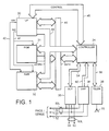
- FIG. 1 there is shown a functional block diagram of an implantable pacemaker of a type with which the present invention may be practiced. It is to be noted that Figure 1 is representative of such a pacemaker, and is not limiting in the actual architecture of the pacemaker. It is presented for the purpose of discussing data flow and, in particular, the position of a DSP chip and a microprocessor for purposes of sensing, analyzing and classifying sensed intracardiac signals. Accordingly, Figure 1 is considered to be exemplary rather than limiting with regard to the present invention. While the invention is disclosed as embodied in a pacemaker, it is likewise applicable to incorporation in a cardioverter, or combined cardioverter pacemaker, cardioverter defibrillator pacemaker, etc.
- the DSP chip has three channels, for respective processing of P, R and T wave signals.
- the primary elements of the apparatus illustrated in Fig. 1 are microprocessor 30, read only memory 31, random access memory 32, a digital controller 34, output amplifier 35, DSP circuitry 36, and a telemetry/programming unit 38.
- Read only memory 31 stores the basic programming for the device, including the primary instructions set defining the computations performed to derive the various timing intervals performed by the device.
- Random access memory 32 serves to store the values of variable control parameters, such as programmed pacing rate, pulse widths, pulse amplitudes, and so forth, which are programmed into the device by the physician. Reading from random access memory 32 and read only memory 31 is controlled by RD-line 41. Writing to random access memory 32 is controlled by WR-Line 42.
- Controller 34 performs all of the basic timing and control functions of the illustrative pacemaker device.
- Controller 34 includes at least one programmable timing counter, e.g., initiated on paced or sensed ventricular contractions, for timing out intervals thereafter. This timing counter is used to define the escape intervals for timing generation of pace pulses, as well as for timing the respective durations of the charge and recharge pulse portions of triphasic pulses.
- Controller 34 triggers output pulses to be generated and delivered from output stage 35, and it generates interrupts on control bus 46 for cyclically waking microprocessor 30 from its sleep state to allow it to perform the required functions.
- For a single chamber pacemaker output circuit 35 is coupled to electrodes 50 and 51 which are employed both for delivery of pacing pulses and for sensing of cardiac signals.
- Electrode 50 is typically located on the distal tip end of an endocardial lead 50L, and for ventricular pacing is preferably placed in the apex of the right ventricle; for atrial pacing, of course, it is placed in the patient's atrium. Electrode 51 is preferably a ring electrode, as used with a bipolar lead. Electrode 52 represents the pacemaker housing, which may be used as the indifferent electrode for selected unipolar pacing and/or sensing operations. Of course, for a dual or multi-chamber pacing system, additional electrodes are employed. For example, electrodes 59,60 carried by lead 60L may be used for pacing and sensing in the atrium, while electrodes 50,51 are used in the ventricle. Output circuit 35 is controlled by controller 34 through bus 54 to determine the amplitude and pulse width of the pulse to be delivered and to determine which electrode pair is to be employed to deliver the pulse.
- Cardiac signals are sensed at a desired pair or pairs of electrodes; bipolar and/or unipolar sensing may be used.
- a unipolar lead in the atrium and a unipolar lead in the ventricle are used, e.g., the signals are picked up at electrodes 50,59.
- Sense signals are inputted to DSP block 36, which comprises a number of signal processing channels corresponding to signals of interest. For example, in a dual chamber pacemaker which incorporates P wave processing either for rate control, capture detection or any other reason, there are three channels for respective signal processing of the P, R and T waves.
- the data resulting from the digital signal processing is transmitted via bus 60 through controller 34 and bus 46 to microprocessor 30, for the signal classification operations, as well as any other necessary calculations.
- telemetry/control block 38 External control of the implanted device is accomplished via telemetry/control block 38, which allows communication between the implanted device and an external programmer (not shown). Radio communication is typically employed via antenna 55.
- Appropriate telemetry/programming systems are well known in the art; the present invention is workable with any conventional telemetry/programming circuitry.
- Information entering the pacemaker from the programmer is passed to controller 34 via bus 56.
- information from the pacemaker is provided to the telemetry block 38 via bus 56, for transmission to the external programmer.
- the classification algorithms for processing the parameters generated by each DSP channel can be re-programmed in a known manner.
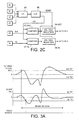
- FIG. 2A there is shown a diagram representing the primary components of a DSP chip 36.
- the chip is manufactured with a chip area of about 20 mm 2 , and draws about 0.7-1.5 microamps per channel.
- Figure 2A shows an atrial (A) or ventricular (V) signal introduced into a DSP channel; it is to be understood that as many similar channels as desired are provided for signal processing of respective signals.
- the signal still in analog form, is first passed through an amplifier 62, having a filter characteristic of about 0.7 to 500 Hz.
- the amplified analog signal is passed into A/D converter 64, for generation of a digital signal.
- the A/D conversion is suitably done by a delta-sigma modulator, as shown in Figure 2B , followed by a decimater to provide typically 8-bit bytes at 1.6 ms intervals.
- the digital signal from block 64 is connected to digital filter 65 which is suitably a digital bandpass filter having a characteristic to eliminate low frequency signal components and the offset of the converter, as well as to take out high frequency artifacts.
- the output of block 65 referred to as SIG in Figure 3A , is connected to sense block 66.
- Sense block 66 obtains the slew rate, or slope of the signal, also hereafter referred to as the SL signal, and then compares both the SIG and SL signals to plus and minus threshold voltages to derive a "sense" signal.
- the output of digital filter 65 in one embodiment, is connected to a series of three registers, Registers 81, 82 and 83 being cascaded so that at each sample the digital signal in Register 1 is passed to Register 2, and the signal in Register 2 is passed to Register 3.
- the difference is then obtained at difference circuit 84, by taking the difference between either Register 1 - which holds the SIG signal - and Register 2; or the difference between Register 1 and Register 3.
- the SIG signal is compared with a positive voltage threshold
- the SIG signal is compared with a negative threshold signal.
- OR gate 89 Whenever the SIG exceeds either threshold, an output is passed through OR gate 89, and triggers generation of a window signal of 50 ms duration, shown at block 90.
- the difference or SL signal from block 84 is compared at 87 with a positive threshold and at 88 with a minus threshold, and if either threshold is exceeded, a signal is passed through OR gate 91 to window circuit 92.
- AND circuit 93 produces an output, which is recognized at 94 as a sensed event.
- the upper curve represents the filtered signal (SIG), and the lower signal represents a corresponding slope (SL) signal corresponding to an event which is to be sensed and classified.
- SIG filtered signal
- SL slope
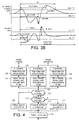
- FIG. 2C there is shown a block diagram of an illustrative circuit corresponding to block 68 of Figure 2A , titled "form analys”.
- This block is where the DSP circuitry operates during the 70 ms analysis window to extract parameters from the signal under examination, which parameters are shown in Figure 3B .
- the analysis window When the analysis window is active, the SIG and SL values are operated on to obtain the signal parameters that are illustrated in Figure 3B .
- the filtered signal as illustrated in Figure 3B , both maximum and minimum values of SIG during the analysis window are obtained; the positive value is indicated as SIGmax and the negative as SIGmin.
- SIG Dmax The time from sense to SIGmax
- SIG Dmin the time from sense to SIGmin.
- values of SLmax and SLmin are determined, and the time from sense to each is found, namely SL Dmax and SL Dmin. Additionally, the time from first crossing of a threshold to the last crossing of a threshold is determined as labelled W; in this example W is from the first SIG crossing of the positive threshold to the last SIG crossing of the SIG positive threshold.
- the analysis window is initiated by the first occurrence of the event signal crossing one of the four thresholds.
- the inputs from comparators 85-88, as seen in Figure 2B are gated through OR circuit 95, and the first signal gated through initiates the generation of a window signal at circuit 96.
- the analysis window signal is connected to enable compare circuits 97-SIG and 97-SL.
- Circuit 97-SIG compares the SIG signal from block 65 with the current values of MIN/MAX registers 98-SIG; and circuit 97-SL compares the SL signal from block 84 with the current values of MIN/MAX registers 98-SL.
- the 8-register set, 98-SIG and 98-SL is reset at the start of the analysis window.
- the SIG and SL signal samples are separately compared to four respective registers, which correspond to that signal's four respective parameters as seen in Figure 3B ; and new parameter values are written into the corresponding registers.
- W is recorded as the time from the first crossing of a threshold to the last threshold crossing.
- the parameters are obtained by the DSP circuitry form by continuous operation on each byte of data from the time of the first threshold crossing until the end of the analysis window.
- the parameters are provided on data bus 60, which is communicated directly through onto bus 46 to microprocessor 30.
- the output of each of blocks 64, 65, 66 and 68 is connected through I/O interface 70 to a bus 72, which can either connect to data bus 60 or to program registers 75.
- the registers connect to blocks 62, 64, 65, 66 and 68, and serve a variety of purposes, such as programming amplifier sensitivity, programming threshold levels of the sense block, etc.
- an incoming analog signal which has been sensed in the atrium is inputted to the A channel of the DSP chip.
- the A channel is programmed with thresholds corresponding to signals sensed in the atrium.
- the received signal is operated on as discussed above, namely it is amplified; converted from A to D; digitally filtered; the slope signal is obtained; a sense signal is obtained if a signal is in fact present; and the form analysis is performed to obtain the parameters, e.g., up to nine parameters, as set forth above.
- a sense signal and the parameters are sent to the microprocessor 30, as indicated at block 101. If the signal has come from the ventricle, it is connected to the R channel (102) of the DSP chip and also to the T channel (104).
- the R channel is programmed with thresholds appropriate to R waves, and performs the same DSP functions as the A channel; the resulting sense signal and parameters are sent to the microprocessor, as shown at block 103.
- the T channel is programmed with thresholds corresponding to T waves, and likewise performs the functions as shown in Figure 2A , and thereafter sends data to the microprocessor as shown at 105.
- the microprocessor determines the channel from which the data has been sent, at 107 and 110, and selects the corresponding algorithm for signal classification.
- the data is operated on with an atrial signal algorithm, shown at 108; for a signal from the R channel, the data is operated on with an R wave signal algorithm 111; and for a signal from the T channel, the signal is operated on by T wave algorithm 112.
- the microprocessor goes on to the appropriate event handling at 114, i.e., predetermined logical steps follow the detection of each respective type of signal. See, for example, U.S. Patent No. 5,782,887, issued July 21, 1998 , which provides examples of V sense, A sense and T wave event handling.
- each microprocessor classification algorithm is programmable. For a given channel which is to process atrial or ventricular signals, any combination of the nine parameters can be utilized, and they are weighted relative to each other. Thus, there is provided a flexibility, wherein the DSP chip very efficiently obtains the signal parameter data, while the software algorithm for each respective channel is optimally programmed to carry out the calculations for determining signal classification.
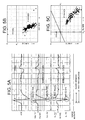
- FIG. 5A-5D there is illustrated the operation of a channel of the DSP circuitry 36, e.g., A channel 100 as shown in Figure 4 , in providing parameters of an atrial signal in order to distinguish FFRWs from P waves.
- Figure 5A presents a series of curves.
- the top curve represents an unipolar digitized atrial signal, showing P wave and FFRW portions.
- the second curve represents the filter output, or SIG signal, relative to a negative threshold of 0.5 mV and a positive threshold of 0.5mv; and illustrates minimum and maximum amplitude points.
- the third curve is the derived slope (SL) curve, with an indication of a negative threshold of 0.5 mV and a positive threshold of 0.5 mv.
- the sense signal the 50 ms sense window and 70 ms analysis window are indicated.
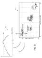
- Figure 5B is a plot of SIGmin and SIGmax signals, for a plurality of processed signals. It is seen from this that most of the signals have a SIGmin value which is below a predetermined horizontal line, i.e., below a predetermined value of SIGmin shown as Ko.
- Figure 5C data from the same signals is plotted, comparing SLmax with SLmin. In this case, it is seen that P waves fall below a horizontal line shown as K1, and to the right of vertical line K2. That is, signals meeting these criteria have a characteristic of P waves, whereas signals that do not have a characteristic of FFRWs.
- P waves can be distinguished from FFRWs with great confidence.
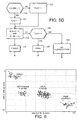
- Fig. 5D This is shown in the flow diagram of Fig. 5D , which is carried out by the microprocessor, e.g., block 108 of Figure 4 .
- the flag is set equal to 1, meaning that the analysis of the SIG signal alone suggests a P wave. If no, at 152 the flag is set equal to 0, corresponding to an initial analysis of an FFRW.
- the SL signal is compared to the SL criteria; if SLmax is less than K1, and SLmin is greater than K2, then at block 155 the signal is classified as a P wave.
- the routine goes to 156 and inspects the flag to recall the outcome of the SIG analysis. If the flag is set to 0, then both the SIG and SL signals indicate an FFRW, and at 157 the signal is classified is an FFRW. However, if the flag had been set to 1, the result is ambiguous, and at 158 it is determined that there is no event classification.
- PACs commonly have slope parameters different from normal sinus P waves, such that they can be distinguished by processing of a selected combination of the nine available parameters.
- Figures 7A, 7B , 7C there is illustrated the use of the invention for distinguishing PVCs from normal conducted R waves.
- Figure 7A illustrates ventricular signal data, plotting SIGmin against SIGmax, while Figure 7B plots SLmin against SLmax.
- Figures 7A and 7B suggest criteria for distinguishing a PVC from a conducted R wave, which criteria are utilized in the algorithm of Figure 7C .
- SIGmax is greater than a constant X, this suggests the probability of a PVC. If the comparison is positive, the routine goes to block 121 and compares the value of SLmin with the constant Y.
- FIG. 8A there is illustrated the use of the combined DSP and software techniques of this invention with combipolar pacemaker sensing.
- this arrangement essentially provides bipolar differential sensing by means of an atrial unipolar lead and a ventricular unipolar lead.
- This arrangement is known to combine the advantages of bipolar sensing and unipolar leads, providing less interference by extraneous noise, and reduced sensing of myopotentials, FFRWs and other artifacts.
- the combined signals from the atrial and ventricular leads are inputted into channel block 130, designated P + R DSP channel.
- the signal from the ventricular lead is inputted into the R DSP channel 134.
- the combined P + R sense and parameter signals are outputted from channel 130 and operated on by a P/R sense algorithm 132, which classifies the signal as a P wave or an R wave.
- the sense and parameter signals from the R channel 134 are operated on by an R sense algorithm 136. Signals classified by either algorithm are sent for event handling. It is seen in Figure 8B that P waves can be clearly demarcated from R waves by the diagonal line, which represents the sum of the magnitude of SLmin and SLmax. For this data, this sum is equal to 170, such that for any signal where the combined magnitude is less than 170, a P wave is indicated; whereas if the combined magnitudes are greater than 170, an R wave is indicated. As indicated at block 140 of Fig.
- the algorithm in analyzing a sensed signal from the P + R channel, the algorithm first gets the sum of the magnitudes of the two slope parameters, at 140. At 142, it is determined whether this sum, indicated as Y, is greater than 170. If yes, the signal is classified as an R wave at 144; if no, it is classified as a P wave at 146. It is to be understood that while Figure 8C presents logic steps limited to analyzing the slope parameters, the algorithm may additionally utilize any of the other parameters as shown in Figure 3 . Of course, where one parameter comparison, such as suggested by Figure 8C , is seen to predict with a high confidence, it is weighted more than other comparisons. However, in general, one or more criteria can be combined on a logical AND or OR basis in the classification algorithm.
- the present invention may further be used to assess the condition of heart tissue and, in particular, to detect and/or respond to the presence of ischemia.
- the present invention may perform such additional functionalities by viewing the trend or movement of one or more parameters with respect to time or rate. These parameters may include for field R-waves as well as QRS width slope or evoked response slope. The use of such parameters is made especially simple through the DSP signal processing approach discussed above.
- the use of such parameters for ischemia detection is shown as an example in figure 9 .
- signal parameters such as min slope and max slope may be used to classify signals such as R-wave far waves, retrograde P-waves, etc.
- FIG. 9-2 is an example showing the movement of far field R-waves over time. As seen over time, the far field R-wave index rises until it crosses a predetermined threshold PDT at time T0 . The crossing of such thresholds may be used for a variety of activities including, the storage of detected QRS signals and related information such as activity for later analysis.
- ischemia may be sensed.
Landscapes
- Health & Medical Sciences (AREA)
- Cardiology (AREA)
- Heart & Thoracic Surgery (AREA)
- Engineering & Computer Science (AREA)
- Biomedical Technology (AREA)
- Nuclear Medicine, Radiotherapy & Molecular Imaging (AREA)
- Radiology & Medical Imaging (AREA)
- Life Sciences & Earth Sciences (AREA)
- Animal Behavior & Ethology (AREA)
- General Health & Medical Sciences (AREA)
- Public Health (AREA)
- Veterinary Medicine (AREA)
- Electrotherapy Devices (AREA)
- Measurement And Recording Of Electrical Phenomena And Electrical Characteristics Of The Living Body (AREA)
Claims (12)
- Herzschrittmacher- bzw. -stimulationssystem mit einem Schrittmacher und Leitungsmitteln (50L, 60L) zum Verbinden des Schrittmachers mit dem Herzen des Patienten, wobei der Schrittmacher Pulsmittel zum Erzeugen von Stimulationspulsen und Steuermittel (34) zum Steuern des Betriebs des Schrittmachers aufweist, wobei die Leitungsmittel (50L, 60L) Elektrodenmittel (50, 51, 59, 60) zur Abgabe von Stimulationspulsen an ein Herz eines Patienten und zum Erfassen von Herzsignalen aufweisen, und wobei der Schrittmacher DSP-Mittel (36) zum Verstärken und Verarbeiten der Herzsignale, die durch die Elektrodenmittel erfasst werden, aufweist, wobei die DSP-Mittel wenigstens einen DSP-Kanal aufweisen, wobei der Kanal aufweist:Konvertierungs- bzw. Wandelmittel (64) zum Konvertieren der empfangenen verstärkten Signale in digitale Signale;digitale Filtermittel (65) zum Filtern der konvertierten Signale, um gefilterte Signale bereitzustellen;Steigungs- bzw. Neigungsmittel zum Arbeiten mit bzw. Einwirken auf die gefilterten Signale, um Steigungs- bzw. Neigungssignale, die bezüglich der Steigung bzw. Neigung der gefilterten Signale repräsentativ sind, bereitzustellen;Erfassungs- bzw. Messmittel (66) zum Bestimmen aus den gefilterten Signalen und den Steigungssignalen, wann immer bzw. wenn ein Herzereignis bestimmt wird, und der Erfassungszeit jeder Bestimmung;Analysefenstermittel um einen Timeout für ein Analysefenster von vorbestimmter Dauer, der auf die Erfassungszeit folgt, zu setzen bzw. durchzuführen;Parametermittel zum Verarbeiten der gefilterten Signale und der Steigungssignale während des Analysefensters und zum Erzeugen einer Anzahl jeweiliger Parameter aus den Signalen aus bzw. auf Grundlage der Verarbeitung; undwobei der Schrittmacher ferner Klassifizierungsmittel zum Empfangen der Parameter von den DSP-Mitteln und zum Klassifizieren jedes Signals als einer Funktion der Parameter aufweist; dadurch gekennzeichnet, dass
der Schrittmacher einen Mikroprozessor aufweist und die Klassifizierungsmittel den Mikroprozessor und einen Algorithmus zum Arbeiten mit bzw. Einwirken auf die Parameter aufweisen;
wobei die Elektrodenmittel Mittel zum Erfassen einer Anzahl jeweiliger Herzsignale aufweisen, und wobei die DSP-Mittel eine Anzahl der Kanäle aufweisen, wobei jeder Kanal einem jeweiligen Charakteristikum bzw. Kennzeichen der Herzsignale, die zu klassifizieren sind, entspricht, und wobei die Klassifizierungsmittel eine Anzahl jeweiliger programmierbarer Algorithmen zum Verarbeiten der durch jeden Kanal erzeugten Parameter aufweisen und programmiert sind, die Charakteristika, denen der jeweiligen Kanal entspricht, zu identifizieren. - System nach Anspruch 1, bei dem die Konvertierungsmittel eine Delta-Sigma-Modulatorschaltung aufweisen und wobei die DSP-Mittel ferner Verbindungsmittel zur Verbindung der Konvertierungsmittel, der digitalen Filtermittel, der Steigungsmittel, der Erfassungsmittel und der Parametermittel aufweisen.
- System nach Anspruch 1, bei dem die Parametermittel Mittel zum Ableiten von vier Parametern aus dem gefilterten Signal während jedes Analysefensters und zum Ableiten vier jeweiliger Parameter aus dem Neigungssignal während jedes Analysefensters aufweisen, und bei dem die Klassifizierungsmittel Mittel zum Klassifizieren jedes erfassten Signals als einer Funktion der vier Signalparameter und der vier Steigungsparameter aufweisen.
- System nach Anspruch 3, bei dem die Parametermittel Mittel zum Ableiten einer Signaldauer bzw. -länge als einer Funktion des Vergleichens der gefilterten Signale und der Steigungssignale mit vorbestimmten Grenzwertkriterien aufweisen.
- System nach Anspruch 1, bei dem die Erfassungsmittel Mittel zum Vergleichen der gefilterten Signale mit wenigstens einem vorbestimmten Grenzwert zum Vergleichen der Steigungssignale mit wenigstens einem anderen vorbestimmten Grenzwert aufweisen.
- System nach Anspruch 5, bei dem die Erfassungsmittel Mittel aufweisen, um zu bestimmen, wann in einem vorbestimmten Zeitintervall die Größe des gefilterten Signals den einen vorbestimmten Grenzwert überschritten hat und die Größe der Steigungssignale den anderen Grenzwert überschritten hat.
- System nach Anspruch 1, bei dem die Parametermittel Mittel aufweisen, die während des Analysefensters zum Bestimmen eines Minimal- und Maximalwertes der gefilterten Signale und der Steigungssignale in Betrieb sind.
- System nach Anspruch 7, bei dem die Elektrodenmittel Mittel zum Erfassen atrialer Signale aufweisen und die Klassifizierungsmittel Mittel zum Unterscheiden von P-Wellen und FFRS-Wellen als einer Funktion der Minimal- und Maximalwerte für die gefilterten Signale aufweisen.
- System nach Anspruch 8, bei dem die Klassifizierungsmittel Mittel zum Unterscheiden von P-Wellen und FFRS-Wellen als einer Funktion der Summe der absoluten Steigungsmaximal- und -minimalwerte während des Analysefensters aufweisen.
- System nach Anspruch 8, bei dem die Klassifizierungsmittel gespeicherte Kriterien aufweisen, die in Beziehung zu retrograden P-Wellen stehen, und einen Softwarealgorithmus zum Unterscheiden von retograden P-Wellen von natürlichen sinusförmigen P-Wellen bzw. P-Sinuswellen durch Vergleichen der Minimal- und Maximalwerte mit den Kriterien aufweisen.
- System nach Anspruch 8, bei dem die Klassifizierungsmittel Mittel zum Unterscheiden von FFRWen, retrograden P-Wellen, PACs und sinusförmigen P-Wellen aufweisen.
- System nach Anspruch 7, bei dem die Elektrodenmittel Mittel zum Erfassen ventrikulärer Signale aufweisen und bei dem die Klassifizierungsmittel Mittel zum Klassifizieren von PVCs aufweisen.
Applications Claiming Priority (3)
| Application Number | Priority Date | Filing Date | Title |
|---|---|---|---|
| US09/158,566 US6029087A (en) | 1998-09-22 | 1998-09-22 | Cardiac pacing system with improved physiological event classification based on DSP |
| US159566 | 1998-09-22 | ||
| PCT/EP1999/006610 WO2000016852A1 (en) | 1998-09-22 | 1999-09-08 | Dsp-based pacemaker with improved event classification and monitoring |
Publications (2)
| Publication Number | Publication Date |
|---|---|
| EP1027102A1 EP1027102A1 (de) | 2000-08-16 |
| EP1027102B1 true EP1027102B1 (de) | 2008-09-03 |
Family
ID=22568727
Family Applications (1)
| Application Number | Title | Priority Date | Filing Date |
|---|---|---|---|
| EP99969350A Expired - Lifetime EP1027102B1 (de) | 1998-09-22 | 1999-09-08 | Dsp-basierter herzschrittmacher mit verbesserter ereignisklassifizierung und beobachtung |
Country Status (4)
| Country | Link |
|---|---|
| US (1) | US6029087A (de) |
| EP (1) | EP1027102B1 (de) |
| DE (1) | DE69939456D1 (de) |
| WO (1) | WO2000016852A1 (de) |
Families Citing this family (74)
| Publication number | Priority date | Publication date | Assignee | Title |
|---|---|---|---|---|
| US6324426B1 (en) | 1988-04-28 | 2001-11-27 | Medtronic, Inc. | Power consumption reduction in medical devices employing multiple supply voltages and clock frequency control |
| US8255047B1 (en) * | 1998-09-22 | 2012-08-28 | Medtronic, Inc | Cardiac pacing system with improved physiological event classification and heart monitoring based on DSP |
| US6438422B1 (en) * | 1998-10-28 | 2002-08-20 | Medtronic, Inc. | Power dissipation reduction in medical devices using adiabatic logic |
| US6496729B2 (en) | 1998-10-28 | 2002-12-17 | Medtronic, Inc. | Power consumption reduction in medical devices employing multiple supply voltages and clock frequency control |
| US6516225B1 (en) | 1999-12-28 | 2003-02-04 | Pacesetter, Inc. | System and method for distinguishing electrical events originating in the atria from far-field electrical events originating in the ventricles as detected by an implantable medical device |
| DE60020514T2 (de) | 1999-12-28 | 2006-05-04 | Pacesetter, Inc., Sylmar | Verfahren zur Unterscheidung von im Herzen erfassten elektrischen Ereignissen und entsprechendes System |
| US6415181B1 (en) * | 2000-02-25 | 2002-07-02 | Medtronic, Inc. | Implantable medical device incorporating adiabatic clock-powered logic |
| DE10017620A1 (de) * | 2000-04-01 | 2001-10-04 | Biotronik Mess & Therapieg | Vorrichtung zur Verarbeitung physiologischer Signale |
| US6925328B2 (en) | 2000-04-20 | 2005-08-02 | Biophan Technologies, Inc. | MRI-compatible implantable device |
| US8527046B2 (en) | 2000-04-20 | 2013-09-03 | Medtronic, Inc. | MRI-compatible implantable device |
| US6795730B2 (en) | 2000-04-20 | 2004-09-21 | Biophan Technologies, Inc. | MRI-resistant implantable device |
| US6556859B1 (en) | 2000-04-24 | 2003-04-29 | Medtronic, Inc. | System and method for classifying sensed atrial events in a cardiac pacing system |
| US6434426B1 (en) | 2000-04-27 | 2002-08-13 | Medtronic Inc. | Method and system for determining a noise floor in a cardiac pacing system |
| US20020103505A1 (en) * | 2001-02-01 | 2002-08-01 | Medtronic, Inc. | Custom manufacturing of implantable medical devices |
| US6829509B1 (en) | 2001-02-20 | 2004-12-07 | Biophan Technologies, Inc. | Electromagnetic interference immune tissue invasive system |
| US20020116029A1 (en) | 2001-02-20 | 2002-08-22 | Victor Miller | MRI-compatible pacemaker with power carrying photonic catheter and isolated pulse generating electronics providing VOO functionality |
| US6615083B2 (en) | 2001-04-27 | 2003-09-02 | Medtronic, Inc. | Implantable medical device system with sensor for hemodynamic stability and method of use |
| DE10136641A1 (de) * | 2001-07-20 | 2003-02-06 | Biotronik Mess & Therapieg | Zweikammer-Herzschrittmacher |
| US7054686B2 (en) * | 2001-08-30 | 2006-05-30 | Biophan Technologies, Inc. | Pulsewidth electrical stimulation |
| US6731979B2 (en) | 2001-08-30 | 2004-05-04 | Biophan Technologies Inc. | Pulse width cardiac pacing apparatus |
| US7027861B2 (en) | 2001-10-09 | 2006-04-11 | Medtronic, Inc. | Method and apparatus for affecting atrial defibrillation with bi-atrial pacing |
| US6695790B2 (en) | 2001-10-26 | 2004-02-24 | Medtronic, Inc. | Method and system for determining kidney failure |
| US6731980B1 (en) | 2001-10-29 | 2004-05-04 | Pacesetter, Inc. | System and method for automatically setting a pre-ventricular atrial blanking period |
| WO2003037399A2 (en) * | 2001-10-31 | 2003-05-08 | Biophan Technologies, Inc. | Hermetic component housing for photonic catheter |
| US6650931B1 (en) * | 2001-11-14 | 2003-11-18 | Pacesetter, Inc. | System and method of automatically determining the onsets and ends of cardiac events and far-field signals |
| US6836682B2 (en) | 2001-11-16 | 2004-12-28 | Medtronic, Inc. | Rate responsive pacing system with QT sensor based on intrinsic QT data |
| US6671549B2 (en) | 2001-11-16 | 2003-12-30 | Medtronic, Inc. | Pacemaker utilizing QT dynamics to diagnose heart failure |
| US6745076B2 (en) | 2001-11-16 | 2004-06-01 | Medtronic, Inc. | Implantable medical device with autosensitivity algorithm for controlling sensing of cardiac signals |
| US7248921B2 (en) | 2003-06-02 | 2007-07-24 | Cameron Health, Inc. | Method and devices for performing cardiac waveform appraisal |
| AU2002302003B2 (en) * | 2001-11-28 | 2008-05-22 | Cardanal Pty Ltd | Method and system for processing electrocardial signals |
| US6968236B2 (en) | 2002-01-28 | 2005-11-22 | Biophan Technologies, Inc. | Ceramic cardiac electrodes |
| US6711440B2 (en) | 2002-04-11 | 2004-03-23 | Biophan Technologies, Inc. | MRI-compatible medical device with passive generation of optical sensing signals |
| AU2013202238B2 (en) * | 2002-04-19 | 2015-01-29 | Trading Technologies International, Inc. | Trading tools for electronic trading |
| US6725092B2 (en) | 2002-04-25 | 2004-04-20 | Biophan Technologies, Inc. | Electromagnetic radiation immune medical assist device adapter |
| US6925322B2 (en) * | 2002-07-25 | 2005-08-02 | Biophan Technologies, Inc. | Optical MRI catheter system |
| US7162300B2 (en) * | 2003-01-13 | 2007-01-09 | Medtronic, Inc. | Synchronized atrial anti-tachy pacing system and method |
| US7558626B2 (en) * | 2003-04-23 | 2009-07-07 | Medtronic, Inc. | Cardiac resynchronization via left ventricular pacing |
| US20040215238A1 (en) | 2003-04-24 | 2004-10-28 | Van Dam Peter M. | Pacemaker with improved capability for detecting onset of tachyarrhythmias and heart failure |
| US20040215276A1 (en) * | 2003-04-25 | 2004-10-28 | Patrick Scholten | Form analysis to detect evoked response |
| US7930026B2 (en) * | 2003-04-25 | 2011-04-19 | Medtronic, Inc. | Monitoring QRS complex to identify left ventricular dysfunction |
| US7734346B2 (en) * | 2003-04-25 | 2010-06-08 | Medtronic, Inc. | Identification of premature atrial contractions that trigger arrhythmia |
| US20060167366A1 (en) * | 2003-05-07 | 2006-07-27 | Seijiro Tomita | Method and apparatus for extracting biological signal such as heartbeat or respiration |
| US7127233B2 (en) * | 2003-07-31 | 2006-10-24 | Metro One Telecommunications, Inc. | Technique for controlling fraudulent use of a telecommunication service including information assistance |
| US7620446B2 (en) | 2003-07-31 | 2009-11-17 | Medtronic, Inc. | Monitoring P-waves to detect degradation of atrial myocardium |
| US7272434B2 (en) * | 2004-08-13 | 2007-09-18 | Boston Scientific Scimed, Inc. | Automatic post-pacing interval measurement |
| US7896807B2 (en) * | 2004-10-29 | 2011-03-01 | Worcester Polytechnic Institute | Multi-channel electrophysiologic signal data acquisition system on an integrated circuit |
| US8108046B2 (en) | 2004-12-17 | 2012-01-31 | Medtronic, Inc. | System and method for using cardiac events to trigger therapy for treating nervous system disorders |
| US8485979B2 (en) * | 2004-12-17 | 2013-07-16 | Medtronic, Inc. | System and method for monitoring or treating nervous system disorders |
| US8108038B2 (en) * | 2004-12-17 | 2012-01-31 | Medtronic, Inc. | System and method for segmenting a cardiac signal based on brain activity |
| US8112148B2 (en) * | 2004-12-17 | 2012-02-07 | Medtronic, Inc. | System and method for monitoring cardiac signal activity in patients with nervous system disorders |
| US8214035B2 (en) | 2004-12-17 | 2012-07-03 | Medtronic, Inc. | System and method for utilizing brain state information to modulate cardiac therapy |
| US8209019B2 (en) | 2004-12-17 | 2012-06-26 | Medtronic, Inc. | System and method for utilizing brain state information to modulate cardiac therapy |
| US8112153B2 (en) * | 2004-12-17 | 2012-02-07 | Medtronic, Inc. | System and method for monitoring or treating nervous system disorders |
| EP1833557B1 (de) * | 2004-12-17 | 2011-01-19 | Medtronic, Inc. | System zur überwachung oder behandlung von erkrankungen des nervensystems |
| US8209009B2 (en) * | 2004-12-17 | 2012-06-26 | Medtronic, Inc. | System and method for segmenting a cardiac signal based on brain stimulation |
| US20070239060A1 (en) * | 2004-12-17 | 2007-10-11 | Medtronic, Inc. | System and method for regulating cardiac triggered therapy to the brain |
| US7381215B2 (en) | 2005-01-21 | 2008-06-03 | Medtronic, Inc. | System and method for determining an effectiveness of a ventricular pacing protocol for an implantable medical device |
| EP1848502B1 (de) | 2005-01-21 | 2014-03-12 | Medtronic, Inc. | Implantierbare medizinische vorrichtung mit ventrikulärem schrittmacherprotokoll |
| US8639326B2 (en) * | 2005-01-21 | 2014-01-28 | Medtronic, Inc. | Implantable medical device with ventricular pacing management of elevated heart rates |
| US7593773B2 (en) | 2005-01-21 | 2009-09-22 | Medtronic, Inc. | Implantable medical device with ventricular pacing protocol including progressive conduction search |
| US7283872B2 (en) * | 2005-01-21 | 2007-10-16 | Medtronic, Inc. | Implantable medical device with ventricular pacing protocol |
| US20060167513A1 (en) * | 2005-01-21 | 2006-07-27 | Mattias Rouw | Implantable medical device with ventricular pacing protocol for sleep state |
| TWI258123B (en) * | 2005-02-03 | 2006-07-11 | Lite On It Corp | Apparatus for positioning a clamper of a disc driver |
| US7567835B2 (en) * | 2005-04-18 | 2009-07-28 | Medtronic, Inc. | Method and apparatus for identifying oversensing using far-field intracardiac electrograms and marker channels |
| US7761150B2 (en) * | 2006-03-29 | 2010-07-20 | Medtronic, Inc. | Method and apparatus for detecting arrhythmias in a medical device |
| US7792584B2 (en) | 2006-04-25 | 2010-09-07 | Medtronic, Inc. | System and method for characterization of atrial wall using digital signal processing |
| US8099164B2 (en) * | 2006-04-28 | 2012-01-17 | Medtronic, Inc. | Selectively implementable digital signal processing circuit for an implantable medical device |
| CN100534384C (zh) * | 2006-10-24 | 2009-09-02 | 北京大学 | 基于数字信号处理的心磁信号采集处理方法及其装置 |
| US7738948B2 (en) * | 2006-10-31 | 2010-06-15 | Medtronic, Inc. | Form parameter forecaster for analyzing signals distorted by noise |
| US7706865B1 (en) | 2007-01-24 | 2010-04-27 | Pacesetter, Inc. | Apparatus and method for cardiac rhythm detection |
| US8000788B2 (en) * | 2007-04-27 | 2011-08-16 | Medtronic, Inc. | Implantable medical device for treating neurological conditions including ECG sensing |
| US8041424B2 (en) * | 2007-07-31 | 2011-10-18 | Medtronic, Inc. | Cardiac resynchronization therapy for patients with right bundle branch block |
| US9041479B2 (en) * | 2010-12-06 | 2015-05-26 | Stryker Combo, L.L.C. | Systems and methods for providing modulation of switchmode RF power amplifiers |
| US10939875B2 (en) | 2018-01-26 | 2021-03-09 | Fujitsu Limited | Optimized real peak detection in cyclic biological data signals |
Family Cites Families (13)
| Publication number | Priority date | Publication date | Assignee | Title |
|---|---|---|---|---|
| US4557266A (en) * | 1979-12-13 | 1985-12-10 | American Hospital Supply Corporation | Programmable digital cardiac pacer |
| US4509529A (en) * | 1982-06-30 | 1985-04-09 | Telectronics Pty. Ltd. | Physiological event recognition techniques for use with a delta modulator |
| US4742458A (en) * | 1985-10-29 | 1988-05-03 | Software Plus, Inc. | Method and apparatus for performing pattern recognition analysis |
| US5010887A (en) * | 1989-11-17 | 1991-04-30 | Siemens-Pacesetter, Inc. | Noise discrimination in implantable pacemakers |
| US5086772A (en) * | 1990-07-30 | 1992-02-11 | Telectronics Pacing Systems, Inc. | Arrhythmia control system employing arrhythmia recognition algorithm |
| US5271411A (en) * | 1990-09-21 | 1993-12-21 | Colin Electronics Co., Ltd. | Method and apparatus for ECG signal analysis and cardiac arrhythmia detection |
| SE9203822D0 (sv) * | 1992-12-18 | 1992-12-18 | Siemens Elema Ab | Anordning foer att analysera funktionen av ett hjaerta |
| FR2699413B1 (fr) * | 1992-12-23 | 1995-02-24 | Ela Medical Sa | Stimulateur cardiaque implantable. |
| US5381803A (en) * | 1993-03-12 | 1995-01-17 | Hewlett-Packard Corporation | QRS detector for defibrillator/monitor |
| US5351696A (en) * | 1993-04-23 | 1994-10-04 | Medtronic, Inc. | Method and apparatus for intracardiac electrogram morphologic analysis |
| US5810739A (en) * | 1996-05-09 | 1998-09-22 | Pacesetter, Inc. | Methods and apparatus for classifying cardiac events with an implantable cardiac device |
| US5782887A (en) * | 1997-03-26 | 1998-07-21 | Vitatron Medical, B.V. | Pacemaker system with PAC tracking based on QT data |
| US5891171A (en) * | 1997-10-22 | 1999-04-06 | Pacesetter Incorporated | Apparatus with noise classification in an implantable cardiac device by using an amplifier with a variable threshold |
-
1998
- 1998-09-22 US US09/158,566 patent/US6029087A/en not_active Expired - Lifetime
-
1999
- 1999-09-08 WO PCT/EP1999/006610 patent/WO2000016852A1/en not_active Ceased
- 1999-09-08 EP EP99969350A patent/EP1027102B1/de not_active Expired - Lifetime
- 1999-09-08 DE DE69939456T patent/DE69939456D1/de not_active Expired - Lifetime
Also Published As
| Publication number | Publication date |
|---|---|
| WO2000016852A1 (en) | 2000-03-30 |
| EP1027102A1 (de) | 2000-08-16 |
| US6029087A (en) | 2000-02-22 |
| DE69939456D1 (de) | 2008-10-16 |
Similar Documents
| Publication | Publication Date | Title |
|---|---|---|
| EP1027102B1 (de) | Dsp-basierter herzschrittmacher mit verbesserter ereignisklassifizierung und beobachtung | |
| US11806154B2 (en) | Method and apparatus for verifying bradycardia/asystole episodes via detection of under-sensed events | |
| JP2003527143A (ja) | 事象種別判定機能及びモニタ機能を改善したdsp使用ペースメーカ | |
| US6959212B2 (en) | System and method for arrhythmia discrimination | |
| US9008771B2 (en) | Non-captured intrinsic discrimination in cardiac pacing response classification | |
| US6456871B1 (en) | System and method of classifying tachyarrhythmia episodes as associated or disassociated | |
| US7711424B2 (en) | Selection of cardiac signal features detected in multiple classification intervals for cardiac pacing response classification | |
| US8774909B2 (en) | Episode classifier algorithm | |
| US8437840B2 (en) | Episode classifier algorithm | |
| US6556859B1 (en) | System and method for classifying sensed atrial events in a cardiac pacing system | |
| US20040215276A1 (en) | Form analysis to detect evoked response | |
| EP2299907B1 (de) | Unterscheidung von ventrikulärer tachykardie von supraventrikulärer tachykardie | |
| WO2000047278A9 (en) | System and method for classifying cardiac complexes | |
| US11207525B2 (en) | Method and device for discrimination of left ventricular pseudo-fusion pacing | |
| US8255047B1 (en) | Cardiac pacing system with improved physiological event classification and heart monitoring based on DSP | |
| EP3908364B1 (de) | Implantierbare anordnung zur stimulation eines menschlichen oder tierischen herzens | |
| CN115600078A (zh) | 用于确定r波检测是否应被分类为错误的方法和设备 | |
| EP4183445B1 (de) | Verfahren und vorrichtung für polymorphen/monomorphen diskriminator von ventrikulärer tachykardie | |
| US12515053B2 (en) | Method and device for managing his bundle pacing in a non-tracking mode during AF/AT | |
| Padeletti et al. | Digital technology in cardiac pacing: methods for morphology analysis of sensed endocavitary signals |
Legal Events
| Date | Code | Title | Description |
|---|---|---|---|
| PUAI | Public reference made under article 153(3) epc to a published international application that has entered the european phase |
Free format text: ORIGINAL CODE: 0009012 |
|
| 17P | Request for examination filed |
Effective date: 20000511 |
|
| AK | Designated contracting states |
Kind code of ref document: A1 Designated state(s): AT BE CH CY DE DK ES FI FR GB GR IE IT LI LU MC NL PT SE |
|
| 17Q | First examination report despatched |
Effective date: 20031112 |
|
| RBV | Designated contracting states (corrected) |
Designated state(s): CH DE FR LI NL SE |
|
| GRAP | Despatch of communication of intention to grant a patent |
Free format text: ORIGINAL CODE: EPIDOSNIGR1 |
|
| RAP1 | Party data changed (applicant data changed or rights of an application transferred) |
Owner name: VITATRON MEDICAL B.V. |
|
| GRAS | Grant fee paid |
Free format text: ORIGINAL CODE: EPIDOSNIGR3 |
|
| GRAA | (expected) grant |
Free format text: ORIGINAL CODE: 0009210 |
|
| AK | Designated contracting states |
Kind code of ref document: B1 Designated state(s): CH DE FR LI NL SE |
|
| REG | Reference to a national code |
Ref country code: CH Ref legal event code: EP |
|
| REF | Corresponds to: |
Ref document number: 69939456 Country of ref document: DE Date of ref document: 20081016 Kind code of ref document: P |
|
| PG25 | Lapsed in a contracting state [announced via postgrant information from national office to epo] |
Ref country code: NL Free format text: LAPSE BECAUSE OF FAILURE TO SUBMIT A TRANSLATION OF THE DESCRIPTION OR TO PAY THE FEE WITHIN THE PRESCRIBED TIME-LIMIT Effective date: 20080903 |
|
| NLV1 | Nl: lapsed or annulled due to failure to fulfill the requirements of art. 29p and 29m of the patents act | ||
| REG | Reference to a national code |
Ref country code: CH Ref legal event code: PL |
|
| PLBE | No opposition filed within time limit |
Free format text: ORIGINAL CODE: 0009261 |
|
| STAA | Information on the status of an ep patent application or granted ep patent |
Free format text: STATUS: NO OPPOSITION FILED WITHIN TIME LIMIT |
|
| 26N | No opposition filed |
Effective date: 20090604 |
|
| PG25 | Lapsed in a contracting state [announced via postgrant information from national office to epo] |
Ref country code: LI Free format text: LAPSE BECAUSE OF NON-PAYMENT OF DUE FEES Effective date: 20080930 Ref country code: CH Free format text: LAPSE BECAUSE OF NON-PAYMENT OF DUE FEES Effective date: 20080930 |
|
| PG25 | Lapsed in a contracting state [announced via postgrant information from national office to epo] |
Ref country code: SE Free format text: LAPSE BECAUSE OF FAILURE TO SUBMIT A TRANSLATION OF THE DESCRIPTION OR TO PAY THE FEE WITHIN THE PRESCRIBED TIME-LIMIT Effective date: 20081203 |
|
| PGFP | Annual fee paid to national office [announced via postgrant information from national office to epo] |
Ref country code: FR Payment date: 20121001 Year of fee payment: 14 |
|
| PGFP | Annual fee paid to national office [announced via postgrant information from national office to epo] |
Ref country code: DE Payment date: 20130927 Year of fee payment: 15 |
|
| REG | Reference to a national code |
Ref country code: FR Ref legal event code: ST Effective date: 20140530 |
|
| PG25 | Lapsed in a contracting state [announced via postgrant information from national office to epo] |
Ref country code: FR Free format text: LAPSE BECAUSE OF NON-PAYMENT OF DUE FEES Effective date: 20130930 |
|
| REG | Reference to a national code |
Ref country code: DE Ref legal event code: R119 Ref document number: 69939456 Country of ref document: DE |
|
| REG | Reference to a national code |
Ref country code: DE Ref legal event code: R119 Ref document number: 69939456 Country of ref document: DE Effective date: 20150401 |
|
| PG25 | Lapsed in a contracting state [announced via postgrant information from national office to epo] |
Ref country code: DE Free format text: LAPSE BECAUSE OF NON-PAYMENT OF DUE FEES Effective date: 20150401 |