EP1026141B1 - Process for the synthesis of a methanol/dimethyl ether mixture from synthesis gas - Google Patents
Process for the synthesis of a methanol/dimethyl ether mixture from synthesis gas Download PDFInfo
- Publication number
- EP1026141B1 EP1026141B1 EP00100167A EP00100167A EP1026141B1 EP 1026141 B1 EP1026141 B1 EP 1026141B1 EP 00100167 A EP00100167 A EP 00100167A EP 00100167 A EP00100167 A EP 00100167A EP 1026141 B1 EP1026141 B1 EP 1026141B1
- Authority
- EP
- European Patent Office
- Prior art keywords
- synthesis gas
- methanol
- stream
- dme
- synthesis
- Prior art date
- Legal status (The legal status is an assumption and is not a legal conclusion. Google has not performed a legal analysis and makes no representation as to the accuracy of the status listed.)
- Expired - Lifetime
Links
- OKKJLVBELUTLKV-UHFFFAOYSA-N Methanol Chemical compound OC OKKJLVBELUTLKV-UHFFFAOYSA-N 0.000 title claims abstract description 267
- 230000015572 biosynthetic process Effects 0.000 title claims abstract description 154
- 238000003786 synthesis reaction Methods 0.000 title claims abstract description 141
- 238000000034 method Methods 0.000 title claims abstract description 35
- 230000008569 process Effects 0.000 title claims abstract description 26
- 239000000203 mixture Substances 0.000 title claims abstract description 20
- LCGLNKUTAGEVQW-UHFFFAOYSA-N Dimethyl ether Chemical compound COC LCGLNKUTAGEVQW-UHFFFAOYSA-N 0.000 title description 87
- 239000003054 catalyst Substances 0.000 claims abstract description 57
- 238000006297 dehydration reaction Methods 0.000 claims abstract description 29
- 230000018044 dehydration Effects 0.000 claims abstract description 28
- 238000004519 manufacturing process Methods 0.000 claims abstract description 6
- 238000004064 recycling Methods 0.000 claims abstract description 3
- 238000006243 chemical reaction Methods 0.000 description 35
- XLYOFNOQVPJJNP-UHFFFAOYSA-N water Substances O XLYOFNOQVPJJNP-UHFFFAOYSA-N 0.000 description 13
- 230000008901 benefit Effects 0.000 description 5
- PNEYBMLMFCGWSK-UHFFFAOYSA-N aluminium oxide Inorganic materials [O-2].[O-2].[O-2].[Al+3].[Al+3] PNEYBMLMFCGWSK-UHFFFAOYSA-N 0.000 description 4
- 238000009835 boiling Methods 0.000 description 4
- 238000001816 cooling Methods 0.000 description 4
- 239000000498 cooling water Substances 0.000 description 4
- 230000009849 deactivation Effects 0.000 description 4
- 230000000694 effects Effects 0.000 description 4
- 238000010926 purge Methods 0.000 description 4
- 238000000926 separation method Methods 0.000 description 3
- VYZAMTAEIAYCRO-UHFFFAOYSA-N Chromium Chemical compound [Cr] VYZAMTAEIAYCRO-UHFFFAOYSA-N 0.000 description 2
- RYGMFSIKBFXOCR-UHFFFAOYSA-N Copper Chemical compound [Cu] RYGMFSIKBFXOCR-UHFFFAOYSA-N 0.000 description 2
- HCHKCACWOHOZIP-UHFFFAOYSA-N Zinc Chemical compound [Zn] HCHKCACWOHOZIP-UHFFFAOYSA-N 0.000 description 2
- 229910052804 chromium Inorganic materials 0.000 description 2
- 239000011651 chromium Substances 0.000 description 2
- 238000009833 condensation Methods 0.000 description 2
- 230000005494 condensation Effects 0.000 description 2
- 229910052802 copper Inorganic materials 0.000 description 2
- 239000010949 copper Substances 0.000 description 2
- 150000004760 silicates Chemical class 0.000 description 2
- 239000011701 zinc Substances 0.000 description 2
- 229910052725 zinc Inorganic materials 0.000 description 2
- 239000000443 aerosol Substances 0.000 description 1
- 230000003197 catalytic effect Effects 0.000 description 1
- 230000008859 change Effects 0.000 description 1
- 230000000052 comparative effect Effects 0.000 description 1
- 150000001875 compounds Chemical class 0.000 description 1
- 239000002826 coolant Substances 0.000 description 1
- 230000003247 decreasing effect Effects 0.000 description 1
- 230000008030 elimination Effects 0.000 description 1
- 238000003379 elimination reaction Methods 0.000 description 1
- 230000002349 favourable effect Effects 0.000 description 1
- 238000010438 heat treatment Methods 0.000 description 1
- 238000009434 installation Methods 0.000 description 1
- 238000002156 mixing Methods 0.000 description 1
- 239000006069 physical mixture Substances 0.000 description 1
- 230000009257 reactivity Effects 0.000 description 1
- 238000011064 split stream procedure Methods 0.000 description 1
- 239000000126 substance Substances 0.000 description 1
- 238000005406 washing Methods 0.000 description 1
Images

Classifications
-
- C—CHEMISTRY; METALLURGY
- C07—ORGANIC CHEMISTRY
- C07C—ACYCLIC OR CARBOCYCLIC COMPOUNDS
- C07C43/00—Ethers; Compounds having groups, groups or groups
-
- C—CHEMISTRY; METALLURGY
- C07—ORGANIC CHEMISTRY
- C07C—ACYCLIC OR CARBOCYCLIC COMPOUNDS
- C07C41/00—Preparation of ethers; Preparation of compounds having groups, groups or groups
- C07C41/01—Preparation of ethers
- C07C41/09—Preparation of ethers by dehydration of compounds containing hydroxy groups
-
- C—CHEMISTRY; METALLURGY
- C07—ORGANIC CHEMISTRY
- C07C—ACYCLIC OR CARBOCYCLIC COMPOUNDS
- C07C29/00—Preparation of compounds having hydroxy or O-metal groups bound to a carbon atom not belonging to a six-membered aromatic ring
- C07C29/15—Preparation of compounds having hydroxy or O-metal groups bound to a carbon atom not belonging to a six-membered aromatic ring by reduction of oxides of carbon exclusively
- C07C29/151—Preparation of compounds having hydroxy or O-metal groups bound to a carbon atom not belonging to a six-membered aromatic ring by reduction of oxides of carbon exclusively with hydrogen or hydrogen-containing gases
-
- C—CHEMISTRY; METALLURGY
- C07—ORGANIC CHEMISTRY
- C07C—ACYCLIC OR CARBOCYCLIC COMPOUNDS
- C07C41/00—Preparation of ethers; Preparation of compounds having groups, groups or groups
- C07C41/01—Preparation of ethers
Definitions
- the present invention relates to a process for the synthesis of methanol and dimethyl ether (DME) from an essentially stoichiometrically balanced synthesis gas comprising H 2 /CO/CO 2 .
- a product mixture with a high DME to methanol ratio is preferred as a product richer in DME in most cases represents a higher product value.
- the product with the ultimate DME to methanol ratio obtained is a pure DME product, which is at present mainly produced at a high cost by dehydration of methanol by use of a dehydration catalyst in a fixed bed reactor, and rectification of the product to recover a DME product with high purity as required by the aerosol industry.
- a DME/methanol raw product mixture rich in DME is sufficient and thus preferred to a pure DME product if obtained at a lower cost than by methanol dehydration.
- DD Patent No. 291,937 EP Patent Nos. 164,156 and 409,086, GB Patent Nos. GB 2,093,365, 2,097,383 and 2,099,327
- US Patent Nos. 4,417,000, 5,254,596, 4,177,167, 4,375,424 and 4,098,809 DE Patent Nos. 3,220,547, 3,201,155, 3,118,620, 2,757,788 and 2,362,944 and DK Patent Applications Nos. 6031/87 and 2169/89).
- Suitable catalysts for the use in the synthesis gas conversion stage include conventional employed methanol catalysts such as copper and/or zinc and/or chromium based catalysts and methanol dehydration catalysts, which usually comprise alumina or alumina silicates as active compounds arranged in a physical mixture or layered beds as cited in WO Patent Application No. 96/23755.
- methanol catalysts such as copper and/or zinc and/or chromium based catalysts and methanol dehydration catalysts, which usually comprise alumina or alumina silicates as active compounds arranged in a physical mixture or layered beds as cited in WO Patent Application No. 96/23755.
- Reaction schemes 1 and 3 are catalysed by catalysts active in methanol formation from synthesis gas, whereas reaction scheme 2 is catalysed by catalysts active in methanol dehydration.
- Combined catalysts that are active in both methanol formation from synthesis gas and methanol dehydration thus catalyse all three reactions.
- the formation of the combined methanol (MeOH) and DME product is limited by chemical equilibrium. The equilibrium conversion of synthesis gas to the combined product increases with increasing pressure and decreasing reactor exit temperature.
- Typical synthesis conditions are temperatures ranging from 200°C to 310°C and pressures in the range of 40-120 kg/cm 2 .
- unconverted synthesis gas is separated from the combined product downstream the synthesis reactor and recycled by means of a recycle compressor in order to obtain a higher overall conversion of the synthesis gas.
- the degree of separation of product from the recycled synthesis gas determines the equilibrium conversion per pass of synthesis gas.
- Methanol is substantially removed at moderate pressures by simple condensation at a reactor effluent temperature obtained at a low cost e.g. cooling by cooling water, whereas an efficient separation of DME from the synthesis gas requires either washing, cooling at lower temperature at substantially higher cost than obtained by cooling water, or condensation at high pressures or combinations thereof. Consequently, increasing the DME content in the product results is increasing expenses to recover the DME/methanol product from the synthesis.
- EP patent application No. 0343454 discloses a multi-step process for the catalytic dehydration of methanol to dimethylether.
- Methanol is produced from syngas in a first reactor.
- the effluent from the reactor is separated into two streams, where the first stream is subjected to dehydration in a second reactor.
- a recycle stream is separated from the second reactor, washed in a high pressure separator, and mixed with fresh syngas to produce a feed for methanol production.
- the second stream from the methanol reactor effluent bypasses the dehydration reactor and is washed in the high pressure separator.
- DE patent application No. 3540457 discloses a methanol synthesis process from synthesis gas using a reactor with a catalyst bed cooled by cross-current with a cooling medium and having an adiabatic zone.
- the reactivity of the dehydration function of the combined catalyst increases more steeply with reaction temperature than does the methanol function, and at the same time the equilibrium conversion of dehydration is less sensitive to the temperature.
- the methanol synthesis function is prone to deactivation at high temperature (e.g. more than 310°C), whereas the dehydration function is far more resistant.
- a synthesis gas composition with a so-called module of approximately 2 is desired.
- compositions having modules of approximately 2 are essentially balanced, and typical module values between 1.8 and 2.2 represent compositions considered essentially balanced.
- compositions of synthesis gas fulfill the above-mentioned criterion.
- the combined synthesis can be conducted in one or more fixed bed reactors loaded with the combined catalyst.
- the reactors can be cooled whereby reaction heat is removed from the reaction bed, or adiabatic type reactors can be typically placed in series with intercooling in a number providing for an appropriate conversion per pass.
- adiabatic reactors are preferred to cooled reactors due to a favourable scale of economy.
- three adiabatic reactors with two intercoolers in between are used.
- novel combination of process steps provides for an improved synthesis compared to the direct synthesis described above and is based on an essentially stoichiometrically balanced gas.
- novel combination of process steps comprising a process for the production of a DME/methanol product mixture rich in DME from a make-up stream of an essentially stoichiometrically balanced synthesis gas of H 2 /CO/CO 2 , the process steps being as follows:
- Cooling the DME reactor effluent Separating the cooled DME reactor effluent into a stream mainly comprising unconverted synthesis gas, secondly, comprising inerts and reduced amounts of methanol and DME and a stream mainly comprising the combined methanol and DME product and water. Splitting a purge stream from the said stream mainly comprising unconverted synthesis gas, and passing the remaining stream mainly comprising unconverted gas to a compressor raising the pressure of the stream to at least the pressure of the make-up synthesis gas providing a stream of unconverted recycle synthesis gas.
- the catalysts active in methanol formation from synthesis gas may be selected from conventionally employed methanol catalysts such as copper and/or zinc and/or chromium based catalysts, and the catalyst active in methanol dehydration may be selected from conventionally employed methanol dehydration catalysts such as alumina or alumina silicates.
- a further advantage of the process according to the invention is that the synthesis can be conducted at a higher pressure than when applying the combined direct synthesis at maintained methanol function deactivation rate. This is due to the presence of a lower water concentration in the methanol function catalysts.
- a high synthesis pressure also facilitates the removal of DME product from the unconverted synthesis gas.
- the process according to the invention can be employed at a higher synthesis pressure level resulting in a high conversion per pass.
- the lower recycle rate of unconverted synthesis gas reduces the size of the recycle compressor and the power consumption.
- the bypass installed around the cooled methanol synthesis reactor controls the equilibrium for the methanol and shift reactions at the inlet of the subsequent methanol catalyst or combined catalyst bed. This is again utilised to control the outlet temperature from the combined catalyst bed.
- a further advantage of the bypass is that installation of an intercooler/heater between the cooled reactor and the adiabatic reactor for temperature control can be eliminated, while maintaining control of the methanol synthesis conversion from synthesis gas.
- the elimination of the need of further temperature adjustment between the second and third process reaction steps makes possible the placement of a second and third bed within the same adiabatic reactor. This reduces the cost of synthesis reactors compared to the combined direct synthesis.
- the synthesis gas module as defined above is 2.05.
- the synthesis pressure is 107 kg/cm 2 .
- Fresh (make-up) synthesis gas is mixed with recycle synthesis gas and preheated to 225°C.
- a reactor by-pass stream (15%) is split from the reactor feed stream, before it is introduced to a cooled reactor (R1) loaded with a catalyst active in methanol synthesis.
- the cooled reactor is a boiling water reactor type with catalyst inside tubes cooled on the shell side by boiling water, which serves to remove reaction heat. The pressure of the boiling water and thereby also its temperature (265°C) controls the temperature of the cooled reactor effluent (274°C).
- the by-pass stream is added to the cooled reactor effluent and passed to an adiabatic reactor (R2) containing a bed of combined catalyst and a bed of dehydration catalyst.
- the amount of bypass determines the temperature of the admixture (266°C) and the temperature rise (21°C) in the subsequent adiabatic bed of combined catalyst, thereby controlling the inlet temperature (287°C) to the dehydration catalyst bed.
- the DME reactor effluent is cooled by heat exchange with the synthesis gas admixture and further by one or more coolers, eventually being cooled by typically cooling water to 35°C.
- Product is separated from the unconverted synthesis gas, which is split into a purge gas stream and a recycle synthesis gas stream, which after repressurization in a recycle compressor is mixed with the fresh synthesis gas (as mentioned earlier) for further conversion.
- the synthesis gas composition is identical to Example 1.
- the synthesis pressure is reduced to 80 kg/cm 2 , as the water partial pressure formed under the combined synthesis would otherwise drastically deactivate the methanol function of the combined catalyst. This is also the reason for having to change the main conversion reactor type from a cooled to an adiabatic type, as the recycle rate in a cooled reactor layout is substantially lower.
- Fresh (make-up) synthesis gas is mixed with recycle synthesis gas and preheated to 231°C and led to the first adiabatic conversion step (R1).
- the first reactor effluent reaches a temperature of 305°C is then cooled to 245°C in a reactor intercooler and led to the next adiabatic conversion step (R2).
- the effluent from the second reactor passes another intercooler and another conversion step (R3). It is thereafter cooled by heat exchange with the cold synthesis gas admixture and one or more other heat exchangers. It is then cooled further in a so-called cold exchanger followed by cooling in a chiller to 0°C and led to a separator, where unconverted synthesis gas is separated from synthesis products.
- the chilled gas is heated up in the cold exchanger, a purge gas stream is split from the synthesis gas before it is repressurized in a recycle compressor and mixed with fresh synthesis gas.
- the catalyst loaded into the second reactor (R2) is without the activity in methanol synthesis from synthesis gas as in Example 1.
- the bypass split around the cooled reactor (R1) is 0% and this process does not represent a process according to the invention .
- Fresh (make-up) synthesis gas is mixed with recycle synthesis gas and preheated to 225°C.
- the gas admixture is introduced to a cooled reactor (R1) loaded with a catalyst active in methanol synthesis.
- the cooled reactor is similar to that of Example 1 with boiling water at 265°C.
- the reactor effluent (273°C) rich in methanol is passed on to a reactor (R2) loaded with dehydration catalyst, where methanol is converted to DME and water.
- the DME reactor effluent (305°C) is cooled by heat exchange with the synthesis gas admixture and further by one or more coolers, eventually being cooled by typically cooling water to 35°C.
- product is separated from the unconverted synthesis gas, which is split into a purge gas stream and a recycle stream, which after repressurisation in a recycle compressor is mixed with the fresh synthesis gas for further conversion.
- the methanol function effluent is the composition of the synthesis gas in the position, where it leaves the last bed which contains catalyst active in methanol synthesis from synthesis gas, i.e. in Example 1 the first bed of the second reactor R2, in Example 2 the third reactor R3, and in Example 3 the first reactor R1.
- This composition has been presented as to demonstrate the maximum water concentration the methanol function catalyst is subjected to in the respective synthesis examples.
Abstract
Description
- The present invention relates to a process for the synthesis of methanol and dimethyl ether (DME) from an essentially stoichiometrically balanced synthesis gas comprising H2/CO/CO2.
- A product mixture with a high DME to methanol ratio is preferred as a product richer in DME in most cases represents a higher product value.
- The product with the ultimate DME to methanol ratio obtained is a pure DME product, which is at present mainly produced at a high cost by dehydration of methanol by use of a dehydration catalyst in a fixed bed reactor, and rectification of the product to recover a DME product with high purity as required by the aerosol industry.
- In many aspects a DME/methanol raw product mixture rich in DME is sufficient and thus preferred to a pure DME product if obtained at a lower cost than by methanol dehydration. Several methods are described in the literature where DME is produced directly in combination with methanol by a combined synthesis from synthesis gas by use of a catalyst active in both the synthesis of methanol from synthesis gas and methanol dehydration (DD Patent No. 291,937, EP Patent Nos. 164,156 and 409,086, GB Patent Nos. GB 2,093,365, 2,097,383 and 2,099,327, US Patent Nos. 4,417,000, 5,254,596, 4,177,167, 4,375,424 and 4,098,809, DE Patent Nos. 3,220,547, 3,201,155, 3,118,620, 2,757,788 and 2,362,944 and DK Patent Applications Nos. 6031/87 and 2169/89).
- Suitable catalysts for the use in the synthesis gas conversion stage include conventional employed methanol catalysts such as copper and/or zinc and/or chromium based catalysts and methanol dehydration catalysts, which usually comprise alumina or alumina silicates as active compounds arranged in a physical mixture or layered beds as cited in WO Patent Application No. 96/23755.
- The combined synthesis of methanol and DME from synthesis gas is conducted according to the following reaction schemes (all equilibrium reaction steps are exothermic, meaning heat is evolved, when the equilibrium is displaced to the right):
- Reaction schemes 1 and 3 are catalysed by catalysts active in methanol formation from synthesis gas, whereas reaction scheme 2 is catalysed by catalysts active in methanol dehydration. Combined catalysts that are active in both methanol formation from synthesis gas and methanol dehydration thus catalyse all three reactions. The formation of the combined methanol (MeOH) and DME product is limited by chemical equilibrium. The equilibrium conversion of synthesis gas to the combined product increases with increasing pressure and decreasing reactor exit temperature.
- Typical synthesis conditions are temperatures ranging from 200°C to 310°C and pressures in the range of 40-120 kg/cm2.
- In a conventional process, unconverted synthesis gas is separated from the combined product downstream the synthesis reactor and recycled by means of a recycle compressor in order to obtain a higher overall conversion of the synthesis gas. The degree of separation of product from the recycled synthesis gas determines the equilibrium conversion per pass of synthesis gas. Methanol is substantially removed at moderate pressures by simple condensation at a reactor effluent temperature obtained at a low cost e.g. cooling by cooling water, whereas an efficient separation of DME from the synthesis gas requires either washing, cooling at lower temperature at substantially higher cost than obtained by cooling water, or condensation at high pressures or combinations thereof. Consequently, increasing the DME content in the product results is increasing expenses to recover the DME/methanol product from the synthesis.
- EP patent application No. 0343454 discloses a multi-step process for the catalytic dehydration of methanol to dimethylether. Methanol is produced from syngas in a first reactor. The effluent from the reactor is separated into two streams, where the first stream is subjected to dehydration in a second reactor. A recycle stream is separated from the second reactor, washed in a high pressure separator, and mixed with fresh syngas to produce a feed for methanol production. The second stream from the methanol reactor effluent bypasses the dehydration reactor and is washed in the high pressure separator.
- DE patent application No. 3540457 discloses a methanol synthesis process from synthesis gas using a reactor with a catalyst bed cooled by cross-current with a cooling medium and having an adiabatic zone.
- Increased deactivation of the catalyst sites active in methanol formation is observed at conditions with a high partial pressure of water, which restricts the application of catalysts having methanol synthesis activity with respect to the operating conditions.
- The reactivity of the dehydration function of the combined catalyst increases more steeply with reaction temperature than does the methanol function, and at the same time the equilibrium conversion of dehydration is less sensitive to the temperature.
- The methanol synthesis function is prone to deactivation at high temperature (e.g. more than 310°C), whereas the dehydration function is far more resistant.
- Likewise the composition of the synthesis gas is decisive for the obtainable conversion. When high conversions are desired a synthesis gas composition with a so-called module of approximately 2 is desired. The module is defined as follows:
- At a value of 2, the components active in the reaction schemes are then stoichiometrically balanced. Compositions having modules of approximately 2 are essentially balanced, and typical module values between 1.8 and 2.2 represent compositions considered essentially balanced.
- Several compositions of synthesis gas fulfill the above-mentioned criterion. The higher the content of CO2 in the synthesis gas, the lower is the equilibrium conversion.
- The combined synthesis can be conducted in one or more fixed bed reactors loaded with the combined catalyst. The reactors can be cooled whereby reaction heat is removed from the reaction bed, or adiabatic type reactors can be typically placed in series with intercooling in a number providing for an appropriate conversion per pass. At high production capacities, it is found that adiabatic reactors are preferred to cooled reactors due to a favourable scale of economy. Typically, for obtaining a high conversion, three adiabatic reactors with two intercoolers in between are used.
- It has now been found that a novel combination of process steps provides for an improved synthesis compared to the direct synthesis described above and is based on an essentially stoichiometrically balanced gas. The novel combination of process steps comprising a process for the production of a DME/methanol product mixture rich in DME from a make-up stream of an essentially stoichiometrically balanced synthesis gas of H2/CO/CO2, the process steps being as follows:
- (a) passing a stream of synthesis gas through a cooled reactor containing a catalyst active in methanol formation from synthesis gas, forming an effluent stream enriched in methanol;
- (b) contacting the methanol enriched effluent stream from (a) with a catalyst active in methanol formation from synthesis gas and/or a combined catalyst active in methanol formation and dehydration;
- (c) bringing the effluent from step (b) in contact with a catalyst active in dehydration of methanol, forming a synthesis gas stream further enriched in DME;
- (d) withdrawing the DME enriched synthesis gas stream from step (c) and separating the stream into a DME/methanol product mixture rich in DME and a partly converted synthesis gas stream; and
- (e) recycling a predetermined amount of the partly converted synthesis gas stream to the make-up stream of synthesis gas, forming the synthesis gas stream of step (a); and
- (f) splitting a bypass stream from the synthesis gas stream prior to passing it through the cooled reactor in step (a) and combining the bypass stream with the synthesis gas enriched in methanol prior to contacting it with the catalyst in step (b).
-
- The invention can be described in more detail as follows.
- Mixing make-up synthesis gas with unconverted recycle synthesis gas. Heating the admixed synthesis gas to a predetermined methanol reactor inlet temperature. Splitting a part of the preheated admixed synthesis gas. Converting the remaining admixed preheated synthesis gas in a cooled reactor loaded with catalyst active in the synthesis of methanol from synthesis gas and forming a cooled reactor effluent comprising methanol, water and unconverted synthesis gas. Adding the split stream to the cooled reactor effluent. Passing the cooled reactor effluent to one or more beds of catalyst comprising methanol synthesis function and/or combined catalyst function converting the synthesis gas further to methanol and a dehydration function converting the methanol further to DME forming a DME reactor effluent.
- Cooling the DME reactor effluent. Separating the cooled DME reactor effluent into a stream mainly comprising unconverted synthesis gas, secondly, comprising inerts and reduced amounts of methanol and DME and a stream mainly comprising the combined methanol and DME product and water. Splitting a purge stream from the said stream mainly comprising unconverted synthesis gas, and passing the remaining stream mainly comprising unconverted gas to a compressor raising the pressure of the stream to at least the pressure of the make-up synthesis gas providing a stream of unconverted recycle synthesis gas.
- The catalysts active in methanol formation from synthesis gas may be selected from conventionally employed methanol catalysts such as copper and/or zinc and/or chromium based catalysts, and the catalyst active in methanol dehydration may be selected from conventionally employed methanol dehydration catalysts such as alumina or alumina silicates.
- The advantages obtained when applying the process of the invention are that the combined synthesis step is split into at least two optimised steps:
- Firstly, a pure methanol conversion, which accounts for the major conversion of synthesis gas, at conditions where the water from the dehydration of the methanol is eliminated, thus serving for a lower deactivation rate of the methanol synthesis activity.
- Secondly, a methanol synthesis or a combined synthesis for increasing the formation of the methanol from synthesis gas at a higher temperature. Methanol is present in the cooled reactor effluent in a relatively high concentration, and the dehydration function of the combined catalyst is more active.
- Thirdly, a reaction step where solely dehydration of methanol takes place at an elevated temperature, where there is no shift activity converting water from the dehydration reaction with CO to CO2. This improves the quality of the unconverted synthesis gas for the purpose of recycle while raising the desired DME content of the DME reactor effluent.
-
- A further advantage of the process according to the invention is that the synthesis can be conducted at a higher pressure than when applying the combined direct synthesis at maintained methanol function deactivation rate. This is due to the presence of a lower water concentration in the methanol function catalysts. A high synthesis pressure also facilitates the removal of DME product from the unconverted synthesis gas. The process according to the invention can be employed at a higher synthesis pressure level resulting in a high conversion per pass.
- This means that the amount of recycled synthesis gas can be reduced at maintained overall conversion of synthesis gas. An even further advantage is maintained concentration of product in the recycle gas, leading to a reduced concentration of product in the synthesis gas admixture fed to the methanol synthesis reactor is reduced. An even higher possible conversion or alternatively a lower degree of separation of DME from the unconverted gas can therefore be made reducing the cost of DME product removal.
- The lower recycle rate of unconverted synthesis gas reduces the size of the recycle compressor and the power consumption.
- The bypass installed around the cooled methanol synthesis reactor controls the equilibrium for the methanol and shift reactions at the inlet of the subsequent methanol catalyst or combined catalyst bed. This is again utilised to control the outlet temperature from the combined catalyst bed.
- A further advantage of the bypass is that installation of an intercooler/heater between the cooled reactor and the adiabatic reactor for temperature control can be eliminated, while maintaining control of the methanol synthesis conversion from synthesis gas. The elimination of the need of further temperature adjustment between the second and third process reaction steps makes possible the placement of a second and third bed within the same adiabatic reactor. This reduces the cost of synthesis reactors compared to the combined direct synthesis.
- The following examples illustrate the advantages of the process according to the invention. They provide theoretical calculations and experimental results with reference to a conventional process representing the direct combined synthesis.
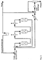
- Reference is made to Fig. 1. This is a calculation example of the process according to the invention.
- The synthesis gas module as defined above is 2.05. The synthesis pressure is 107 kg/cm2.
- Fresh (make-up) synthesis gas is mixed with recycle synthesis gas and preheated to 225°C. A reactor by-pass stream (15%) is split from the reactor feed stream, before it is introduced to a cooled reactor (R1) loaded with a catalyst active in methanol synthesis. The cooled reactor is a boiling water reactor type with catalyst inside tubes cooled on the shell side by boiling water, which serves to remove reaction heat. The pressure of the boiling water and thereby also its temperature (265°C) controls the temperature of the cooled reactor effluent (274°C). The by-pass stream is added to the cooled reactor effluent and passed to an adiabatic reactor (R2) containing a bed of combined catalyst and a bed of dehydration catalyst. The amount of bypass determines the temperature of the admixture (266°C) and the temperature rise (21°C) in the subsequent adiabatic bed of combined catalyst, thereby controlling the inlet temperature (287°C) to the dehydration catalyst bed. The DME reactor effluent is cooled by heat exchange with the synthesis gas admixture and further by one or more coolers, eventually being cooled by typically cooling water to 35°C.
- Product is separated from the unconverted synthesis gas, which is split into a purge gas stream and a recycle synthesis gas stream, which after repressurization in a recycle compressor is mixed with the fresh synthesis gas (as mentioned earlier) for further conversion.
- Results from the process calculation are presented in Tables 1 and 2 below.
- Reference is made to Fig. 2. This is not a calculation example of the process of the invention, but a comparative calculation example demonstrating a conventional process for direct DME synthesis.
- The synthesis gas composition is identical to Example 1. The synthesis pressure is reduced to 80 kg/cm2, as the water partial pressure formed under the combined synthesis would otherwise drastically deactivate the methanol function of the combined catalyst. This is also the reason for having to change the main conversion reactor type from a cooled to an adiabatic type, as the recycle rate in a cooled reactor layout is substantially lower.
- All reactors (R1, R2, and R3) are loaded with combined catalyst as described above.
- Fresh (make-up) synthesis gas is mixed with recycle synthesis gas and preheated to 231°C and led to the first adiabatic conversion step (R1). The first reactor effluent reaches a temperature of 305°C is then cooled to 245°C in a reactor intercooler and led to the next adiabatic conversion step (R2). The effluent from the second reactor passes another intercooler and another conversion step (R3). It is thereafter cooled by heat exchange with the cold synthesis gas admixture and one or more other heat exchangers. It is then cooled further in a so-called cold exchanger followed by cooling in a chiller to 0°C and led to a separator, where unconverted synthesis gas is separated from synthesis products. The chilled gas is heated up in the cold exchanger, a purge gas stream is split from the synthesis gas before it is repressurized in a recycle compressor and mixed with fresh synthesis gas.
- Reference is made to Fig. 1. In this calculation example, the catalyst loaded into the second reactor (R2) is without the activity in methanol synthesis from synthesis gas as in Example 1. The bypass split around the cooled reactor (R1) is 0% and this process does not represent a process according to the invention .
- The synthesis gas composition and pressure are identical to that of Example 1.
- Fresh (make-up) synthesis gas is mixed with recycle synthesis gas and preheated to 225°C. The gas admixture is introduced to a cooled reactor (R1) loaded with a catalyst active in methanol synthesis. The cooled reactor is similar to that of Example 1 with boiling water at 265°C. The reactor effluent (273°C) rich in methanol is passed on to a reactor (R2) loaded with dehydration catalyst, where methanol is converted to DME and water. The DME reactor effluent (305°C) is cooled by heat exchange with the synthesis gas admixture and further by one or more coolers, eventually being cooled by typically cooling water to 35°C. As in Example 1, product is separated from the unconverted synthesis gas, which is split into a purge gas stream and a recycle stream, which after repressurisation in a recycle compressor is mixed with the fresh synthesis gas for further conversion.
- Results from the process calculation are presented in Tables 1 and 2 below.
Compositions from the synthesis comparison. Flow sheet Positions Make-up Synthesis gas Methanol Function Effluent Condensate Example No. 1 2 3 1 2 3 1 2 3 Components (mole%): H2 66.24 50.30 58.18 51.78 0.55 0.47 0.60 CO 24.65 7.08 4.66 5.78 0.15 0.10 0.10 CO2 5.15 6.79 7.40 7.66 2.20 4.41 2.90 Inerts 3.77 18.02 18.78 17.16 0.74 0.61 0.59 MeOH 8.38 2.13 8.04 29.60 28.88 30.15 DME 8.04 6.03 7.71 24.38 26.87 24.78 H2O 0.18 1.39 2.82 1.87 42.38 38.66 40.88 - The methanol function effluent is the composition of the synthesis gas in the position, where it leaves the last bed which contains catalyst active in methanol synthesis from synthesis gas, i.e. in Example 1 the first bed of the second reactor R2, in Example 2 the third reactor R3, and in Example 3 the first reactor R1. This composition has been presented as to demonstrate the maximum water concentration the methanol function catalyst is subjected to in the respective synthesis examples.
Feed / Production Index Recycle / Make-up Synthesis gas Ratio Total molar Product Ratio (DME/MeOH) Catalyst Volume Index Ex. 1 100/100 2.58 1.02 100 Ex. 2 100/100 3.60 1.02 121 Ex. 3 100/100 2.65 1.02 110 - As is shown in the key figures in the above Tables 1 and 2, a product mixture equally rich in DME is obtained in the calculation Examples 1 and 3 at a lower recycle rate with a lower amount of catalyst. Bearing in mind that the DME/methanol product is recovered at a low cost in Examples 1 and 3, and that the investment of equipment is reduced compared to Example 2, it is demonstrated that substantial improvements are gained when applying the process according to the invention compared to the conventional combined direct synthesis process.
Claims (4)
- A process for the production of a DME/methanol product mixture rich in DME from a make-up stream of an essentially stoichiometrically balanced synthesis gas of H2/CO/CO2, consisting of the following process steps:(a) passing a stream of synthesis gas through a cooled reactor containing a catalyst active in methanol formation from synthesis gas, forming an effluent stream enriched in methanol;(b) contacting the methanol enriched effluent stream from (a) with a catalyst active in methanol formation from synthesis gas and/or a combined catalyst active in methanol formation and dehydration;(c) bringing the effluent from step (b) in contact with a catalyst active in dehydration of methanol, forming a synthesis gas stream further enriched in DME;(d) withdrawing the DME enriched synthesis gas stream from step (c) and separating the stream into a DME/methanol product mixture rich in DME and a partly converted synthesis gas stream; and(e) recycling a predetermined amount of the partly converted synthesis gas stream to the make-up stream of synthesis gas, forming the synthesis gas stream of step (a); and characterised by(f) splitting a bypass stream from the synthesis gas stream prior to passing it through the cooled reactor in step (a) and combining the bypass stream with the synthesis gas enriched in methanol prior to contacting it with the catalyst in step (b).
- A process according to claim 1, wherein the catalyst in process step (b) is arranged in one or more beds, whereof at least one bed of catalyst is further active in dehydration of methanol.
- A process according to claim 1, wherein the catalysts in process steps (b) and (c) are contained in a common reactor shell.
- A process according to claims 1 and 2, wherein the process steps (b) and (c) are performed under adiabatic conditions.
Applications Claiming Priority (2)
| Application Number | Priority Date | Filing Date | Title |
|---|---|---|---|
| DK199900132A DK173614B1 (en) | 1999-02-02 | 1999-02-02 | Process for preparing methanol / dimethyl ether mixture from synthesis gas |
| DK13299 | 1999-02-02 |
Publications (2)
| Publication Number | Publication Date |
|---|---|
| EP1026141A1 EP1026141A1 (en) | 2000-08-09 |
| EP1026141B1 true EP1026141B1 (en) | 2003-06-18 |
Family
ID=8090111
Family Applications (1)
| Application Number | Title | Priority Date | Filing Date |
|---|---|---|---|
| EP00100167A Expired - Lifetime EP1026141B1 (en) | 1999-02-02 | 2000-01-11 | Process for the synthesis of a methanol/dimethyl ether mixture from synthesis gas |
Country Status (14)
| Country | Link |
|---|---|
| US (1) | US6191175B1 (en) |
| EP (1) | EP1026141B1 (en) |
| JP (1) | JP4545855B2 (en) |
| KR (1) | KR100392930B1 (en) |
| CN (1) | CN100349839C (en) |
| AT (1) | ATE243180T1 (en) |
| AU (1) | AU766364B2 (en) |
| BR (1) | BR0000228A (en) |
| CA (1) | CA2297548A1 (en) |
| DE (1) | DE60003346T2 (en) |
| DK (1) | DK173614B1 (en) |
| ES (1) | ES2200734T3 (en) |
| NO (1) | NO315155B1 (en) |
| ZA (1) | ZA200000433B (en) |
Families Citing this family (18)
| Publication number | Priority date | Publication date | Assignee | Title |
|---|---|---|---|---|
| US6608114B1 (en) * | 2002-03-13 | 2003-08-19 | Air Products And Chemicals, Inc. | Process to produce DME |
| CN1938400B (en) * | 2004-02-05 | 2012-01-04 | 沙索技术有限公司 | Hydrocarbon synthesis |
| WO2007014487A1 (en) * | 2005-08-01 | 2007-02-08 | Dalian Institute Of Chemical Physics, Chinese Academy Of Sciences | An integrated process for the co-production of methanol and demethyl ether from syngas containing nitrogen |
| CN101454263B (en) * | 2006-05-30 | 2012-11-28 | 星化学技术公司 | Methanol production process and system |
| US20080260631A1 (en) * | 2007-04-18 | 2008-10-23 | H2Gen Innovations, Inc. | Hydrogen production process |
| DE102007040707B4 (en) * | 2007-08-29 | 2012-05-16 | Lurgi Gmbh | Process and plant for the production of methanol |
| WO2010069549A1 (en) | 2008-12-17 | 2010-06-24 | Saudi Basic Industries Corporation | Process for increasing the carbon monoxide content of a syngas mixture |
| JP5311345B2 (en) * | 2009-03-12 | 2013-10-09 | Jx日鉱日石エネルギー株式会社 | Method for producing oxygen-containing compound |
| DE102009046790B9 (en) | 2009-11-17 | 2013-05-08 | Chemieanlagenbau Chemnitz Gmbh | Process for the production of hydrocarbons, in particular gasoline, from synthesis gas |
| EP2450100A1 (en) * | 2010-10-22 | 2012-05-09 | Methanol Casale S.A. | Process and plant for the production of methanol with isothermal catalytic beds |
| US9393555B2 (en) | 2012-02-15 | 2016-07-19 | Basf Se | Catalytically active body for the synthesis of dimethyl ether from synthesis gas |
| US9610568B2 (en) | 2012-02-15 | 2017-04-04 | Basf Se | Catalytically active body for the synthesis of dimethyl ether from synthesis gas |
| KR20150008884A (en) | 2012-04-24 | 2015-01-23 | 바스프 에스이 | Catalytically active body for the synthesis of dimethyl ether from synthesis gas |
| EP2898943B1 (en) | 2014-01-28 | 2016-11-16 | Linde Aktiengesellschaft | Process and apparatus for the obtention of dimethylether from syngas |
| EP2913320A1 (en) * | 2014-02-27 | 2015-09-02 | Linde Aktiengesellschaft | Method and assembly for the production of oxygenates with continuous heat exchange between the input flow and raw product flow |
| US9981896B2 (en) | 2016-07-01 | 2018-05-29 | Res Usa, Llc | Conversion of methane to dimethyl ether |
| US9938217B2 (en) | 2016-07-01 | 2018-04-10 | Res Usa, Llc | Fluidized bed membrane reactor |
| WO2018004993A1 (en) | 2016-07-01 | 2018-01-04 | Res Usa, Llc | Reduction of greenhouse gas emission |
Family Cites Families (18)
| Publication number | Priority date | Publication date | Assignee | Title |
|---|---|---|---|---|
| DE291937C (en) | ||||
| IT972655B (en) | 1972-12-20 | 1974-05-31 | Snam Progetti | PROCEDURE FOR THE PRODUCTION OF DIMETHYL ETHER |
| US4098809A (en) | 1972-12-20 | 1978-07-04 | Snamprogetti S.P.A. | Process for the production of dimethyl ether |
| IT1065295B (en) | 1976-12-23 | 1985-02-25 | Snam Progetti | PROCESS FOR THE PRODUCTION OF DIMETHYL ETHER AND CATALYST USED IN THIS PROCESS |
| NZ199035A (en) | 1981-02-20 | 1984-09-28 | Mobil Oil Corp | Catalyst of co-precipitated cu,zu and a1 components:conversion of syngas into dimethyl ether |
| GB2097383B (en) | 1981-04-28 | 1985-06-12 | Great Lakes Chemical Corp | Perbromination of phenol and diphenyl ether |
| DE3118620A1 (en) | 1981-05-11 | 1982-11-25 | Mobil Oil Corp., 10017 New York, N.Y. | Process for converting synthesis gas into dimethyl ether |
| IT1137176B (en) | 1981-06-02 | 1986-09-03 | Anic Spa | PROCESS FOR THE PRODUCTION OF DIMETHYLETER |
| US4375424A (en) | 1981-10-21 | 1983-03-01 | Shell Oil Company | Catalyst for the preparation of dimethyl ether |
| US4417000A (en) | 1982-08-04 | 1983-11-22 | Shell Oil Company | Dimethyl ether process |
| US4590176A (en) * | 1984-06-05 | 1986-05-20 | Shell Oil Company | Catalyst for dimethyl ether synthesis and a process for its preparation |
| DE3540457A1 (en) * | 1985-11-14 | 1987-05-21 | Linde Ag | Process and reactor for methanol synthesis |
| US4857667A (en) * | 1987-04-29 | 1989-08-15 | Mobil Oil Corporation | System for conversion of crude oxygenate to gasoline with feedstock extraction |
| EP0340324B1 (en) | 1988-05-04 | 1992-12-16 | RWE-DEA Aktiengesellschaft für Mineraloel und Chemie | Process for the preparation of pure dimethyl ether |
| DE3817816A1 (en) * | 1988-05-26 | 1989-11-30 | Union Rheinische Braunkohlen | METHOD FOR PRODUCING DIMETHYL ETHER |
| AU5902490A (en) | 1989-07-18 | 1991-08-01 | Air Products And Chemicals Inc. | One-step liquid phase process for dimethyl ether synthesis |
| US5254596A (en) | 1992-09-15 | 1993-10-19 | Eastman Kodak Company | Process for the manufacture of methanol and dimethyl ether |
| DK171707B1 (en) * | 1995-02-03 | 1997-04-01 | Topsoe Haldor As | Process for producing fuel grade dimethyl ether |
-
1999
- 1999-02-02 DK DK199900132A patent/DK173614B1/en not_active IP Right Cessation
- 1999-11-09 JP JP31873999A patent/JP4545855B2/en not_active Expired - Lifetime
-
2000
- 2000-01-11 AT AT00100167T patent/ATE243180T1/en not_active IP Right Cessation
- 2000-01-11 DE DE60003346T patent/DE60003346T2/en not_active Expired - Lifetime
- 2000-01-11 EP EP00100167A patent/EP1026141B1/en not_active Expired - Lifetime
- 2000-01-11 ES ES00100167T patent/ES2200734T3/en not_active Expired - Lifetime
- 2000-01-25 US US09/491,208 patent/US6191175B1/en not_active Expired - Lifetime
- 2000-01-31 KR KR10-2000-0004693A patent/KR100392930B1/en not_active IP Right Cessation
- 2000-01-31 BR BR0000228-3A patent/BR0000228A/en not_active Application Discontinuation
- 2000-02-01 CA CA002297548A patent/CA2297548A1/en not_active Abandoned
- 2000-02-01 NO NO20000511A patent/NO315155B1/en not_active IP Right Cessation
- 2000-02-01 ZA ZA200000433A patent/ZA200000433B/en unknown
- 2000-02-01 AU AU14839/00A patent/AU766364B2/en not_active Expired
- 2000-02-02 CN CNB001018833A patent/CN100349839C/en not_active Expired - Lifetime
Also Published As
| Publication number | Publication date |
|---|---|
| JP2000226348A (en) | 2000-08-15 |
| DE60003346T2 (en) | 2003-12-04 |
| AU1483900A (en) | 2000-08-31 |
| JP4545855B2 (en) | 2010-09-15 |
| AU766364B2 (en) | 2003-10-16 |
| KR20000076574A (en) | 2000-12-26 |
| NO20000511D0 (en) | 2000-02-01 |
| US6191175B1 (en) | 2001-02-20 |
| CN1270157A (en) | 2000-10-18 |
| DE60003346D1 (en) | 2003-07-24 |
| BR0000228A (en) | 2001-08-21 |
| CA2297548A1 (en) | 2000-08-02 |
| KR100392930B1 (en) | 2003-07-28 |
| CN100349839C (en) | 2007-11-21 |
| NO20000511L (en) | 2000-08-03 |
| EP1026141A1 (en) | 2000-08-09 |
| ES2200734T3 (en) | 2004-03-16 |
| ZA200000433B (en) | 2000-09-06 |
| DK199900132A (en) | 2000-08-03 |
| ATE243180T1 (en) | 2003-07-15 |
| NO315155B1 (en) | 2003-07-21 |
| DK173614B1 (en) | 2001-04-30 |
Similar Documents
| Publication | Publication Date | Title |
|---|---|---|
| EP1026141B1 (en) | Process for the synthesis of a methanol/dimethyl ether mixture from synthesis gas | |
| AU749586B2 (en) | Methanol synthesis | |
| US7786180B2 (en) | Methanol synthesis | |
| US6214314B1 (en) | Process for the preparation methanol and hydrogen | |
| EP3983365B1 (en) | Process for synthesising methanol | |
| AU2004205368B2 (en) | Methanol synthesis | |
| CN108101742B (en) | Method for reforming methanol process | |
| EP3793970B1 (en) | Process for synthesising methanol | |
| US5173513A (en) | Methanol synthesis | |
| CA2985284A1 (en) | Use of syngas comprising carbon monoxide and water in the synthesis of methanol | |
| CA1231977A (en) | Production of carbon compounds from a carbon oxide/ hydrogen synthesis gas | |
| US4692322A (en) | Process for producing a product gas containing carbon oxides and hydrogen from methanol | |
| GB2606855A (en) | Process for synthesising methanol |
Legal Events
| Date | Code | Title | Description |
|---|---|---|---|
| PUAI | Public reference made under article 153(3) epc to a published international application that has entered the european phase |
Free format text: ORIGINAL CODE: 0009012 |
|
| AK | Designated contracting states |
Kind code of ref document: A1 Designated state(s): AT BE CH CY DE DK ES FI FR GB GR IE IT LI LU MC NL PT SE |
|
| AX | Request for extension of the european patent |
Free format text: AL;LT;LV;MK;RO;SI |
|
| 17P | Request for examination filed |
Effective date: 20010209 |
|
| AKX | Designation fees paid |
Free format text: AT BE CH CY DE DK ES FI FR GB GR IE IT LI LU MC NL PT SE |
|
| 17Q | First examination report despatched |
Effective date: 20010425 |
|
| GRAH | Despatch of communication of intention to grant a patent |
Free format text: ORIGINAL CODE: EPIDOS IGRA |
|
| GRAH | Despatch of communication of intention to grant a patent |
Free format text: ORIGINAL CODE: EPIDOS IGRA |
|
| GRAA | (expected) grant |
Free format text: ORIGINAL CODE: 0009210 |
|
| AK | Designated contracting states |
Designated state(s): AT BE CH CY DE DK ES FI FR GB GR IE IT LI LU MC NL PT SE |
|
| PG25 | Lapsed in a contracting state [announced via postgrant information from national office to epo] |
Ref country code: LI Free format text: LAPSE BECAUSE OF FAILURE TO SUBMIT A TRANSLATION OF THE DESCRIPTION OR TO PAY THE FEE WITHIN THE PRESCRIBED TIME-LIMIT Effective date: 20030618 Ref country code: CH Free format text: LAPSE BECAUSE OF FAILURE TO SUBMIT A TRANSLATION OF THE DESCRIPTION OR TO PAY THE FEE WITHIN THE PRESCRIBED TIME-LIMIT Effective date: 20030618 Ref country code: AT Free format text: LAPSE BECAUSE OF FAILURE TO SUBMIT A TRANSLATION OF THE DESCRIPTION OR TO PAY THE FEE WITHIN THE PRESCRIBED TIME-LIMIT Effective date: 20030618 Ref country code: CY Free format text: LAPSE BECAUSE OF FAILURE TO SUBMIT A TRANSLATION OF THE DESCRIPTION OR TO PAY THE FEE WITHIN THE PRESCRIBED TIME-LIMIT Effective date: 20030618 |
|
| REG | Reference to a national code |
Ref country code: GB Ref legal event code: FG4D |
|
| REG | Reference to a national code |
Ref country code: CH Ref legal event code: EP |
|
| REG | Reference to a national code |
Ref country code: IE Ref legal event code: FG4D |
|
| REF | Corresponds to: |
Ref document number: 60003346 Country of ref document: DE Date of ref document: 20030724 Kind code of ref document: P |
|
| PG25 | Lapsed in a contracting state [announced via postgrant information from national office to epo] |
Ref country code: PT Free format text: LAPSE BECAUSE OF FAILURE TO SUBMIT A TRANSLATION OF THE DESCRIPTION OR TO PAY THE FEE WITHIN THE PRESCRIBED TIME-LIMIT Effective date: 20030918 Ref country code: DK Free format text: LAPSE BECAUSE OF FAILURE TO SUBMIT A TRANSLATION OF THE DESCRIPTION OR TO PAY THE FEE WITHIN THE PRESCRIBED TIME-LIMIT Effective date: 20030918 Ref country code: GR Free format text: LAPSE BECAUSE OF FAILURE TO SUBMIT A TRANSLATION OF THE DESCRIPTION OR TO PAY THE FEE WITHIN THE PRESCRIBED TIME-LIMIT Effective date: 20030918 |
|
| REG | Reference to a national code |
Ref country code: SE Ref legal event code: TRGR |
|
| REG | Reference to a national code |
Ref country code: CH Ref legal event code: PL |
|
| PG25 | Lapsed in a contracting state [announced via postgrant information from national office to epo] |
Ref country code: LU Free format text: LAPSE BECAUSE OF NON-PAYMENT OF DUE FEES Effective date: 20040111 |
|
| PG25 | Lapsed in a contracting state [announced via postgrant information from national office to epo] |
Ref country code: SE Free format text: LAPSE BECAUSE OF NON-PAYMENT OF DUE FEES Effective date: 20040112 Ref country code: IE Free format text: LAPSE BECAUSE OF NON-PAYMENT OF DUE FEES Effective date: 20040112 |
|
| PG25 | Lapsed in a contracting state [announced via postgrant information from national office to epo] |
Ref country code: MC Free format text: LAPSE BECAUSE OF NON-PAYMENT OF DUE FEES Effective date: 20040131 |
|
| REG | Reference to a national code |
Ref country code: ES Ref legal event code: FG2A Ref document number: 2200734 Country of ref document: ES Kind code of ref document: T3 |
|
| ET | Fr: translation filed | ||
| PLBE | No opposition filed within time limit |
Free format text: ORIGINAL CODE: 0009261 |
|
| STAA | Information on the status of an ep patent application or granted ep patent |
Free format text: STATUS: NO OPPOSITION FILED WITHIN TIME LIMIT |
|
| 26N | No opposition filed |
Effective date: 20040319 |
|
| EUG | Se: european patent has lapsed | ||
| REG | Reference to a national code |
Ref country code: IE Ref legal event code: MM4A |
|
| REG | Reference to a national code |
Ref country code: FR Ref legal event code: PLFP Year of fee payment: 17 |
|
| REG | Reference to a national code |
Ref country code: FR Ref legal event code: PLFP Year of fee payment: 18 |
|
| REG | Reference to a national code |
Ref country code: FR Ref legal event code: PLFP Year of fee payment: 19 |
|
| PGFP | Annual fee paid to national office [announced via postgrant information from national office to epo] |
Ref country code: FI Payment date: 20190122 Year of fee payment: 20 Ref country code: GB Payment date: 20190130 Year of fee payment: 20 Ref country code: NL Payment date: 20190125 Year of fee payment: 20 Ref country code: ES Payment date: 20190225 Year of fee payment: 20 Ref country code: IT Payment date: 20190125 Year of fee payment: 20 Ref country code: FR Payment date: 20190128 Year of fee payment: 20 |
|
| PGFP | Annual fee paid to national office [announced via postgrant information from national office to epo] |
Ref country code: BE Payment date: 20190131 Year of fee payment: 20 |
|
| PGFP | Annual fee paid to national office [announced via postgrant information from national office to epo] |
Ref country code: DE Payment date: 20190401 Year of fee payment: 20 |
|
| REG | Reference to a national code |
Ref country code: DE Ref legal event code: R071 Ref document number: 60003346 Country of ref document: DE |
|
| REG | Reference to a national code |
Ref country code: NL Ref legal event code: MK Effective date: 20200110 |
|
| REG | Reference to a national code |
Ref country code: GB Ref legal event code: PE20 Expiry date: 20200110 |
|
| REG | Reference to a national code |
Ref country code: FI Ref legal event code: MAE |
|
| REG | Reference to a national code |
Ref country code: BE Ref legal event code: MK Effective date: 20200111 |
|
| PG25 | Lapsed in a contracting state [announced via postgrant information from national office to epo] |
Ref country code: GB Free format text: LAPSE BECAUSE OF EXPIRATION OF PROTECTION Effective date: 20200110 |
|
| REG | Reference to a national code |
Ref country code: ES Ref legal event code: FD2A Effective date: 20200721 |
|
| PG25 | Lapsed in a contracting state [announced via postgrant information from national office to epo] |
Ref country code: ES Free format text: LAPSE BECAUSE OF EXPIRATION OF PROTECTION Effective date: 20200112 |