EP1025667B1 - Procede et systeme d'evaluation, a la reception, de la qualite d'un signal numerique, tel qu'un signal audio/video numerique - Google Patents
Procede et systeme d'evaluation, a la reception, de la qualite d'un signal numerique, tel qu'un signal audio/video numerique Download PDFInfo
- Publication number
- EP1025667B1 EP1025667B1 EP98947644A EP98947644A EP1025667B1 EP 1025667 B1 EP1025667 B1 EP 1025667B1 EP 98947644 A EP98947644 A EP 98947644A EP 98947644 A EP98947644 A EP 98947644A EP 1025667 B1 EP1025667 B1 EP 1025667B1
- Authority
- EP
- European Patent Office
- Prior art keywords
- signal
- broadcast
- reference signal
- digital
- digital signal
- Prior art date
- Legal status (The legal status is an assumption and is not a legal conclusion. Google has not performed a legal analysis and makes no representation as to the accuracy of the status listed.)
- Expired - Lifetime
Links
- 238000000034 method Methods 0.000 title claims abstract description 71
- 230000005236 sound signal Effects 0.000 claims description 65
- 230000003595 spectral effect Effects 0.000 claims description 57
- 230000005540 biological transmission Effects 0.000 claims description 53
- 238000011156 evaluation Methods 0.000 claims description 19
- 238000005070 sampling Methods 0.000 claims description 8
- 238000001228 spectrum Methods 0.000 claims description 8
- MJEMIOXXNCZZFK-UHFFFAOYSA-N ethylone Chemical compound CCNC(C)C(=O)C1=CC=C2OCOC2=C1 MJEMIOXXNCZZFK-UHFFFAOYSA-N 0.000 claims description 7
- 238000011144 upstream manufacturing Methods 0.000 claims description 3
- 108010076504 Protein Sorting Signals Proteins 0.000 claims description 2
- 238000005314 correlation function Methods 0.000 claims 2
- 230000001360 synchronised effect Effects 0.000 abstract description 10
- 238000004364 calculation method Methods 0.000 description 23
- 238000009792 diffusion process Methods 0.000 description 9
- 230000006870 function Effects 0.000 description 6
- 238000012360 testing method Methods 0.000 description 4
- 238000003780 insertion Methods 0.000 description 3
- 230000037431 insertion Effects 0.000 description 3
- 238000005259 measurement Methods 0.000 description 3
- 238000013441 quality evaluation Methods 0.000 description 3
- 230000002123 temporal effect Effects 0.000 description 3
- 230000006835 compression Effects 0.000 description 2
- 238000007906 compression Methods 0.000 description 2
- 238000012854 evaluation process Methods 0.000 description 2
- 238000001303 quality assessment method Methods 0.000 description 2
- 230000000717 retained effect Effects 0.000 description 2
- 230000009466 transformation Effects 0.000 description 2
- 238000007476 Maximum Likelihood Methods 0.000 description 1
- 241000135309 Processus Species 0.000 description 1
- 241001080024 Telles Species 0.000 description 1
- 239000002131 composite material Substances 0.000 description 1
- 238000000354 decomposition reaction Methods 0.000 description 1
- 230000006837 decompression Effects 0.000 description 1
- 230000007423 decrease Effects 0.000 description 1
- 238000010586 diagram Methods 0.000 description 1
- 238000000605 extraction Methods 0.000 description 1
- 230000000873 masking effect Effects 0.000 description 1
- 230000008447 perception Effects 0.000 description 1
- 230000000737 periodic effect Effects 0.000 description 1
- 238000012545 processing Methods 0.000 description 1
- 238000004088 simulation Methods 0.000 description 1
- 238000010183 spectrum analysis Methods 0.000 description 1
- 238000011282 treatment Methods 0.000 description 1
Images



Classifications
-
- H—ELECTRICITY
- H04—ELECTRIC COMMUNICATION TECHNIQUE
- H04H—BROADCAST COMMUNICATION
- H04H20/00—Arrangements for broadcast or for distribution combined with broadcast
- H04H20/28—Arrangements for simultaneous broadcast of plural pieces of information
-
- H—ELECTRICITY
- H04—ELECTRIC COMMUNICATION TECHNIQUE
- H04L—TRANSMISSION OF DIGITAL INFORMATION, e.g. TELEGRAPHIC COMMUNICATION
- H04L1/00—Arrangements for detecting or preventing errors in the information received
- H04L1/20—Arrangements for detecting or preventing errors in the information received using signal quality detector
Definitions
- Transmission techniques more and more oriented towards the transmission of digital signals, have purpose of which is to reduce transmission rates, by encoding and compression-decoding decompression, so as not to overload the transmission networks and thus allow optimized use of these, while retaining however a high quality of transmission.
- the notion of quality of the transmitted signal is analyzed essentially in a subjective quality of the latter.
- the subjective quality of this coded-decoded sound signal is an estimated quality using subjective tests. These subjective tests consist essentially in attributing a note of value to this coded-decoded sound signal by doing estimate its quality by a set of auditors.
- the objective perceptual measurement processes all operate according to an identical principle comparing the coded-decoded sound signal to the original signal.
- the original signal is constituted by the digital audio signal before coding and compression, also called signal of reference.
- the implementation of the aforementioned processes requires therefore to have a reference signal, which must to be finely synchronized with the digital audio signal to test.
- Such constraints can easily be satisfied in simulation, for example, to evaluate software a coding process, or when broadcast transmission of a digital audio signal or audio / digital video, during the transmission stage of this last, in order to evaluate the objective quality of a signal transmitted code.
- the present invention aims to remedy the aforementioned drawback, in order to allow the application, to receiving, direct evaluation process of the transmission quality of a broadcast digital signal, and, in the more specific case of a digital audio signal or audio / digital video, objective perceptual measurements.
- This object is achieved by the implementation of a method for evaluating the quality of a digital signal according to claim 1.
- the present invention finds application to the transmission of digital signals over the air or satellite, especially in the case of audio signals and / or audio / digital video, such as television or radio signals.
- the process, object of the present invention is likely to be applied to any kind of digital signal but in particular to audio / digital video signals such as television signals for example, featuring classical audio component, which, in the context of the description of the process, object of the present invention, is deemed to be a digital audio signal. he is also likely to be applied to the video part of digital video signals, under conditions that will be explained later in the description.
- the method, object of the present invention is intended to be implemented on any broadcast network of such a signal, this digital signal being accordingly broadcast from an original signal conveying the information transmitted.
- the transmission or broadcasting network of this digital signal is thus deemed to be constituted by all radio or satellite network allowing the broadcasting of this digital signal from a broadcast headend as well as receiving this digital signal from at minus a specific receiving point. Characteristics relating to the mode of transmission over the air and / or satellite of this type of network are known to the state of the technique and, for this reason, will not be described in detail.
- an origin signal which may be by a baseband signal of the signal to be transmitted as well than a digital signal per se, which is digitized in a conventional way, in order to allow the transmission by broadcasting it over the air or satellite.
- object of the present invention is provided in transmission head of the network, in one step 1000, not only of the original signal, noted n / a, but also of the signal digital proper, noted for this reason sn.
- the process, object of the present invention consists, on transmission, in a step 1001, to generate a reference signal, denoted sref, representative of the original signal.
- a reference signal denoted sref
- the signal reference reproduces, at least partially, this signal origin or certain specific characteristics of this one.
- the signal reference may consist of certain samples of the digital signal sn, these samples of the digital signal sn being taken on a slice or window of definite duration digital signal and inserted at specific places in the digital train constituting the digital signal to be broadcast.
- the reference signal can be inserted at as a non-limitative example, in the MPEG stream by use of the private auxiliary data bits provided for to transmit data.
- All of these signals are thus transmitted by diffusion, the method which is the subject of the present invention furthermore, at the reception, at the point of reception of the aforementioned broadcasting network, to perform the receiving the digital signal and the reference signal broadcast.
- the broadcasted digital audio signal received snr and the signal broadcast reference received srefr available at step 2000 mentioned above are not synchronized sufficiently precise to allow the direct implementation of a process of assessing the transmission quality of the digital signal mentioned above.
- the method, object of this invention furthermore, on receipt, as well as represented in Figure 1, in a step 2001, to synchronize the broadcast digital signal received snr and the reference signal broadcast received srefr, and then, in a step 2002, to calculate a distance value, this distance value being defined as the difference of identity separating the broadcast digital signal received snr from the reference signal broadcast received srefr.
- the distance value is denoted D on the figure 1.
- the step 2002 of calculating the distance value D is then followed by a step 2003 of attributing, on the criterion of the value of the above-mentioned distance D, a value of quality Q according to a predetermined criterion.
- a reference signal may consist of generating an arbitrary digital signal sequence.
- This arbitrary sequence may preferably be constitutive of the original signal.
- the 2002 step of distance value calculation that is to say of the difference identity separating the broadcast digital signal received from the broadcast reference signal received, is then conducted between this received broadcast digital signal and the arbitrary sequence.
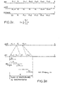
- FIG. 2a shows the implementation by sampling the original signal for example, in one step 1001a making it possible to generate the arbitrary sequence noted SA in the above figure.
- the step of generating the reference signal 1001 may consist, as well as represented in FIG. 2b, sampling the original signal or, preferably, the digital signal sn in a step 1001a 'on windows or slots of arbitrary determined duration, each window being denoted by F i in FIG. 2b supra.
- the successive windows are noted F i-1 , F i , F i + 1 in Figure 2b above.
- each window F iM , F i , F i + M is inserted in the digital train of the digital signal sn.
- each window can be inserted into the MPEG stream by using the private auxiliary data bits provided for transmitting data.
- the digital broadcast signal received snr and the received broadcast reference signal srefr being deemed to be synchronized, it is shown, as shown in FIG. 2c, on the one hand, of the sequence of windows F i-1 , F i , F i + 1 ... successive, constituting the digital broadcast signal received snr and the received broadcast reference signal srefr.
- the step 2002 of calculating the distance value D may then consist in calculating the elementary distance d i between time slots of the received digital broadcast signal of corresponding time slots of the received broadcast reference signal.
- These elementary distances are denoted d i in FIG. 2c, each calculated elementary distance comprising the same index as the corresponding window F i of the digital broadcast signal received snr.
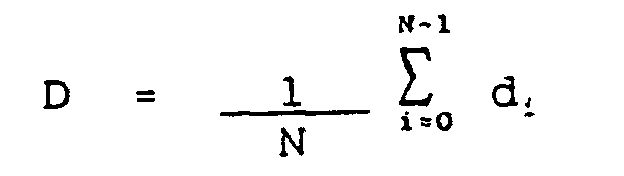
- a time average of the elementary distances d i of the set of time slots is calculated in order to obtain the distance value D itself.
- N successive slices such as the slices F i-1 to F i + 5, for example, as represented in FIG. 2c, the actual distance between the two signals is then given by:
- the method, object of the present invention in order to ensure the fine synchronization of the aforementioned signals, consists in defining, on the digital broadcast signal received snr, a synchronization probability range P of this signal. vis-à-vis the reference signal srefr, in particular a value or window, time slice, reference R j given.
- the index j indicates any value of this index corresponding, for example, to one of the index values i-4, i or i + 4 of FIG. 2c.
- FIG. 2d shows, by way of non-limiting example, four time windows F i-2 , F i-1 , F i , F i + 1 deemed to constitute the range P. It is obvious that the number of successive windows F i constituting the aforementioned range P can be multiplied, only higher computing power being necessary for a higher number of successive windows constituting the P range previously mentioned. For example, it will be possible to retain a number of successive windows comprised between 50 and 100.
- the latter furthermore consists, then, in calculating a distance between each successive time slot shifted T k of the digital signal received snr and the reference window R j .
- the corresponding distances are denoted dT k for any time slot T k of the synchronicity likelihood range P cited above.
- the set of distance values between each successive offset time slot and the reference signal R j is then subjected to a sorting process, so as to determine the minimum distance value on the set considered. This minimum value is noted min dT k .
- the reference signal consisting for example of a reference window R j and the time slice considered T k in the case of the implementation of the synchronization process or, respectively, any slice or time window F i and the synchronized reference time value or slice R i , in the case of FIG. 2c
- this method of calculating the intercorrelation function is quite conventional. Indeed, both the window F i received digital signal received snr and the received broadcast reference signal sref in its reference window R i , consist of the same number of samples and the intercorrelation function therefore corresponds to a definition quite classic. It is the same for the time slots T k and the time slot or reference time window R j for the implementation of the synchronization process shown in Figure 2d.
- the calculation process consists of at least one time slice of the received broadcast reference signal srefr and one time slice of the received broadcast digital audio signal snr to calculate the power spectral density of the received broadcast reference signal.
- srefr in one step, 2002a 1 and the power spectral density of the digital broadcast signal received snr in a step 2002a 2 to generate a power spectral density signal of the received broadcast reference signal and a signal power spectral density signal.
- distributed digital audio received each noted for this reason dsrefr and dsnr respectively.
- the calculation of the power spectral density, both of the digital audio signal broadcast received snr only received broadcast reference signal srefr, can advantageously be performed in barks.
- the method, object of the present invention consists in applying to each signal of power spectral density dsrefr and dsnr a spread spectrum spectrum processing, to generate a signal of spectral density of the power of the spread received spread reference signal, respectively a power spectral density signal of the scattered received distributed digital audio signal, these signals being denoted respectively as dsrefre and dsnre.
- a comparison at step 2002c is made between the spectral power density signal of the signal of scatter reference spread received dsrefre and density signal power spectral of the received broadcast digital audio signal spread out dsnre to generate the value of distance D obtained in step 2002d shown in Figure 2e.
- the distance calculation can then be performed between the psychoacoustic representations of the two signals. This distance can then be related to the quality of the signal to evaluate. The lower the distance, the more the signal to evaluate is close to the original signal, and better is the broadcast quality of the latter.
- this slice is represented by 32 kbits of data.
- the representation spectral in the barks field of this time slice can instead be represented by 768 bits, about 42 times less. Indeed, for a spectral resolution of 1 bark and an analysis covering a band from 1 to 24 barks over a frequency range from 0 to 15 500 Hz, the spectral representation of the slice consists of 24 points of 32 bits each for a coding in floating point.
- the method, object of the present invention then makes it possible to ensure the transmission of the reference signal with a very low bit rate.
- This transmission can then be carried out either by a telecommunications network or directly for the purpose of broadcasting a digital television signal for example or a digital radio emission such as the radio-digital diffusion known as DAB, for Digital Audio Broadcasting .
- the operation of calculating the elementary distance of the value of the intercorrelation function is performed between time slots, following application to the broadcast reference signal and to the broadcast digital audio signal of a frequency transform and following the calculation. the power spectral density of these signals.
- This operation, with regard to at least the reference signal can advantageously be carried out on transmission, in order to reduce the bit rate of the transmitted data in order to constitute the reference signal.
- the distance calculation process D on reception is then simplified, as shown in FIG. 2f, insofar as it is no longer necessary to implement the power spectral density calculation operation of the broadcast reference signal. received, srefr, the step 2000a 1 of Figure 2e is therefore deleted.
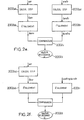
- the system consists of a generator module of reference signal, placed on the emission side upstream of transmission device, as shown and referenced 1 in Figures 3a and 3b.
- the transmission head of the network includes, in a conventional manner, particularly in the case non-limiting where the broadcast digital signal is a signal digital television signal type sn, a module of encoding of the MPEG type, this module being referenced MC and delivering a coded digital audio signal, noted snc.
- object of the present invention comprises, forming the generator of the reference signal mentioned above, a generator module 1 a reference signal from the original signal, the original signal being understood as the digital audio signal sn previously cited in the description.
- the system evaluation at reception includes, on the issue side, a module 2 for inserting the reference signal sref delivered by the module 1 generator of the reference signal in the train encoded digital audio signal snc issued by the MPEG coding module with reference MC in the figure 3a.
- the module 2 for inserting the reference signal sref in the coded digital audio signal stream snc allows to generate a bit stream that can be broadcast thanks to conventional means of emission, which are not represented in Figure 3a above.
- the evaluation system upon receipt of the quality of the distributed digital audio signal may comprise a encoded digital audio signal decoding module snc, this decoding module with the reference MDEC and ensuring a MPEG decoding for a digital television signal when it is coded according to the MPEG coding protocol.
- the MDEC decoding module delivers a digital audio signal reconstituted, noted sn *.
- the system for evaluating the reception of the quality of the broadcasted digital audio signal can advantageously comprise a module, denoted 1a, for assessing the quality a priori of the coded signal. transmission, this evaluation module a priori receiving the reconstituted digital audio signal sn * and the reference signal sref to deliver a signal representative of the quality of the coded transmission signal, this signal being of course representative of the quality a priori of the aforementioned coded transmission signal. It is indicated that the module 1 generator sref reference signal and the quality assessment module 1 has a priori is in fact an audio analyzer.
- FIG. 3b a variant of FIG. realization of the reference signal generator module represented in FIG. 3a, in a particular case specific in which this module is implemented directly downstream of the MPEG encoding module MC for a digital television signal.
- this module is implemented directly downstream of the MPEG encoding module MC for a digital television signal.
- the whole can be simplified compared to the embodiment of the FIG. 3a insofar as the implementation of the device represented in FIG. 3b is made from the signal coded digital audio snc previously mentioned in connection with Figure 3a.
- the evaluation module of the prior quality of the coded transmission signal can be deleted for simplification. In these conditions, found, in the embodiment of Figure 3b, the MPEC decoding type MDEC decoding module previously mentioned in connection with FIG.
- this module delivering the reconstituted digital audio signal sn * substantially identical to that shown in Figure 3a.
- the generator module of the reference signal 1, in the audio analyzer delivers From this last signal, the reference signal sref at reference signal insertion module 2, which delivers in the same way the coded digital audio signal snc in which has been inserted the reference signal sref for constitute the bitstream to be broadcast, as mentioned previously in connection with Figure 3a.
- the coded digital audio signal snc and the reference sref are substantially or, at the very least, coarsely synchronized, insertion and transmission of the reference signal in the bit stream of the signal encoded digital audio snc conserving globally this synchronization with a precision large enough to allow to define the synchronization probability range P previously mentioned in the description relatively to the implementation of the process, object of this invention.
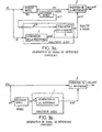
- the evaluation system upon receipt of the the quality of a broadcast digital audio signal the present invention comprises, as shown in FIG. 3c, at the point of reception of the transmission network and downstream of a reception device of this network of transmitted digital audio signal transmission, a module quality evaluation in reception.
- the receiving device delivers a digital train formed by a received coded digital audio signal, noted snr in the figure 3c, and a received reference signal, noted srefr.
- the evaluation system upon receipt of quality the broadcast digital audio signal which is the subject of this invention, then comprises at least, forming the module referred to above, an auxiliary module of decoding of the received coded digital audio signal, this module decoding aid being noted MDEC and delivering a encoded-decoded digital audio signal received, noted snr *.
- the decoding module MDEC is an MPEG decoding module, which delivers the encoded-decoded digital audio signal received, noted snr *.
- the quality evaluation module also includes as shown in FIG. 3c, a module bearing the reference 3 of extraction of the reference signal received, receiving the aforementioned digital train snr, srefr and delivering a control reference signal, noted srefc.
- a module 4 for evaluating the quality of the transmission the broadcast digital audio signal receives the signal encoded-decoded digital audio received snr * and the signal from control reference srefc and delivers, on the criterion of identity separating the coded-decoded digital audio signal from the signal control reference, a signal representative of a quality value at the posterior reception of the signal digital audio. This signal is noted Q in Figure 3c.
- the quality assessment module of the transmission of the broadcast digital audio signal 4 aforesaid is actually an audio analyzer when the signal coded digital to evaluate is a digital audio signal.
- the module 4 comprises a module for calculating the spectral power density of the control reference signal, delivering a signal representative of the spectral power density of the signal reference reference, this module bearing the reference 40a.
- the calculation module 40a is a module for calculating the power spectral density in barks, as mentioned previously in the description in the context of the implementation of the process, object of the present invention.
- the module 4 comprises a module 40b for calculating the power spectral density of the coded-decoded digital signal received snr * delivering a signal representative of the power spectral density of the coded-decoded digital signal received snr *.
- the calculation module 40b makes it possible to calculate the spectral power density in barks.
- the aforementioned modules 40a and 40b are further followed by module 41 for evaluating the quality of the digital signal, this module 41 comprising, as shown in FIG.
- a first spectrum spreading module 410 receiving the signal representative of the spectral power density of the reference signal via a switch 40c, this spreading module 410 delivering a first distance calculation signal, denoted sd 1 .
- a second spread spectrum module 411 is provided which receives the signal representative of the power spectral density of the received coded-decoded digital signal and delivers a second distance calculation signal sd 2 .
- a fine sync module 40d is interconnected between the second spreading module of spectrum 411 and the output of the calculation module 40a by via the switching element 40c and the output of the module 40b for calculating the power spectral density digital signal.
- the fine synchronization module performs in proper switch position of the switch 40c delivering to the latter the signal representative of the spectral power density of the reference signal, a synchronization of the two aforementioned signals, representative signal of the spectral density of the signal power of reference and signal representative of the spectral density of digital signal strength, similar to the operative previously described in connection with Figure 2d in the description, as part of the implementation of the process, object of the present invention.
- a digital signal encoded-decoded received synchronized is delivered to the second module spread spectrum 411.
- the module 41 comprises a distance calculation module 412 receiving the first and the second distance calculation signal sd 1 , sd 2 , and delivers the signal representative of a quality value to the reception, a posteriori quality of the signal. digital audio.
Landscapes
- Engineering & Computer Science (AREA)
- Signal Processing (AREA)
- Quality & Reliability (AREA)
- Computer Networks & Wireless Communication (AREA)
- Testing, Inspecting, Measuring Of Stereoscopic Televisions And Televisions (AREA)
- Detection And Prevention Of Errors In Transmission (AREA)
- Monitoring And Testing Of Transmission In General (AREA)
- Synchronisation In Digital Transmission Systems (AREA)
- Reduction Or Emphasis Of Bandwidth Of Signals (AREA)
Description
- la figure 1 représente un schéma synoptique illustratif de la mise en oeuvre du procédé, objet de la présente invention ;
- la figure 2a représente un détail de mise en oeuvre spécifique du procédé, objet de la présente invention, pour une évaluation de la qualité de transmission en temps réel de manière discrète ou discontinue ;
- la figure 2b représente un détail de mise en oeuvre spécifique du procédé, objet de l'invention, dans un mode de réalisation préférentiel permettant une évaluation de la qualité de transmission en temps réel de manière sensiblement continue ;
- la figure 2c représente, de manière illustrative, un exemple spécifique de relation temporelle entre un signal numérique diffusé reçu, à évaluer, et un signal de référence diffusé reçu, permettant d'effectuer un calcul de distance en continu entre ces deux signaux ;
- la figure 2d représente, de manière illustrative, un processus de synchronisation fine entre le signal de référence diffusé reçu et le signal numérique diffusé reçu, permettant une mise en relation temporelle de ces signaux, telle que par exemple représentée en figure 2c ;
- la figure 2e représente un mode opératoire non limitatif permettant de réaliser l'étape de calcul de distance entre le signal de référence diffusé reçu et le signal numérique diffusé reçu représentée en figure 1 ;
- la figure 2f représente une variante de réalisation du mode opératoire représenté en figure 2e mise en oeuvre lorsque le signal de référence est formé par un signal de densité spectrale de puissance calculé à l'émission ;
- les figures 3a et 3b représentent, dans un réseau de transmission par diffusion d'un signal numérique, un dispositif d'évaluation, à la réception, placé côté émission, de la qualité de la diffusion de ce signal numérique dans un premier mode, respectivement un deuxième mode de réalisation ;
- la figure 3c représente, dans un réseau de transmission par diffusion d'un signal numérique, un dispositif d'évaluation, à la réception, placé côté réception, de la qualité de la diffusion de ce signal numérique ;
- la figure 3d représente un détail de réalisation de la figure 3c.

- N
- désigne le nombre de tranches temporelles successives, sur lequel la moyenne est calculée,
- M
- désigne un nombre entier, supérieur à 1,
Claims (18)
- Procédé d'évaluation, à la réception, de la qualité d'un signal numérique (sn) diffusé en émission à partir d'un signal d'origine (so), caractérisé en ce que ce procédé consiste :à l'émission,à engendrer (1001) un signal de référence (sref) représentatif dudit signal d'origine ;à diffuser conjointement (1002) ledit signal numérique (sn) et ledit signal de référence (sref), età la réception,à synchroniser (2001) ledit signal numérique diffusé reçu (snr) et ledit signal de référence diffusé reçu (srefr) ;à calculer (2002) une valeur de différence entre ledit signal numérique diffusé reçu (snr) et ledit signal de référence diffusé reçu (srefr) ;à estimer (2003), sur critère de la valeur de différence, une qualité de la réception dudit signal numérique.
- Procédé selon la revendication 1, caractérisé en ce que, à la réception :on calcule (2002) une valeur de distance séparant ledit signal numérique diffusé reçu (snr) dudit signal de référence diffusé reçu (srefr) ; eton attribue (2003), sur critère de valeur de ladite valeur de distance, une valeur de qualité à la réception dudit signal numérique.
- Procédé selon la revendication 1, caractérisé en ce que, pour une évaluation en temps réel non continue de la qualité d'un signal numérique (sn) diffusé en émission, l'étape de génération dudit signal de référence consiste à engendrer (1001a) une séquence de signal numérique arbitraire, ladite séquence arbitraire étant en outre constitutive dudit signal d'origine (so), ladite étape (2002) de calcul d'une valeur de différence entre le signal numérique diffusé reçu (snr) et le signal de référence diffusé reçu (srefr) étant conduite entre ce signal numérique diffusé reçu et ladite séquence arbitraire.
- Procédé selon la revendication 2, caractérisé en ce que, pour une évaluation en temps réel de la qualité d'un signal numérique diffusé en émission, l'étape de génération dudit signal de référence consiste :à échantillonner (1001a') par tranches temporelles successives discrètes ledit signal d'origine (so) ;à diffuser conjointement certaines tranches temporelles successives (1001b'), (1001c'), (1002) avec le signal numérique, pour constituer ledit signal de référence (sref).
- Procédé selon les revendications 2 et 4, caractérisé en ce que ladite étape de calcul de la valeur de distance consiste :à calculer la distance élémentaire di séparant des tranches temporelles du signal numérique diffusé reçu (snr) de tranches temporelles correspondantes du signal de référence diffusé reçu (srefr) ;à calculer la moyenne temporelle des distances élémentaires de l'ensemble des tranches temporelles.
- Procédé selon l'une des revendications 4 et 5, caractérisé en ce que, pour une diffusion conjointe périodique de certaines tranches temporelles successives à raison d'une tranche temporelle parmi M tranches temporelles successives, pour constituer ledit signal de référence (sref), ladite valeur de différence entre ledit signal numérique diffusé reçu (snr) et ledit signal de référence (sref) vérifie la relation :relation dans laquelle :

- N
- désigne le nombre de tranches temporelles successives,
- M
- désigne un nombre entier, supérieur à 1.
- Procédé selon l'une des revendications 2 à 6, caractérisé en ce que, pour une évaluation en temps réel de la qualité d'un signal numérique diffusé, ladite étape de synchronisation du signal numérique diffusé reçu et du signal de référence diffusé reçu consiste, à partir d'une plage temporelle (P) déterminée de vraisemblance du synchronisme de ce signal numérique diffusé reçu (snr) et du signal de référence diffusé reçu (srefr) :à subdiviser ledit signal numérique diffusé reçu (snr) pendant chaque plage temporelle en tranches temporelles T0 à TF successives décalées d'une valeur temporelle maximale δTk correspondant à l'incertitude maximale admissible de synchronisation effective entre ledit signal numérique diffusé reçu (snr) et ledit signal de référence (srefr) ;à calculer une distance entre chaque tranche temporelle successive décalée Tk dudit signal numérique diffusé reçu (snr) et ledit signal de référence (srefr) ;à retenir comme valeur de synchronisation le rang is de la tranche temporelle dudit signal numérique diffusé reçu pour lequel la distance calculée avec ledit signal de référence est minimale, selon la relation min dTk ⇒ is = k.
- Procédé selon la revendication 7, caractérisé en ce que ladite distance est l'écart à la valeur de l'unité de la fonction d'inter-corrélation respectivement la distance perceptuelle pour un signal audionumérique entre chaque tranche temporelle successive Tk décalée et le signal de référence Rj.
- Procédé selon la revendication 8, caractérisé en ce que, pour un signal de référence (srefr) constitué par certaines tranches temporelles successives du signal d'origine, de valeur temporelle déterminée, lesdites tranches temporelles successives décalées ont une valeur temporelle égale à ladite valeur temporelle déterminée, la valeur de la fonction d'intercorrélation étant calculée entre chaque tranche temporelle successive décalée du signal numérique diffusé reçu et chacune desdites certaines tranches temporelles successives du signal d'origine constitutives du signal de référence.
- Procédé selon l'une des revendications 1 à 9, caractérisé en ce que ladite étape de calcul de différence comporte le calcul d'une différence entre densités spectrales de puissance respectives du signal de référence diffusé reçu (srefr) et du signal numérique diffusé reçu (snr).
- Procédé selon les revendications 2 et 10, caractérisé en ce que ladite étape de calcul de distance consiste, pour au moins une tranche temporelle dudit signal numérique diffusé reçu :à calculer (2002a1) la densité spectrale de puissance du signal de référence diffusé reçu (srefr) pour engendrer un signal de densité spectrale de puissance du signal de référence diffusé reçu, respectivement (2002a2) du signal numérique diffusé reçu (snr) ;à appliquer à chaque signal de densité spectrale de puissance (dsrefr, dsnr) un traitement d'étalement de spectre de fréquence (2002b1, 2002b2) pour engendrer un signal de densité spectrale de puissance étalée du signal de référence, respectivement un signal de densité spectrale de puissance étalée du signal numérique diffusé reçu ;à comparer (2002c) le signal de densité spectrale de puissance étalée du signal de référence diffusé reçu et le signal de densité spectrale de puissance étalée du signal numérique diffusé reçu pour engendrer (2002d) une valeur de distance (D).
- Procédé selon l'une des revendications 3 à 11, caractérisé en ce que, pour un signal numérique formé par un signal audionumérique, ladite étape de génération dudit signal de référence consiste :à échantillonner par tranches temporelles successives discrètes ledit signal d'origine ;à calculer pour chaque tranche temporelle successive discrète échantillonnée la densité spectrale de puissance pour engendrer un signal de densité spectrale de puissance de chaque tranche échantillonnée ;à diffuser conjointement avec le signal audionumérique ledit signal de densité spectrale de puissance de chaque tranche échantillonnée pour constituer ledit signal de référence, ce qui permet de réduire le débit numérique nécessaire à la transmission du signal de référence.
- Procédé selon les revendications 2 et 12, caractérisé en ce que ladite étape de calcul de distance consiste, pour au moins une tranche temporelle dudit signal de référence diffusé reçu, constitué par ledit signal de densité spectrale de puissance de chaque tranche échantillonnée :à calculer (200a2) la densité spectrale de puissance du signal audionumérique diffusé reçu (snr) pour engendrer un signal de densité spectrale de puissance du signal audionumérique diffusé reçu (dsnr) ;à appliquer (200b1) au signal de référence diffusé reçu, constitué par ledit signal de densité spectrale de puissance de chaque tranche échantillonnée et au signal de densité spectrale de puissance du signal audionumérique diffusé reçu, un traitement (200b1, 200b2) d'étalement de spectre de fréquence pour engendrer un signal de densité spectrale de puissance étalée du signal de référence, respectivement un signal de densité spectrale de puissance étalée du signal audionumérique diffusé reçu ;à comparer (2002d) le signal de densité spectrale de puissance étalée du signal de référence diffusé reçu et le signal de densité spectrale de puissance étalée du signal audionumérique diffusé reçu pour engendrer une valeur de distance (D).
- Système d'évaluation de la qualité d'un signal audionumérique (sn) diffusé en émission à partir d'un signal d'origine (so), dans un réseau de transmission par diffusion comportant, côté émission et en amont d'un dispositif d'émission dudit signal audionumérique diffusé, des moyens (MC) de codage dudit signal d'origine en un signal numérique codé (snc),
caractérisé en ce qu'il comporte au moins, en amont dudit dispositif d'émission :des moyens (1) générateurs d'un signal de référence (sref), à partir dudit signal d'origine (so),et, recevant ledit signal audionumérique codé (snc) et ledit signal de référence (sref), des moyens (2) d'insertion dudit signal de référence (sref) dans le train numérique dudit signal numérique codé (snc), pour engendrer un signal codé d'émission (snc,sref), permettant d'engendrer ledit signal audionumérique diffusé. - Système d'évaluation selon la revendication 14, caractérisé en ce que celui-ci comporte en outre :des moyens (MDEC) de décodage du signal numérique codé délivrant un signal numérique reconstitué (sn*) ;des moyens (1a) d'évaluation de la qualité a priori du signal codé d'émission, lesdits moyens (1a) d'évaluation a priori recevant ledit signal numérique reconstitué (sn*) et ledit signal de référence (sref) et délivrant un signal représentatif de la qualité du signal codé d'émission.
- Système d'évaluation selon l'une des revendications 14 et 15, destiné à un réseau de transmission par diffusion d'un signal numérique diffusé en émission à partir d'un signal d'origine, ce signal numérique diffusé étant formé à partir d'un signal numérique codé dans lequel est inséré un signal de référence (sref) représentatif de ce signal d'origine, ce réseau de transmission comportant un dispositif de réception de ce signal numérique diffusé délivrant un train numérique formé par un signal numérique codé reçu (snr) et un signal de référence reçu (srefr),
caractérisé en ce qu'il comporte en outre, en aval dudit dispositif de réception, au moins :des moyens auxiliaires (MDEC) de décodage dudit signal numérique codé reçu (snr) recevant ledit signal numérique codé reçu et délivrant un signal numérique codé - décodé (snr*) ;des moyens (3) d'extraction dudit signal de référence diffusé reçu (srefr) recevant ledit train numérique et délivrant un signal de référence de contrôle (srefc);des moyens (4) d'évaluation de la qualité de la transmission du signal numérique diffusé recevant ledit signal numérique codé - décodé (snr*) et ledit signal de référence de contrôle (srefc), et délivrant, sur critère de valeur de différence entre ledit signal numérique codé - décodé (snr*) et ledit signal de référence de contrôle (srefc), un signal (Q) représentatif d'une valeur de qualité à la réception, a posteriori dudit signal numérique. - Système d'évaluation selon la revendication 16, caractérisé en ce que la valeur de différence est une valeur de distance entre ledit signal numérique codé - décodé (snr*) et ledit signal de référence de contrôle (srefc).
- Système d'évaluation selon la revendication 17, caractérisé en ce que lesdits moyens (4) d'évaluation de la qualité de la transmission du signal numérique diffusé comprennent au moins :des moyens de calcul (40a) de la densité spectrale de puissance du signal de référence de contrôle (srefc) délivrant un signal représentatif de la densité spectrale de puissance du signal de référence de contrôle ;des premiers moyens (410) d'étalement de spectre recevant le signal représentatif de la densité spectrale de puissance du signal de référence de contrôle et délivrant un premier signal (sd1) de calcul de la distance ;des moyens de calcul (40b) de la densité spectrale de puissance dudit signal numérique codé - décodé (snr*) délivrant un signal représentatif de la densité spectrale de puissance du signal numérique codé - décodé ;des deuxièmes moyens (411) d'étalement de spectre recevant le signal représentatif de la densité spectrale de puissance du signal numérique codé - décodé et délivrant un deuxième signal (sd2) de calcul de distance ;des moyens de calcul (412) de distance recevant le premier (sd1) et le deuxième (sd2) signal de calcul de distance et délivrant ledit signal (Q) représentatif d'une valeur de qualité à la réception a posteriori dudit signal audionumérique.
Applications Claiming Priority (3)
| Application Number | Priority Date | Filing Date | Title |
|---|---|---|---|
| FR9712763A FR2769777B1 (fr) | 1997-10-13 | 1997-10-13 | Procede et systeme d'evaluation, a la reception, de la qualite d'un signal numerique, tel qu'un signal audio/video numerique |
| FR9712763 | 1997-10-13 | ||
| PCT/FR1998/002179 WO1999020017A1 (fr) | 1997-10-13 | 1998-10-12 | Procede et systeme d'evaluation, a la reception, de la qualite d'un signal numerique, tel qu'un signal audio/video numerique |
Publications (2)
| Publication Number | Publication Date |
|---|---|
| EP1025667A1 EP1025667A1 (fr) | 2000-08-09 |
| EP1025667B1 true EP1025667B1 (fr) | 2005-07-20 |
Family
ID=9512149
Family Applications (1)
| Application Number | Title | Priority Date | Filing Date |
|---|---|---|---|
| EP98947644A Expired - Lifetime EP1025667B1 (fr) | 1997-10-13 | 1998-10-12 | Procede et systeme d'evaluation, a la reception, de la qualite d'un signal numerique, tel qu'un signal audio/video numerique |
Country Status (8)
| Country | Link |
|---|---|
| US (1) | US6549757B1 (fr) |
| EP (1) | EP1025667B1 (fr) |
| JP (1) | JP4122131B2 (fr) |
| AT (1) | ATE300133T1 (fr) |
| CA (1) | CA2305983C (fr) |
| DE (1) | DE69830918T2 (fr) |
| FR (1) | FR2769777B1 (fr) |
| WO (1) | WO1999020017A1 (fr) |
Families Citing this family (11)
| Publication number | Priority date | Publication date | Assignee | Title |
|---|---|---|---|---|
| FR2799321B1 (fr) * | 1999-10-01 | 2002-01-04 | France Telecom | Procede de controle en continu de la qualite des sons numeriques en distribution |
| FR2802370B1 (fr) * | 1999-12-13 | 2002-01-18 | Telediffusion Fse | Surveillance de la qualite de service dans une liaison de television numerique |
| DE10035041B4 (de) * | 2000-07-19 | 2006-07-13 | Robert Bosch Gmbh | Verfahren zur Einstellung von Sendeparametern von einem Sender für digitale Rundfunksignale |
| FR2835125B1 (fr) * | 2002-01-24 | 2004-06-18 | Telediffusion De France Tdf | Procede d'evaluation d'un signal audio numerique |
| US7356186B2 (en) * | 2002-08-23 | 2008-04-08 | Kulas Charles J | Digital representation of audio waveforms using peak shifting to provide increased dynamic range |
| US7394940B2 (en) * | 2004-11-19 | 2008-07-01 | International Business Machines Corporation | Digital video media duplication or transmission quality measurement |
| KR100628835B1 (ko) * | 2005-02-26 | 2006-09-26 | 한국정보통신기술협회 | 시나리오 기반의 데이터 방송 수신기 시험 자동화 장치 및방법 |
| DE102006044929B4 (de) * | 2006-09-22 | 2008-10-23 | Opticom Dipl.-Ing. Michael Keyhl Gmbh | Vorrichtung zum Bestimmen von Informationen zur zeitlichen Ausrichtung zweier Informationssignale |
| US20110276882A1 (en) | 2010-05-04 | 2011-11-10 | Kai Buehler | Automatic grouping for users experiencing a specific broadcast media |
| WO2013012952A1 (fr) | 2011-07-18 | 2013-01-24 | Viggle Inc | Système et procédé pour tracer et récompenser une utilisation de médias et de divertissements comprenant des récompenses sensiblement en temps réel |
| US9024739B2 (en) * | 2012-06-12 | 2015-05-05 | Guardity Technologies, Inc. | Horn input to in-vehicle devices and systems |
Family Cites Families (13)
| Publication number | Priority date | Publication date | Assignee | Title |
|---|---|---|---|---|
| JPS5329417B2 (fr) * | 1973-02-26 | 1978-08-21 | ||
| US3988670A (en) * | 1975-04-15 | 1976-10-26 | The United States Of America As Represented By The Secretary Of The Navy | Automatic testing of digital logic systems |
| AU525766B2 (en) * | 1978-11-15 | 1982-12-02 | Australian Telecommunications Commission | Noise assessment of pcm regenerator |
| US5790523A (en) * | 1993-09-17 | 1998-08-04 | Scientific-Atlanta, Inc. | Testing facility for a broadband communications system |
| US5790717A (en) * | 1993-10-26 | 1998-08-04 | Bell Communications Research Inc. | Apparatus and method for predicting subjective quality of compressed images |
| FR2713425A1 (fr) * | 1993-11-30 | 1995-06-09 | Sedeca | Procédé et dispositif de contrôle de message d'attente musicale. |
| US5859874A (en) * | 1994-05-09 | 1999-01-12 | Globalstar L.P. | Multipath communication system optimizer |
| IL114471A0 (en) * | 1994-07-12 | 1996-01-31 | Usa Digital Radio Partners L P | Method and system for simultaneously broadcasting and analog signals |
| JP3333053B2 (ja) * | 1994-09-05 | 2002-10-07 | 富士通株式会社 | ディジタル通信装置 |
| US5802105A (en) * | 1994-11-30 | 1998-09-01 | Qualcomm Incorporated | Method and apparatus for testing a digital communication channel |
| WO1996031009A1 (fr) * | 1995-03-27 | 1996-10-03 | Celsat America, Inc. | Systeme de commande de puissance de communication cellulaire |
| ZA965340B (en) * | 1995-06-30 | 1997-01-27 | Interdigital Tech Corp | Code division multiple access (cdma) communication system |
| US5949796A (en) * | 1996-06-19 | 1999-09-07 | Kumar; Derek D. | In-band on-channel digital broadcasting method and system |
-
1997
- 1997-10-13 FR FR9712763A patent/FR2769777B1/fr not_active Expired - Fee Related
-
1998
- 1998-10-12 CA CA002305983A patent/CA2305983C/fr not_active Expired - Fee Related
- 1998-10-12 DE DE69830918T patent/DE69830918T2/de not_active Expired - Lifetime
- 1998-10-12 EP EP98947644A patent/EP1025667B1/fr not_active Expired - Lifetime
- 1998-10-12 WO PCT/FR1998/002179 patent/WO1999020017A1/fr not_active Ceased
- 1998-10-12 US US09/529,308 patent/US6549757B1/en not_active Expired - Lifetime
- 1998-10-12 AT AT98947644T patent/ATE300133T1/de not_active IP Right Cessation
- 1998-10-12 JP JP2000516462A patent/JP4122131B2/ja not_active Expired - Fee Related
Also Published As
| Publication number | Publication date |
|---|---|
| EP1025667A1 (fr) | 2000-08-09 |
| FR2769777B1 (fr) | 1999-12-24 |
| DE69830918D1 (de) | 2005-08-25 |
| JP2001520481A (ja) | 2001-10-30 |
| ATE300133T1 (de) | 2005-08-15 |
| DE69830918T2 (de) | 2006-04-20 |
| CA2305983A1 (fr) | 1999-04-22 |
| JP4122131B2 (ja) | 2008-07-23 |
| CA2305983C (fr) | 2008-02-19 |
| WO1999020017A1 (fr) | 1999-04-22 |
| US6549757B1 (en) | 2003-04-15 |
| FR2769777A1 (fr) | 1999-04-16 |
Similar Documents
| Publication | Publication Date | Title |
|---|---|---|
| EP0768770B1 (fr) | Procédé et dispositif de création d'un bruit de confort dans un système de transmission numérique de parole | |
| EP1468416B1 (fr) | Procede d'evaluation qualitative d'un signal audio numerique. | |
| EP1987513B1 (fr) | Procede et dispositif de codage hierarchique d'un signal audio source, procede et dispositif de decodage, programmes et signal correspondants | |
| WO1999020017A1 (fr) | Procede et systeme d'evaluation, a la reception, de la qualite d'un signal numerique, tel qu'un signal audio/video numerique | |
| EP0906613B1 (fr) | Procede et dispositif de codage d'un signal audiofrequence par analyse lpc "avant" et "arriere" | |
| EP2811749A1 (fr) | Synchronisation de contenus multimédia sur deuxième écran | |
| WO2017089690A1 (fr) | Procédé de synchronisation d'un flux audio alternatif | |
| EP1356455B1 (fr) | Methode et dispositif de traitement d'une pluralite de flux binaires audio | |
| EP1468573A1 (fr) | Procede de synchronisation de deux flux de donnees numeriques de meme contenu. | |
| WO2002035855A1 (fr) | Procede de synchronisation de signaux numeriques. | |
| EP1009105A1 (fr) | Récepteur, système de télécommunications CDMA et procédé de synchronisation d'un récepteur avec une station d'émission d'un tel système | |
| WO2001091462A1 (fr) | Dispositif et procede de synchronisation de programmes audiovisuels diffuses et d'informations complementaires | |
| EP1159795B1 (fr) | Procede de controle de la qualite d'un signal audionumerique diffuse avec un programme audiovisuel | |
| FR2956787A1 (fr) | Procede et serveur pour detecter un programme video recu par un usager | |
| FR2962875A1 (fr) | Diffusion synchronisee de flux | |
| EP0322059A1 (fr) | Procédé et système de brouillage/désembrouillage du son | |
| WO2020188097A1 (fr) | Procédé de restitution de contenus de personnalisation d'un flux radiophonique principal | |
| FR2718586A1 (fr) | Diffusion de données cyclique et cellulaire. | |
| FR2721160A1 (fr) | Procédé d'embrouillage et de désembrouillage de programmes de télévision multiplexée et dispositifs correspondants. | |
| FR2730111A1 (fr) | Procede d'emission-reception de donnees d'information, notamment en radiophonie, et systeme d'emission-reception pour la mise en oeuvre d'un tel procede | |
| FR2954639A1 (fr) | Procede d'emission et de rendu de sequences numeriques formant une grille de programmation | |
| FR2965433A1 (fr) | Dispositif et procede de datation d’un evenement dans un flux de donnees d’un contenu audio ou audiovisuel | |
| WO2013014381A1 (fr) | Procede et dispositif de generation d'un signal porteur d'un code numerique |
Legal Events
| Date | Code | Title | Description |
|---|---|---|---|
| PUAI | Public reference made under article 153(3) epc to a published international application that has entered the european phase |
Free format text: ORIGINAL CODE: 0009012 |
|
| 17P | Request for examination filed |
Effective date: 20000330 |
|
| AK | Designated contracting states |
Kind code of ref document: A1 Designated state(s): AT BE CH CY DE DK ES FI FR GB GR IE IT LI LU MC NL PT SE |
|
| 17Q | First examination report despatched |
Effective date: 20040309 |
|
| GRAP | Despatch of communication of intention to grant a patent |
Free format text: ORIGINAL CODE: EPIDOSNIGR1 |
|
| RIN1 | Information on inventor provided before grant (corrected) |
Inventor name: BAINA, JAMAL Inventor name: MASSE, DENIS |
|
| GRAS | Grant fee paid |
Free format text: ORIGINAL CODE: EPIDOSNIGR3 |
|
| RAP1 | Party data changed (applicant data changed or rights of an application transferred) |
Owner name: TDF |
|
| GRAA | (expected) grant |
Free format text: ORIGINAL CODE: 0009210 |
|
| AK | Designated contracting states |
Kind code of ref document: B1 Designated state(s): AT BE CH CY DE DK ES FI FR GB GR IE IT LI LU MC NL PT SE |
|
| PG25 | Lapsed in a contracting state [announced via postgrant information from national office to epo] |
Ref country code: IE Free format text: LAPSE BECAUSE OF FAILURE TO SUBMIT A TRANSLATION OF THE DESCRIPTION OR TO PAY THE FEE WITHIN THE PRESCRIBED TIME-LIMIT Effective date: 20050720 Ref country code: FI Free format text: LAPSE BECAUSE OF FAILURE TO SUBMIT A TRANSLATION OF THE DESCRIPTION OR TO PAY THE FEE WITHIN THE PRESCRIBED TIME-LIMIT Effective date: 20050720 Ref country code: AT Free format text: LAPSE BECAUSE OF FAILURE TO SUBMIT A TRANSLATION OF THE DESCRIPTION OR TO PAY THE FEE WITHIN THE PRESCRIBED TIME-LIMIT Effective date: 20050720 |
|
| REG | Reference to a national code |
Ref country code: GB Ref legal event code: FG4D Free format text: NOT ENGLISH |
|
| REG | Reference to a national code |
Ref country code: CH Ref legal event code: EP |
|
| REG | Reference to a national code |
Ref country code: IE Ref legal event code: FG4D Free format text: LANGUAGE OF EP DOCUMENT: FRENCH |
|
| REF | Corresponds to: |
Ref document number: 69830918 Country of ref document: DE Date of ref document: 20050825 Kind code of ref document: P |
|
| PG25 | Lapsed in a contracting state [announced via postgrant information from national office to epo] |
Ref country code: CY Free format text: LAPSE BECAUSE OF FAILURE TO SUBMIT A TRANSLATION OF THE DESCRIPTION OR TO PAY THE FEE WITHIN THE PRESCRIBED TIME-LIMIT Effective date: 20051012 |
|
| GBT | Gb: translation of ep patent filed (gb section 77(6)(a)/1977) |
Effective date: 20050928 |
|
| PG25 | Lapsed in a contracting state [announced via postgrant information from national office to epo] |
Ref country code: SE Free format text: LAPSE BECAUSE OF FAILURE TO SUBMIT A TRANSLATION OF THE DESCRIPTION OR TO PAY THE FEE WITHIN THE PRESCRIBED TIME-LIMIT Effective date: 20051020 Ref country code: GR Free format text: LAPSE BECAUSE OF FAILURE TO SUBMIT A TRANSLATION OF THE DESCRIPTION OR TO PAY THE FEE WITHIN THE PRESCRIBED TIME-LIMIT Effective date: 20051020 Ref country code: DK Free format text: LAPSE BECAUSE OF FAILURE TO SUBMIT A TRANSLATION OF THE DESCRIPTION OR TO PAY THE FEE WITHIN THE PRESCRIBED TIME-LIMIT Effective date: 20051020 |
|
| PG25 | Lapsed in a contracting state [announced via postgrant information from national office to epo] |
Ref country code: MC Free format text: LAPSE BECAUSE OF NON-PAYMENT OF DUE FEES Effective date: 20051031 Ref country code: LU Free format text: LAPSE BECAUSE OF NON-PAYMENT OF DUE FEES Effective date: 20051031 Ref country code: LI Free format text: LAPSE BECAUSE OF NON-PAYMENT OF DUE FEES Effective date: 20051031 Ref country code: ES Free format text: LAPSE BECAUSE OF FAILURE TO SUBMIT A TRANSLATION OF THE DESCRIPTION OR TO PAY THE FEE WITHIN THE PRESCRIBED TIME-LIMIT Effective date: 20051031 Ref country code: CH Free format text: LAPSE BECAUSE OF NON-PAYMENT OF DUE FEES Effective date: 20051031 |
|
| PG25 | Lapsed in a contracting state [announced via postgrant information from national office to epo] |
Ref country code: PT Free format text: LAPSE BECAUSE OF FAILURE TO SUBMIT A TRANSLATION OF THE DESCRIPTION OR TO PAY THE FEE WITHIN THE PRESCRIBED TIME-LIMIT Effective date: 20051221 |
|
| REG | Reference to a national code |
Ref country code: IE Ref legal event code: FD4D |
|
| PLBE | No opposition filed within time limit |
Free format text: ORIGINAL CODE: 0009261 |
|
| STAA | Information on the status of an ep patent application or granted ep patent |
Free format text: STATUS: NO OPPOSITION FILED WITHIN TIME LIMIT |
|
| REG | Reference to a national code |
Ref country code: CH Ref legal event code: PL |
|
| 26N | No opposition filed |
Effective date: 20060421 |
|
| REG | Reference to a national code |
Ref country code: FR Ref legal event code: PLFP Year of fee payment: 18 |
|
| REG | Reference to a national code |
Ref country code: FR Ref legal event code: PLFP Year of fee payment: 19 |
|
| PGFP | Annual fee paid to national office [announced via postgrant information from national office to epo] |
Ref country code: NL Payment date: 20160923 Year of fee payment: 19 Ref country code: GB Payment date: 20160928 Year of fee payment: 19 |
|
| PGFP | Annual fee paid to national office [announced via postgrant information from national office to epo] |
Ref country code: FR Payment date: 20160921 Year of fee payment: 19 |
|
| PGFP | Annual fee paid to national office [announced via postgrant information from national office to epo] |
Ref country code: BE Payment date: 20160923 Year of fee payment: 19 |
|
| PGFP | Annual fee paid to national office [announced via postgrant information from national office to epo] |
Ref country code: DE Payment date: 20160922 Year of fee payment: 19 |
|
| PGFP | Annual fee paid to national office [announced via postgrant information from national office to epo] |
Ref country code: IT Payment date: 20160923 Year of fee payment: 19 |
|
| REG | Reference to a national code |
Ref country code: DE Ref legal event code: R119 Ref document number: 69830918 Country of ref document: DE |
|
| REG | Reference to a national code |
Ref country code: NL Ref legal event code: MM Effective date: 20171101 |
|
| GBPC | Gb: european patent ceased through non-payment of renewal fee |
Effective date: 20171012 |
|
| REG | Reference to a national code |
Ref country code: FR Ref legal event code: ST Effective date: 20180629 |
|
| PG25 | Lapsed in a contracting state [announced via postgrant information from national office to epo] |
Ref country code: GB Free format text: LAPSE BECAUSE OF NON-PAYMENT OF DUE FEES Effective date: 20171012 Ref country code: DE Free format text: LAPSE BECAUSE OF NON-PAYMENT OF DUE FEES Effective date: 20180501 Ref country code: NL Free format text: LAPSE BECAUSE OF NON-PAYMENT OF DUE FEES Effective date: 20171101 |
|
| REG | Reference to a national code |
Ref country code: BE Ref legal event code: MM Effective date: 20171031 |
|
| PG25 | Lapsed in a contracting state [announced via postgrant information from national office to epo] |
Ref country code: BE Free format text: LAPSE BECAUSE OF NON-PAYMENT OF DUE FEES Effective date: 20171031 Ref country code: FR Free format text: LAPSE BECAUSE OF NON-PAYMENT OF DUE FEES Effective date: 20171031 |
|
| PG25 | Lapsed in a contracting state [announced via postgrant information from national office to epo] |
Ref country code: IT Free format text: LAPSE BECAUSE OF NON-PAYMENT OF DUE FEES Effective date: 20171012 |