EP1025424B2 - Weight filling device - Google Patents
Weight filling device Download PDFInfo
- Publication number
- EP1025424B2 EP1025424B2 EP98949076A EP98949076A EP1025424B2 EP 1025424 B2 EP1025424 B2 EP 1025424B2 EP 98949076 A EP98949076 A EP 98949076A EP 98949076 A EP98949076 A EP 98949076A EP 1025424 B2 EP1025424 B2 EP 1025424B2
- Authority
- EP
- European Patent Office
- Prior art keywords
- weight
- support member
- bar
- jaws
- container
- Prior art date
- Legal status (The legal status is an assumption and is not a legal conclusion. Google has not performed a legal analysis and makes no representation as to the accuracy of the status listed.)
- Expired - Lifetime
Links
Images
Classifications
-
- B—PERFORMING OPERATIONS; TRANSPORTING
- B67—OPENING, CLOSING OR CLEANING BOTTLES, JARS OR SIMILAR CONTAINERS; LIQUID HANDLING
- B67C—CLEANING, FILLING WITH LIQUIDS OR SEMILIQUIDS, OR EMPTYING, OF BOTTLES, JARS, CANS, CASKS, BARRELS, OR SIMILAR CONTAINERS, NOT OTHERWISE PROVIDED FOR; FUNNELS
- B67C3/00—Bottling liquids or semiliquids; Filling jars or cans with liquids or semiliquids using bottling or like apparatus; Filling casks or barrels with liquids or semiliquids
- B67C3/02—Bottling liquids or semiliquids; Filling jars or cans with liquids or semiliquids using bottling or like apparatus
- B67C3/20—Bottling liquids or semiliquids; Filling jars or cans with liquids or semiliquids using bottling or like apparatus with provision for metering the liquids to be introduced, e.g. when adding syrups
- B67C3/202—Bottling liquids or semiliquids; Filling jars or cans with liquids or semiliquids using bottling or like apparatus with provision for metering the liquids to be introduced, e.g. when adding syrups by weighing
-
- B—PERFORMING OPERATIONS; TRANSPORTING
- B67—OPENING, CLOSING OR CLEANING BOTTLES, JARS OR SIMILAR CONTAINERS; LIQUID HANDLING
- B67C—CLEANING, FILLING WITH LIQUIDS OR SEMILIQUIDS, OR EMPTYING, OF BOTTLES, JARS, CANS, CASKS, BARRELS, OR SIMILAR CONTAINERS, NOT OTHERWISE PROVIDED FOR; FUNNELS
- B67C3/00—Bottling liquids or semiliquids; Filling jars or cans with liquids or semiliquids using bottling or like apparatus; Filling casks or barrels with liquids or semiliquids
- B67C3/02—Bottling liquids or semiliquids; Filling jars or cans with liquids or semiliquids using bottling or like apparatus
- B67C3/22—Details
- B67C3/24—Devices for supporting or handling bottles
- B67C3/242—Devices for supporting or handling bottles engaging with bottle necks
-
- G—PHYSICS
- G01—MEASURING; TESTING
- G01G—WEIGHING
- G01G19/00—Weighing apparatus or methods adapted for special purposes not provided for in the preceding groups
- G01G19/14—Weighing apparatus or methods adapted for special purposes not provided for in the preceding groups for weighing suspended loads
- G01G19/18—Weighing apparatus or methods adapted for special purposes not provided for in the preceding groups for weighing suspended loads having electrical weight-sensitive devices
-
- G—PHYSICS
- G01—MEASURING; TESTING
- G01G—WEIGHING
- G01G3/00—Weighing apparatus characterised by the use of elastically-deformable members, e.g. spring balances
- G01G3/12—Weighing apparatus characterised by the use of elastically-deformable members, e.g. spring balances wherein the weighing element is in the form of a solid body stressed by pressure or tension during weighing
- G01G3/14—Weighing apparatus characterised by the use of elastically-deformable members, e.g. spring balances wherein the weighing element is in the form of a solid body stressed by pressure or tension during weighing measuring variations of electrical resistance
- G01G3/1402—Special supports with preselected places to mount the resistance strain gauges; Mounting of supports
-
- G—PHYSICS
- G01—MEASURING; TESTING
- G01G—WEIGHING
- G01G23/00—Auxiliary devices for weighing apparatus
- G01G23/005—Means for preventing overload
Definitions
- the holding member thus makes it possible to suspend the receptacle by the collar of the neck cantilever with respect to the support member associated with the weight sensor.
- the weighing device and therefore suitable for holding and weighing containers of different sizes.
- the weighing device can be arranged laterally with respect to the container so that the weighing device is weakly exposed to flows of the filling product out of the container that may occur during a malfunction, particularly when the container is pierced or when the filling spout is not closed.
- the collar is in this way punctual support on the upper surface of the jaws of the clamp.
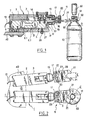
- the weight filling installation described below is intended for filling containers 50 having a neck 51 and a flange 52 extending outwardly projecting around the neck 51.
- the filling installation is of the carousel type and comprises a rotary platform 40 of the known type carrying a conventional filling circuit equipped with filling spouts 60 and weighing devices, generally designated 1, for holding the containers 50 to 50. the plumbs 60 filling and weigh the containers 50 during filling thereof.
- a bar 5 of elastically deformable material is fixed on the frame 1 bears on a portion 6.1 of the lower surface of the bar, adjacent to one end 7 of the bar 5 and projecting from the rest 6.2 of the lower surface.
- a support member generally designated 11 extends laterally relative to the frame 1 through an opening 12 formed in the part 3 of the housing.
- the support member 11 comprises an arm 13 whose end 14 is fixed on the upper face of the bar 5 by screws and the opposite end 16 carries a yoke 17.
- Two jaws 21 are mounted to pivot on the yoke 17 by means of screws 22 forming pivot axes so that a clamp is thus formed.
- a screw 27 equipped with a counter nut 8 is fixed in the bottom wall of the part 3 perpendicular to the lower surface of the bar 5 facing the lower face of the end 31 of the deformable bar 5.
- the weight of the container 50 suspended from the clamp is exerted on the end 31 of the bar 5 via the support member 11. This force causes a deformation of the bar 5 detected by the strain gauge.
- the adjustment of the screw 27 makes it possible to modify the maximum amplitude of deformation of the bar 5 by forming a stop for the part 6.2 of the lower surface of the bar 5.
- the part 3 forming the housing of the frame 1 comprises a lower inner surface raised relative to the lower inner surface of the part 2.
- the mounting of the elastic bar 5 is reversed compared to the previous assembly is that is to say that the end 7 of the bar 5 is fixed on the lower inner surface of the part 3 by screws.
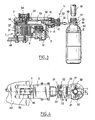
- the free end 31 of the bar 5 is connected by a link 37 to the end 14 of an arm 13 mounted to pivot in the part 3 on a pivot axis 32.
- the end portion 16 of the arm 13 carries similar to the first embodiment a yoke 17 and jaws 21 pivotally mounted on the yoke 17.
- the jaws 21 have an upper face provided with a prominent portion 38 formed by an edge extending along a diameter of the opening defined by the jaws 21, perpendicular to the longitudinal direction of the arm 13.
- a head screw 33 extends vertically through a hole in the upper wall of the portion 2 and is secured in the arm 13 on a side opposite the jaws 21 relative to the pivot axis 32.
- the head of the screw 33 thus forms a stop for a movement of the arm 13 in the counterclockwise direction.
- a screw 34 provided with a counter-nut is screwed into the upper wall of the part 2 on the same side of the axis 32 and has an end extending opposite the arm 13.
- the screw 34 forms a stop for the arm 13 clockwise.
- the operation of the weighing device according to the second embodiment is substantially identical to that described for the first embodiment.
- the zero of the weighing device is adjusted by putting the link 37 slightly under tension by an appropriate adjustment of the screw 33.
- the weight of the container here causes the pivoting of the arm 13 in the clockwise direction about the pivot axis 32.
- the end 14 then moves and drives via the link 37 the end 31 of the bar 5. This causes a deformation of the bar 5 detected by the strain gauge.
- the screw 34 limits the maximum deformation of the bar 5.
- the side wall of the neck 51 The gripping of the container by the clamp is thus essentially ensured by the support of the flange 52 on the prominences 38. Because of this arrangement, the container can tilt under the action of the centrifugal force when the platform 40 is rotating without changing the point of application of the weight of the container on the arm 13. The force resulting from the centrifugal force can therefore be corrected in a manner known per se by the processing members connected to the weight sensor.
Description
La présente invention concerne un dispositif de remplissage pondéral de récipients ayant un goulot et une collerette s'étendant autour du goulot, tels que des bouteilles.The present invention relates to a container filling device containers having a neck and a collar extending around the neck, such as bottles.
Les installations connues de remplissage pondéral de récipients a goulot comportent généralement un dispositif de pesage qui comprend un capteur de poids surmonté d'un plateau support de récipients. Le dispositif de pesage est disposé pour que le plateau supporte le fond du récipient de manière que le goulot de celui-ci soit positionné juste en dessous du bec de remplissage. Lorsque l'installation est destinée au remplissage de séries de récipients ayant des hauteurs différentes, la position du plateau du dispositif de pesage doit être réglée à chaque changement de série pour être adaptée à la hauteur des récipients de la nouvelle série. L'installation nécessite alors des moyens de réglage du positionnement du dispositif de pesage rendant l'installation coûteuse ou le réglage des dispositifs de pesage est réalisé manuellement et oblige alors à interrompre la production, ce qui entraîne une baisse de la productivité.The known weight filling installations of neck containers generally comprise a weighing device which comprises a weight sensor surmounted by a container support plate. The weighing device is arranged so that the tray supports the bottom of the container so that the neck thereof is positioned just below the filling spout. When the installation is intended for the filling of series of containers of different heights, the position of the platform of the weighing device must be adjusted at each change of series to be adapted to the height of the containers of the new series. The installation then requires means for adjusting the positioning of the weighing device making the installation expensive or the setting of the weighing devices is done manually and then forces to interrupt production, which results in a decrease in productivity.
Il est également connu du document
En l'absence de récipient le bras articulé est rappelé vers le haut et pour introduire un récipient il est donc nécessaire d'abaisser manuellement le bras articulé. Ce dispositif est donc totalement inutilisable dans une installation de remplissage où des récipients doivent être remplis en série. En outre, chaque fois qu'un nouveau récipient est utilisé il est nécessaire de remplacer le ressort par un nouveau ressort adapté au poids total du récipient et de la quantité de produit à introduire dans le récipient.In the absence of a container the articulated arm is raised upwards and to introduce a container it is therefore necessary to manually lower the articulated arm. This device is therefore totally unusable in a filling installation where containers must be filled in series. In addition, whenever a new container is used it is necessary to replace the spring with a new spring adapted to the total weight of the container and the amount of product to be introduced into the container.
Par ailleurs il est connu de nombreux documents, en particulier du document
Selon l'invention, on propose un dispositif de remplissage pondéral de récipients ayant un goulot cylindrique et une collerette s'étendant autour du goulot, le dispositif comprenant un dispositif de pesage comportant un élément de maintien ayant une surface supérieure formant un appui pour la collerette d'un récipient de façon que celui-ci s'étende à l'aplomb d'un bec de remplissage en porte-à-faux par rapport à un organe support s'étendant latéralement à partir du bâti, caractérisé en ce que l'organe support est associé à un capteur de poids comprenant un barreau élastiquement déformable ayant une extrémité rigidement fixée au bâti et une extrémité opposée reliée à l'organe support.According to the invention, there is provided a device for weighting containers with a cylindrical neck and a flange extending around the neck, the device comprising a weighing device comprising a holding member having an upper surface forming a support for the flange of a container so that it extends in line with the a filling spout cantilevered with respect to a support member extending laterally from the frame, characterized in that the support member is associated with a weight sensor comprising an elastically deformable bar having a rigidly rigid end fixed to the frame and an opposite end connected to the support member.
L'élément de maintien permet ainsi de suspendre le récipient par la collerette du goulot en porte-à-faux par rapport à l'organe support associé au capteur de poids. Le dispositif de pesage et donc adapté au maintien et au pesage de récipients de différents formats. Par ailleurs, le dispositif de pesage peut être disposé latéralement par rapport au récipient de sorte que le dispositif de pesage est faiblement exposé à des écoulements du produit de remplissage hors du récipient risquant de se produire lors d'une anomalie de fonctionnement, en particulier lorsque le récipient est percé ou lors d'un défaut de fermeture du bec de remplissage.The holding member thus makes it possible to suspend the receptacle by the collar of the neck cantilever with respect to the support member associated with the weight sensor. The weighing device and therefore suitable for holding and weighing containers of different sizes. Furthermore, the weighing device can be arranged laterally with respect to the container so that the weighing device is weakly exposed to flows of the filling product out of the container that may occur during a malfunction, particularly when the container is pierced or when the filling spout is not closed.
Selon un mode de réalisation particulier, l'élément de maintien comprend une pince ayant des mâchoires portant des butées disposées pour qu'en position de butée les mâchoires délimitent une ouverture ayant une dimension transversale supérieure à un diamètre du goulot et inférieure à un diamètre de la collerette, de préférence alors, les mâchoires ont une face supérieure pourvue d'une partie proéminente.According to a particular embodiment, the holding element comprises a clamp having jaws bearing abutments arranged so that in the stop position the jaws delimit an opening having a transverse dimension greater than a diameter of the neck and less than a diameter of the flange, preferably then, the jaws have an upper face provided with a prominent portion.
La collerette est de la sorte en appui ponctuel sur la surface supérieure des mâchoires de la pince. Lorsque le dispositif de pesage est monté sur une plate-forme rotative, cette disposition permet d'éviter une variation du point d'application du poids du récipient lors d'un basculement du récipient sous l'action de la force centrifuge de sorte que la mesure du poids reste exacte même lorsque le capteur de poids n'est pas un capteur à moment constant.The collar is in this way punctual support on the upper surface of the jaws of the clamp. When the weighing device is mounted on a rotating platform, this arrangement makes it possible to avoid a variation of the point of application of the weight of the container during a tilting of the container under the action of the centrifugal force so that the Weight measurement remains accurate even when the weight sensor is not a constant moment sensor.
D'autres caractéristiques et avantages de l'invention ressortiront à la lecture de la description qui suit de modes de réalisation particuliers non limitatifs de l'invention, en relation avec les dessins annexés, parmi lesquels :
- la
figure 1 est une vue en élévation, partiellement en coupe selon la ligne I-I de lafigure 2 , du dispositif de pesage selon un premier mode de réalisation de l'invention ; - la
figure 2 est une vue de dessus du dispositif de pesage selon le premier mode de réalisation ; - la
figure 3 est une vue analogue à lafigure 1 , en coupe selon la ligne III-III de lafigure 4 , du dispositif de pesage selon un deuxième mode de réalisation de l'invention ; - la
figure 4 est une vue analogue à lafigure 2 du dispositif de pesage selon le deuxième mode de réalisation.
- the
figure 1 is an elevational view, partly in section along line II of thefigure 2 of the weighing device according to a first embodiment of the invention; - the
figure 2 is a top view of the weighing device according to the first embodiment; - the
figure 3 is a view similar to thefigure 1 , in section along line III-III of thefigure 4 of the weighing device according to a second embodiment of the invention; - the
figure 4 is a view similar to thefigure 2 of the weighing device according to the second embodiment.
En référence aux
L'installation de remplissage est du type à carrousel et comprend une plate-forme rotative 40 du type connu portant un circuit de remplissage classique équipé de becs de remplissage 60 et des dispositifs de pesage, généralement désignés en 1, pour maintenir les récipients 50 à l'aplomb des becs de remplissage 60 et peser les récipients 50 au cours du remplissage de ceux-ci.The filling installation is of the carousel type and comprises a
En référence aux
Un barreau 5 en matériau élastiquement déformable est fixé sur le bâti 1 en appui sur une portion 6.1 de la surface inférieure du barreau, adjacente à une extrémité 7 du barreau 5 et s'étendant en saillie du reste 6.2 de la surface inférieure.A
De façon connue en soi, le barreau 5 comprend une jauge de contrainte non représentée destinée à être reliée à un organe de commande du remplissage par un conducteur électrique 10, et un évidement transversal allongé 9 pour former un capteur de poids à moment constant.In a manner known per se, the
Un organe support généralement désigné en 11 s'étend latéralement par rapport au bâti 1 au travers d'une ouverture 12 ménagée dans la partie 3 du boîtier. L'organe support 11 comprend un bras 13 dont une extrémité 14 est fixée sur la face supérieure du barreau 5 par des vis et l'extrémité opposée 16 porte une chape 17.A support member generally designated 11 extends laterally relative to the
Deux mâchoires 21 sont montées pour pivoter sur la chape 17 par l'intermédiaire de vis 22 formant des axes de pivotement de sorte qu'une pince est ainsi constituée.Two
Les mâchoires 21 sont reliées l'une à l'autre par un ressort 29 rappelant les mâchoires dans une position rapprochée dans laquelle des butées 23 des mâchoires 21 sont en appui sur la chape 17. Dans cette position, l'ouverture définie par les mâchoires 21 a une dimension transversale E supérieure au diamètre d du goulot 51 du récipient et inférieure au diamètre D de la collerette 52.The
Un tube 20 fixé au boîtier et un manchon 19 solidaire de la chape 17 forment un labyrinthe, évitant une pénétration de produit dans le boîtier.A
Une vis 27 équipée d'un contre écrou 8 est fixée dans la paroi inférieure de la partie 3 perpendiculairement à la surface inférieure du barreau 5 en regard de la face inférieure de l'extrémité 31 du barreau déformable 5.A
En fonctionnement, un récipient est amené par un organe de chargement vers la pince. La surface latérale du goulot 51 vient au contact des extrémités des mâchoires 21 et écarte ces mâchoires l'une de l'autre en s'opposant à l'effort exercé par le ressort 29. Lorsque les mâchoires 21 sont refermées sur le goulot 51, la surface supérieure 30 des mâchoires 21 forme une surface d'appui pour la collerette 52 du récipient. Le récipient 50 est alors suspendu par la collerette 52 à la pince qui constitue un élément de maintien du récipient en porte-à-faux par rapport a l'organe support 11. Le goulot 51 du récipient 50 ainsi suspendu s'étend juste en dessous du bec de remplissage 60.In operation, a container is brought by a loading member to the clamp. The lateral surface of the
Le poids du récipient 50 suspendu à la pince s'exerce sur l'extrémité 31 du barreau 5 par l'intermédiaire de l'organe support 11. Cet effort engendre une déformation du barreau 5 détectée par la jauge de contrainte.The weight of the
On notera que les jeux de montage existant entre l'ouverture 12 et le bras 13, le bras 13 et le tube 20, le tube 20 et le manchon 19 sont suffisants pour permettre la déformation du barreau 5.It will be noted that the mounting gaps existing between the
Le réglage de la vis 27 permet de modifier l'amplitude maximale de déformation du barreau 5 en constituant une butée pour la partie 6.2 de la surface inférieure du barreau 5.The adjustment of the
Les éléments identiques ou analogues à ceux décrits précédemment porteront, dans la description qui suit du deuxième mode de réalisation, la même référence numérique.Elements identical or similar to those described above will bear, in the following description of the second embodiment, the same reference numeral.
En référence aux
L'extrémité libre 31 du barreau 5 est reliée par un lien 37 à l'extrémité 14 d'un bras 13 monté pour pivoter dans la partie 3 sur un axe de pivotement 32. La portion d'extrémité 16 du bras 13 porte de manière analogue au premier mode de réalisation une chape 17 et des mâchoires 21 montées pivotantes sur la chape 17.The
Les mâchoires 21 ont une face supérieure pourvue d'une partie proéminente 38 formée par une arête s'étendant selon un diamètre de l'ouverture délimitée par les mâchoires 21, perpendiculairement à la direction longitudinale du bras 13.The
Une vis à tête 33 s'étend verticalement au travers d'un trou réalisé dans la paroi supérieure de la partie 2 et est fixée dans le bras 13 d'un côté opposé aux mâchoires 21 par rapport à l'axe de pivotement 32. La tête de la vis 33 forme ainsi une butée pour un mouvement du bras 13 dans le sens anti-horaire. Une vis 34 munie d'un contre-écrou est vissée dans la paroi supérieure de la partie 2 sur un même côté de l'axe 32 et a une extrémité s'étendant en regard du bras 13. La vis 34 forme une butée pour le bras 13 dans le sens horaire.A
Le fonctionnement du dispositif de pesage selon le deuxième mode de réalisation est sensiblement identique à celui décrit pour le premier mode de réalisation.The operation of the weighing device according to the second embodiment is substantially identical to that described for the first embodiment.
Le zéro du dispositif de pesage est réglé en mettant le lien 37 légèrement en tension par un réglage approprié de la vis 33.The zero of the weighing device is adjusted by putting the
Le poids du récipient provoque ici le pivotement du bras 13 dans le sens horaire autour de l'axe de pivotement 32. L'extrémité 14 se déplace alors et entraîne par l'intermédiaire du lien 37 l'extrémité 31 du barreau 5. Ceci provoque une déformation du barreau 5 détectée par la jauge de contrainte.The weight of the container here causes the pivoting of the
La vis 34 limite la déformation maximale du barreau 5.The
On remarquera que la paroi latérale du goulot 51 n'est pas serrée par les pinces 21. Le maintien du récipient par la pince est ainsi essentiellement assuré par l'appui de la collerette 52 sur les proéminences 38. Du fait de cette disposition, le récipient peut basculer sous l'action de la force centrifuge lorsque la plate-forme 40 est en rotation sans changement du point d'application du poids du récipient sur le bras 13. La force résultant de la force centrifuge peut donc être corrigée de façon connue en soi par les organes de traitements reliés au capteur de poids.It will be noted that the side wall of the
Bien entendu l'invention n'est pas limitée au mode de réalisation décrit et on peut y apporter des variantes de réalisation sans sortir du cadre de l'invention tel que défini par les revendications.Naturally, the invention is not limited to the embodiment described and alternative embodiments can be made without departing from the scope of the invention as defined by the claims.
Bien que le capteur de poids ait été représenté sous la forme d'un barreau déformable travaillant en flexion, on pourrait le remplacer par un capteur travaillant en traction ou en compression.Although the weight sensor has been shown as a deformable bar working in bending, it could be replaced by a sensor working in tension or compression.
Claims (5)
- A weight-filler device for weight-filling receptacles (50) having a cylindrical neck (51) and a collar (52) extending around the neck, the device comprising a weighing device including a holding element (21) having a top surface (30) forming a support for the collar of a receptacle so that the receptacle extends vertically in line with a filler spout (60) and is cantilevered out from a support member (11) extending laterally from the structure, characterized in that the support member is associated with a weighing sensor comprising an elastically flexible bar (5) having one end (7) rigidly secured to the structure (1) and an opposite end connected to said support member (11).
- A weight-filler device according to claim 1, wherein the support member (11) is mounted to pivot about an axis (32) relative to the structure(1), a portion (14) of the support member opposite from the holding element (21) being hinged to a free end (31) of the deformable bar (5).
- A weight-filler device according to claim 1, wherein the deformable bar (5) has an elongate through slot (9), and wherein one end (14) of the support member (11) opposite from the holding element (21) is rigidly fixed to a free end (31) of the bar (5).
- A weight-filler device according to claim 1, wherein the holding element comprises a clamp having jaws(21) including abutments (23) disposed so that in the abutment position the jaws define an opening of transverse dimension (E)greater than the diameter (d)of the neck (51) and smaller than the diameter (D) of the collar (52).
- A weight-filler device according to claim 4, wherein the jaws (21) have a top face (30) provided with a projecting portion (38).
Applications Claiming Priority (3)
| Application Number | Priority Date | Filing Date | Title |
|---|---|---|---|
| FR9713353A FR2770292B1 (en) | 1997-10-24 | 1997-10-24 | DEVICE FOR WEIGHING CONTAINERS BY OVERHANGING |
| FR9713353 | 1997-10-24 | ||
| PCT/FR1998/002235 WO1999022209A1 (en) | 1997-10-24 | 1998-10-19 | Weight filling method and corresponding device |
Publications (3)
| Publication Number | Publication Date |
|---|---|
| EP1025424A1 EP1025424A1 (en) | 2000-08-09 |
| EP1025424B1 EP1025424B1 (en) | 2002-09-18 |
| EP1025424B2 true EP1025424B2 (en) | 2008-03-26 |
Family
ID=9512608
Family Applications (1)
| Application Number | Title | Priority Date | Filing Date |
|---|---|---|---|
| EP98949076A Expired - Lifetime EP1025424B2 (en) | 1997-10-24 | 1998-10-19 | Weight filling device |
Country Status (11)
| Country | Link |
|---|---|
| US (1) | US6073667A (en) |
| EP (1) | EP1025424B2 (en) |
| JP (1) | JP3420212B2 (en) |
| CN (1) | CN1118690C (en) |
| BR (1) | BR9815000B1 (en) |
| DE (1) | DE69808118T3 (en) |
| DK (1) | DK1025424T4 (en) |
| ES (1) | ES2182362T5 (en) |
| FR (1) | FR2770292B1 (en) |
| PT (1) | PT1025424E (en) |
| WO (1) | WO1999022209A1 (en) |
Cited By (2)
| Publication number | Priority date | Publication date | Assignee | Title |
|---|---|---|---|---|
| DE102012000758A1 (en) | 2012-01-18 | 2013-07-18 | Khs Gmbh | Plant and method for filling containers |
| DE102014104375A1 (en) | 2014-03-28 | 2015-10-01 | Krones Ag | Method for controlling a filled container and filled container control system |
Families Citing this family (63)
| Publication number | Priority date | Publication date | Assignee | Title |
|---|---|---|---|---|
| NL1008590C2 (en) * | 1998-03-13 | 1999-09-14 | Food Processing Systems | Weighing system. |
| GB9902795D0 (en) * | 1999-02-09 | 1999-03-31 | Hoechst Schering Agrevo Gmbh | Weighing apparatus |
| FR2791337B1 (en) * | 1999-03-26 | 2001-05-04 | Serac Group | DEVICE FOR SUPPORTING A CANTILEVER OF A CONTAINER |
| FR2796717B1 (en) * | 1999-07-23 | 2001-10-12 | Sidel Sa | PONDERAL FILLING MACHINE COMPRISING AN IMPROVED WEIGHING STATION |
| JP4452904B2 (en) * | 1999-07-27 | 2010-04-21 | 澁谷工業株式会社 | Weight filler |
| US6479767B1 (en) * | 2000-02-23 | 2002-11-12 | Heinz P. Zicher | Weighing apparatus and method |
| IT1320925B1 (en) * | 2000-03-17 | 2003-12-10 | Ima Spa | UNIT FOR THE SUPPLY OF CONTAINERS ALONG A TRANSPORT LINE AND FOR THE TRANSFER OF THE SAME CONTAINERS FROM AND TO A |
| US6359240B1 (en) * | 2000-05-01 | 2002-03-19 | Vidrala, S.A. | Container capacity control system |
| US6655109B2 (en) * | 2000-05-31 | 2003-12-02 | Fogg Filler Company | Filler device sub-assembly and associated method |
| US6756548B2 (en) * | 2001-12-06 | 2004-06-29 | Honeywell International Inc. | Apparatus and method for measuring mass in a microgravity environment |
| US7229110B1 (en) * | 2002-01-15 | 2007-06-12 | David Tye | Bottle loading and unloading tool with extendable arms |
| ITBO20020523A1 (en) * | 2002-08-05 | 2004-02-06 | Azionaria Costruzioni Acma Spa | MACHINE FOR FILLING CONTAINERS. |
| US20040173387A1 (en) * | 2002-10-01 | 2004-09-09 | Criscione Frank J. | Gripper devices |
| US6881907B2 (en) * | 2002-10-01 | 2005-04-19 | Johnson Food Equipment, Inc. | Method and apparatus for product attribute measurement |
| US6889482B2 (en) | 2002-10-10 | 2005-05-10 | Fogg Filler Company | Filler device sub-assembly |
| US7332679B2 (en) * | 2003-11-10 | 2008-02-19 | Ishida Co., Ltd. | Weighing device equipped with power supply mechanism having fixed section and movable section |
| US7154055B2 (en) * | 2004-03-08 | 2006-12-26 | Bakery Systems, Inc. | Method and apparatus for dividing portions |
| DE102004035061A1 (en) * | 2004-07-20 | 2006-02-16 | Bausch + Ströbel Maschinenfabrik Ilshofen GmbH + Co. KG | Device for filling an injection body with a liquid comprises a weighing unit having a lifting mechanism for lifting the injection body from its seat in the carrier plate |
| DE202005002924U1 (en) * | 2005-02-23 | 2006-03-30 | Krones Ag | Clip gripper for a vascular transport system |
| US20060196707A1 (en) * | 2005-03-07 | 2006-09-07 | Lobo Wang | Robot hand with weighting device |
| ITBO20050393A1 (en) * | 2005-06-08 | 2005-09-07 | Azionaria Costruzioni Acma Spa | MACHINE FOR FILLING CONTAINERS WITH LIQUID OR POWDERED PRODUCTS |
| ITBO20050599A1 (en) * | 2005-10-07 | 2007-04-08 | Sacmi Filling Spa | UNIVERSAL TAP FOR ASEPTIC BOTTLING OF FOOD LIQUIDS |
| ITBO20060108A1 (en) * | 2006-02-14 | 2007-08-15 | Azionaria Costruzioni Acma Spa | SUPPORT AND WEIGHING DEVICE FOR CONTAINERS. |
| EP2018528B1 (en) * | 2006-05-19 | 2015-10-21 | Marel A/S | A method and a system for batching of objects |
| DE102007025581A1 (en) * | 2007-06-01 | 2008-12-04 | Mettler-Toledo (Albstadt) Gmbh | Method for weighing a weighing sample and balance for carrying out the method |
| ITBO20070549A1 (en) * | 2007-08-02 | 2009-02-03 | Acma Spa | SUPPORT AND WEIGHING FOR CONTAINERS. |
| FR2925886A1 (en) * | 2007-12-28 | 2009-07-03 | Serac Group Soc Par Actions Si | Container i.e. bottle, gripping device for product filling installation, has jaw mounted to be displaced between raised position in which another jaw is freely accessed and lowered position in which former jaw extends against latter jaw |
| DE202008000567U1 (en) * | 2008-01-14 | 2008-03-20 | Wipotec Wiege- Und Positioniersysteme Gmbh | weighing system |
| ITMN20080002A1 (en) * | 2008-01-15 | 2009-07-16 | Weightpackc S P A | LOAD CELL SUPPORT IN FILLING MACHINE |
| DE102008048774A1 (en) | 2008-09-24 | 2010-04-15 | Khs Ag | Multi Finger Scale |
| DE202008017969U1 (en) | 2008-12-03 | 2011-01-13 | Krones Ag | filling |
| ES2357593B1 (en) * | 2009-01-29 | 2012-03-13 | Girnet International, S.L. | PROCEDURE, DEVICE AND INSTALLATION FOR WEIGHING SUCCESSIVE FULL CONTAINERS. |
| DE102009011949B3 (en) | 2009-03-10 | 2010-07-29 | Hottinger Baldwin Messtechnik Gmbh | Device for weight-dependent filling of containers |
| IT1393740B1 (en) | 2009-03-27 | 2012-05-08 | Cft Packaging S P A | PONDERAL FILLING DEVICE AND PONDERAL FILLER |
| FR2946623B1 (en) * | 2009-06-11 | 2016-07-01 | Serac Group | SUSPENDED DELIVERY DEVICE AND FILLING PLANT FOR CONTAINERS COMPRISING SUCH DEVICES. |
| US8274001B2 (en) * | 2009-12-31 | 2012-09-25 | Mettler-Toledo, LLC | Weighing apparatus having opposed wheels |
| BG66537B1 (en) | 2010-03-01 | 2016-07-29 | "Индекс - 6" Оод | Device for filling and dosing by weight |
| DE102010031524A1 (en) * | 2010-07-19 | 2012-01-19 | Krones Aktiengesellschaft | Device for filling containers |
| DE102010032398A1 (en) * | 2010-07-27 | 2012-02-02 | Krones Aktiengesellschaft | Apparatus and method for filling multi-component beverages |
| DE102010041351A1 (en) * | 2010-09-24 | 2012-03-29 | Krones Aktiengesellschaft | filling |
| DE102010053772A1 (en) | 2010-12-08 | 2012-06-14 | Khs Gmbh | Inspection device for foreign matter inspection |
| DE102011110488B4 (en) * | 2011-08-17 | 2013-05-29 | Flintec Gmbh | Weighing device for filling machines for weight-dependent filling of containers as well as filling machine |
| DE102011084721A1 (en) * | 2011-10-18 | 2013-04-18 | Krones Aktiengesellschaft | Apparatus and method for filling containers |
| FR2981914B1 (en) * | 2011-10-26 | 2013-11-29 | Serac Group | DEVICE FOR THE PONDERAL FILLING OF CONTAINERS EQUIPPED WITH AN ANTI-VIBRATION ORGAN |
| DE102011120425A1 (en) * | 2011-12-08 | 2013-06-13 | Khs Gmbh | filling Machine |
| CN103207006B (en) * | 2012-01-16 | 2015-02-18 | 珠海格力电器股份有限公司 | Weighing and filling device and method |
| US9354092B2 (en) * | 2012-06-21 | 2016-05-31 | Flometrix | In-line pressure-based flow meter |
| EP2769941B1 (en) * | 2013-02-20 | 2015-01-14 | Tyrolon-Schulnig GmbH | Gripper arm for containers and method for manufacturing this gripper arm |
| AU2015227511B2 (en) * | 2013-03-22 | 2017-03-09 | Pepsico, Inc. | Container filling system and valve for same |
| ES2809485T3 (en) * | 2013-03-22 | 2021-03-04 | Pepsico Inc | Container filling system |
| DE102013106103A1 (en) | 2013-06-12 | 2014-12-18 | Krones Ag | Method for operating a beverage filling device and beverage filling device |
| EP2930139B1 (en) * | 2014-04-08 | 2017-02-01 | Sidel S.p.a. Con Socio Unico | A container filling machine provided with an improved weighing device and related weighing method |
| DE102014106404A1 (en) * | 2014-05-07 | 2015-11-12 | Khs Gmbh | filling |
| ES2624616T3 (en) * | 2014-09-26 | 2017-07-17 | Smi S.P.A. | Machine for filling containers by weighing |
| DE202014104841U1 (en) | 2014-10-10 | 2014-10-27 | Krones Ag | Device for filling a container with a filling product |
| US10098355B2 (en) | 2014-11-19 | 2018-10-16 | Bakery Systems, Inc. | System and method for weighing items |
| BR112017023340A8 (en) * | 2015-04-30 | 2019-04-30 | N&W Global Vending S P A | beverage vending machine and cup holder device for a beverage vending machine |
| IT201700047920A1 (en) | 2017-05-04 | 2018-11-04 | Fillshape Srl | Unit, station and weighing method of containers. |
| FR3079061B1 (en) * | 2018-03-15 | 2021-05-14 | Fl Participations | DISTRIBUTION DEVICE FOR BEVERAGE-TYPE PRODUCTS |
| IT201800006617A1 (en) * | 2018-06-25 | 2019-12-25 | "MACHINE FOR FILLING CONTAINERS FOR WEIGHING" | |
| DE102019105342A1 (en) * | 2019-03-04 | 2020-09-10 | Khs Gmbh | Container treatment system, container carrier and method for filling containers |
| CN110668381B (en) * | 2019-10-31 | 2021-09-24 | 宿州青智网络科技有限公司 | Filling device for sun cream |
| AT525086B1 (en) * | 2021-12-14 | 2022-12-15 | Citrocasa Gmbh | Device for extracting juice from a juice container of a fruit press |
Citations (7)
| Publication number | Priority date | Publication date | Assignee | Title |
|---|---|---|---|---|
| FR815490A (en) † | 1936-03-28 | 1937-07-12 | Support for bottles, flasks and other containers for filling machines | |
| US2781995A (en) † | 1951-04-13 | 1957-02-19 | Magnuson | Apparatus for weight filling of containers |
| FR2560587A1 (en) † | 1984-03-02 | 1985-09-06 | Sarcmi Spa | DEVICE FOR FITTING A CONTAINER TO A FILLING VALVE, IN PARTICULAR FOR AUTOMATIC CONTINUOUS TYPE MACHINES INTENDED TO FILL BOTTLE LIQUID |
| US4721138A (en) † | 1985-11-11 | 1988-01-26 | Adriano Simonazzi | Continuously rotating filling device with bottle control means |
| EP0517172A2 (en) † | 1991-06-06 | 1992-12-09 | Günther Gruber | Dispensing device for metered quantities of beverage |
| EP0564303A1 (en) † | 1992-04-03 | 1993-10-06 | Diversey Corporation | Liquid dispenser actuated by a container to be filled |
| EP0595238A1 (en) † | 1992-10-28 | 1994-05-04 | Hartmut Vollmar | Device for feeding a processing machine, especially a plastics extruder |
Family Cites Families (6)
| Publication number | Priority date | Publication date | Assignee | Title |
|---|---|---|---|---|
| EP0087310A1 (en) * | 1982-02-19 | 1983-08-31 | Michael Jackson | Automatic weighing sealing and information producing machine |
| DE3737103A1 (en) * | 1987-11-02 | 1989-05-11 | Espera Werke Gmbh | SELF-SERVICE SCALE |
| DE9017262U1 (en) * | 1990-12-21 | 1991-03-28 | Krones Ag Hermann Kronseder Maschinenfabrik, 8402 Neutraubling, De | |
| DE4325836C2 (en) * | 1993-07-31 | 1996-01-25 | Kleinmichel Klaus Gmbh | Device for dispensing a flowable mass, preferably a primer liquid |
| IT1264301B1 (en) * | 1993-12-24 | 1996-09-23 | Ima Spa | HIGH PRODUCTION AUTOMATIC MACHINE FOR FILLING AND CLOSING BOTTLES OR OTHER CONTAINERS. |
| AU7238696A (en) * | 1995-09-18 | 1997-04-09 | Richard A. Pollock | Devices for monitoring fluids removed by suction |
-
1997
- 1997-10-24 FR FR9713353A patent/FR2770292B1/en not_active Expired - Fee Related
-
1998
- 1998-10-14 US US09/172,013 patent/US6073667A/en not_active Expired - Lifetime
- 1998-10-19 DE DE69808118T patent/DE69808118T3/en not_active Expired - Lifetime
- 1998-10-19 JP JP2000518256A patent/JP3420212B2/en not_active Expired - Lifetime
- 1998-10-19 ES ES98949076T patent/ES2182362T5/en not_active Expired - Lifetime
- 1998-10-19 CN CN98810449A patent/CN1118690C/en not_active Expired - Lifetime
- 1998-10-19 PT PT98949076T patent/PT1025424E/en unknown
- 1998-10-19 DK DK98949076T patent/DK1025424T4/en active
- 1998-10-19 EP EP98949076A patent/EP1025424B2/en not_active Expired - Lifetime
- 1998-10-19 WO PCT/FR1998/002235 patent/WO1999022209A1/en active IP Right Grant
- 1998-10-19 BR BRPI9815000-6A patent/BR9815000B1/en not_active IP Right Cessation
Patent Citations (7)
| Publication number | Priority date | Publication date | Assignee | Title |
|---|---|---|---|---|
| FR815490A (en) † | 1936-03-28 | 1937-07-12 | Support for bottles, flasks and other containers for filling machines | |
| US2781995A (en) † | 1951-04-13 | 1957-02-19 | Magnuson | Apparatus for weight filling of containers |
| FR2560587A1 (en) † | 1984-03-02 | 1985-09-06 | Sarcmi Spa | DEVICE FOR FITTING A CONTAINER TO A FILLING VALVE, IN PARTICULAR FOR AUTOMATIC CONTINUOUS TYPE MACHINES INTENDED TO FILL BOTTLE LIQUID |
| US4721138A (en) † | 1985-11-11 | 1988-01-26 | Adriano Simonazzi | Continuously rotating filling device with bottle control means |
| EP0517172A2 (en) † | 1991-06-06 | 1992-12-09 | Günther Gruber | Dispensing device for metered quantities of beverage |
| EP0564303A1 (en) † | 1992-04-03 | 1993-10-06 | Diversey Corporation | Liquid dispenser actuated by a container to be filled |
| EP0595238A1 (en) † | 1992-10-28 | 1994-05-04 | Hartmut Vollmar | Device for feeding a processing machine, especially a plastics extruder |
Cited By (3)
| Publication number | Priority date | Publication date | Assignee | Title |
|---|---|---|---|---|
| DE102012000758A1 (en) | 2012-01-18 | 2013-07-18 | Khs Gmbh | Plant and method for filling containers |
| DE102014104375A1 (en) | 2014-03-28 | 2015-10-01 | Krones Ag | Method for controlling a filled container and filled container control system |
| US10336476B2 (en) | 2014-03-28 | 2019-07-02 | Krones Ag | Method for monitoring a filled container and monitoring system for filled containers |
Also Published As
| Publication number | Publication date |
|---|---|
| JP2001521166A (en) | 2001-11-06 |
| DK1025424T3 (en) | 2003-01-13 |
| DK1025424T4 (en) | 2008-05-19 |
| ES2182362T3 (en) | 2003-03-01 |
| FR2770292B1 (en) | 1999-12-10 |
| CN1118690C (en) | 2003-08-20 |
| ES2182362T5 (en) | 2008-08-01 |
| PT1025424E (en) | 2003-02-28 |
| EP1025424A1 (en) | 2000-08-09 |
| EP1025424B1 (en) | 2002-09-18 |
| BR9815000B1 (en) | 2011-05-31 |
| WO1999022209A1 (en) | 1999-05-06 |
| DE69808118T3 (en) | 2008-07-17 |
| BR9815000A (en) | 2000-10-03 |
| US6073667A (en) | 2000-06-13 |
| DE69808118T2 (en) | 2003-05-08 |
| DE69808118D1 (en) | 2002-10-24 |
| FR2770292A1 (en) | 1999-04-30 |
| JP3420212B2 (en) | 2003-06-23 |
| CN1276865A (en) | 2000-12-13 |
Similar Documents
| Publication | Publication Date | Title |
|---|---|---|
| EP1025424B2 (en) | Weight filling device | |
| EP1165427B1 (en) | Overhanging support device for a receptacle | |
| FR2543521A1 (en) | DEVICE FOR SUPPORTING ORGANS DELIVERING SHEETS TAKEN INTO A BATTERY, TO A WORKING MACHINE | |
| FR2736905A1 (en) | DEVICE FOR FILLING A JAR WITH A FIBER TAPE | |
| EP0167469B1 (en) | Device for heat-sealing and cutting at least a top corner of a bag of synthetic material | |
| FR2598223A1 (en) | AUTOMATIC WEIGHTING SYSTEM | |
| EP1899692A1 (en) | Installation for the weighted filling of containers with engagement of the filling spouts in the containers | |
| EP2771242A1 (en) | Container weight-filling device provided with an anti-vibration member | |
| FR2598222A1 (en) | APPARATUS FOR MEASURING APPARENT DENSITY OF PRODUCTS DELIVERED TO A WEIGHING MACHINE | |
| EP1532049B1 (en) | Wrapping machine | |
| EP0007411B1 (en) | Dosing and balancing mechanism | |
| FR2681800A1 (en) | Apparatus for grading objects such as pieces of fruit or the like according to weight | |
| FR2925886A1 (en) | Container i.e. bottle, gripping device for product filling installation, has jaw mounted to be displaced between raised position in which another jaw is freely accessed and lowered position in which former jaw extends against latter jaw | |
| FR2463924A1 (en) | Seat life testing machine - uses weights falling under gravitational action to simulate person | |
| EP0124673B1 (en) | Device for gripping packages | |
| FR2576001A2 (en) | Device for supplying pads made from synthetic material to a shaping assembly | |
| FR2516486A1 (en) | CONVEYOR WITH COMPARTMENT FOR CONVEYING OBJECTS ON A WEIGHING STATION, IN PARTICULAR FOR CLASSIFYING FRUIT | |
| EP0105532B1 (en) | Device for individually feeding plant pots to a machine for filling said plant pots | |
| EP0018278A1 (en) | Apparatus for handling bulk materials | |
| EP1596155A1 (en) | Measuring device with constant force | |
| FR2573055A1 (en) | Bottle grouper | |
| EP0018876A1 (en) | Apparatus for stacking and reclaiming bulk materials | |
| FR2796717A1 (en) | Machine for filling by weight, comprises deformable element with restraint and sensors which is attached to a base and also through elastic cylinders to a unit with means to grasp a product | |
| FR2492975A1 (en) | Automatic weighing appts. for bulk material - uses flexural bars forming parallel piped connecting weighing platform to base via strain gauge electrically connected to measuring circuit | |
| FR2591417A1 (en) | Device for handling bales of fodder |
Legal Events
| Date | Code | Title | Description |
|---|---|---|---|
| PUAI | Public reference made under article 153(3) epc to a published international application that has entered the european phase |
Free format text: ORIGINAL CODE: 0009012 |
|
| 17P | Request for examination filed |
Effective date: 20000403 |
|
| AK | Designated contracting states |
Kind code of ref document: A1 Designated state(s): BE CH CY DE DK ES FI FR GB GR IE IT LI NL PT SE |
|
| GRAG | Despatch of communication of intention to grant |
Free format text: ORIGINAL CODE: EPIDOS AGRA |
|
| 17Q | First examination report despatched |
Effective date: 20020214 |
|
| GRAG | Despatch of communication of intention to grant |
Free format text: ORIGINAL CODE: EPIDOS AGRA |
|
| GRAH | Despatch of communication of intention to grant a patent |
Free format text: ORIGINAL CODE: EPIDOS IGRA |
|
| GRAH | Despatch of communication of intention to grant a patent |
Free format text: ORIGINAL CODE: EPIDOS IGRA |
|
| GRAA | (expected) grant |
Free format text: ORIGINAL CODE: 0009210 |
|
| AK | Designated contracting states |
Kind code of ref document: B1 Designated state(s): BE CH CY DE DK ES FI FR GB GR IE IT LI NL PT SE |
|
| REG | Reference to a national code |
Ref country code: GB Ref legal event code: FG4D Free format text: NOT ENGLISH |
|
| REG | Reference to a national code |
Ref country code: CH Ref legal event code: EP |
|
| REG | Reference to a national code |
Ref country code: IE Ref legal event code: FG4D Free format text: FRENCH |
|
| REF | Corresponds to: |
Ref document number: 69808118 Country of ref document: DE Date of ref document: 20021024 |
|
| PG25 | Lapsed in a contracting state [announced via postgrant information from national office to epo] |
Ref country code: CY Free format text: LAPSE BECAUSE OF FAILURE TO SUBMIT A TRANSLATION OF THE DESCRIPTION OR TO PAY THE FEE WITHIN THE PRESCRIBED TIME-LIMIT Effective date: 20021031 |
|
| REG | Reference to a national code |
Ref country code: CH Ref legal event code: NV Representative=s name: BOVARD AG PATENTANWAELTE |
|
| GBT | Gb: translation of ep patent filed (gb section 77(6)(a)/1977) |
Effective date: 20021031 |
|
| REG | Reference to a national code |
Ref country code: GR Ref legal event code: EP Ref document number: 20020403765 Country of ref document: GR |
|
| REG | Reference to a national code |
Ref country code: DK Ref legal event code: T3 |
|
| REG | Reference to a national code |
Ref country code: PT Ref legal event code: SC4A Free format text: AVAILABILITY OF NATIONAL TRANSLATION Effective date: 20021213 |
|
| REG | Reference to a national code |
Ref country code: ES Ref legal event code: FG2A Ref document number: 2182362 Country of ref document: ES Kind code of ref document: T3 |
|
| PLBI | Opposition filed |
Free format text: ORIGINAL CODE: 0009260 |
|
| PLAB | Opposition data, opponent's data or that of the opponent's representative modified |
Free format text: ORIGINAL CODE: 0009299OPPO |
|
| PLBI | Opposition filed |
Free format text: ORIGINAL CODE: 0009260 |
|
| PLBQ | Unpublished change to opponent data |
Free format text: ORIGINAL CODE: EPIDOS OPPO |
|
| PLAX | Notice of opposition and request to file observation + time limit sent |
Free format text: ORIGINAL CODE: EPIDOSNOBS2 |
|
| 26 | Opposition filed |
Opponent name: AZIONARIA COSTRUZIONI MACCHINE AUTOMATICHE A.C.M.A Effective date: 20030613 |
|
| R26 | Opposition filed (corrected) |
Opponent name: SIDEL S.A. Effective date: 20030618 Opponent name: AZIONARIA COSTRUZIONI MACCHINE AUTOMATICHE A.C.M.A Effective date: 20030613 |
|
| NLR1 | Nl: opposition has been filed with the epo |
Opponent name: SIDEL S.A. Opponent name: AZIONARIA COSTRUZIONI MACCHINE AUTOMATICHE A.C.M.A |
|
| PLBB | Reply of patent proprietor to notice(s) of opposition received |
Free format text: ORIGINAL CODE: EPIDOSNOBS3 |
|
| RDAF | Communication despatched that patent is revoked |
Free format text: ORIGINAL CODE: EPIDOSNREV1 |
|
| APBP | Date of receipt of notice of appeal recorded |
Free format text: ORIGINAL CODE: EPIDOSNNOA2O |
|
| APAA | Appeal reference recorded |
Free format text: ORIGINAL CODE: EPIDOS REFN |
|
| APBQ | Date of receipt of statement of grounds of appeal recorded |
Free format text: ORIGINAL CODE: EPIDOSNNOA3O |
|
| PLAB | Opposition data, opponent's data or that of the opponent's representative modified |
Free format text: ORIGINAL CODE: 0009299OPPO |
|
| PLBQ | Unpublished change to opponent data |
Free format text: ORIGINAL CODE: EPIDOS OPPO |
|
| R26 | Opposition filed (corrected) |
Opponent name: SIDEL S.A. Effective date: 20030618 Opponent name: AZIONARIA COSTRUZIONI MACCHINE AUTOMATICHE A.C.M.A Effective date: 20030613 |
|
| NLR1 | Nl: opposition has been filed with the epo |
Opponent name: SIDEL S.A. Opponent name: AZIONARIA COSTRUZIONI MACCHINE AUTOMATICHE A.C.M.A |
|
| APAH | Appeal reference modified |
Free format text: ORIGINAL CODE: EPIDOSCREFNO |
|
| APBU | Appeal procedure closed |
Free format text: ORIGINAL CODE: EPIDOSNNOA9O |
|
| RTI2 | Title (correction) |
Free format text: WEIGHT FILLING DEVICE |
|
| PUAH | Patent maintained in amended form |
Free format text: ORIGINAL CODE: 0009272 |
|
| STAA | Information on the status of an ep patent application or granted ep patent |
Free format text: STATUS: PATENT MAINTAINED AS AMENDED |
|
| 27A | Patent maintained in amended form |
Effective date: 20080326 |
|
| AK | Designated contracting states |
Kind code of ref document: B2 Designated state(s): BE CH CY DE DK ES FI FR GB GR IE IT LI NL PT SE |
|
| GBTA | Gb: translation of amended ep patent filed (gb section 77(6)(b)/1977) |
Effective date: 20080326 |
|
| REG | Reference to a national code |
Ref country code: SE Ref legal event code: RPEO |
|
| REG | Reference to a national code |
Ref country code: CH Ref legal event code: AEN Free format text: MAINTIEN DU BREVET DONT L'ETENDUE A ETE MODIFIEE |
|
| REG | Reference to a national code |
Ref country code: DK Ref legal event code: T4 |
|
| REG | Reference to a national code |
Ref country code: GR Ref legal event code: EP Ref document number: 20080400925 Country of ref document: GR |
|
| NLR2 | Nl: decision of opposition |
Effective date: 20080326 |
|
| NLR3 | Nl: receipt of modified translations in the netherlands language after an opposition procedure | ||
| REG | Reference to a national code |
Ref country code: ES Ref legal event code: DC2A Date of ref document: 20080523 Kind code of ref document: T5 |
|
| REG | Reference to a national code |
Ref country code: CH Ref legal event code: PFA Owner name: S.E.R.A.C. GROUP Free format text: S.E.R.A.C. GROUP#ROUTE DE MAMERS#72400 LA FERTE-BERNARD (FR) -TRANSFER TO- S.E.R.A.C. GROUP#ROUTE DE MAMERS#72400 LA FERTE-BERNARD (FR) |
|
| REG | Reference to a national code |
Ref country code: DE Ref legal event code: R082 Ref document number: 69808118 Country of ref document: DE Representative=s name: SCHAUMBURG UND PARTNER PATENTANWAELTE MBB, DE Ref country code: DE Ref legal event code: R082 Ref document number: 69808118 Country of ref document: DE Representative=s name: SCHAUMBURG & PARTNER PATENTANWAELTE MBB, DE Ref country code: DE Ref legal event code: R082 Ref document number: 69808118 Country of ref document: DE Representative=s name: SCHAUMBURG & PARTNER PATENTANWAELTE GBR, DE |
|
| REG | Reference to a national code |
Ref country code: FR Ref legal event code: PLFP Year of fee payment: 18 |
|
| REG | Reference to a national code |
Ref country code: FR Ref legal event code: PLFP Year of fee payment: 19 |
|
| REG | Reference to a national code |
Ref country code: FR Ref legal event code: PLFP Year of fee payment: 20 |
|
| PGFP | Annual fee paid to national office [announced via postgrant information from national office to epo] |
Ref country code: FI Payment date: 20180322 Year of fee payment: 20 Ref country code: ES Payment date: 20180223 Year of fee payment: 20 Ref country code: DK Payment date: 20180227 Year of fee payment: 20 Ref country code: DE Payment date: 20180227 Year of fee payment: 20 Ref country code: NL Payment date: 20180227 Year of fee payment: 20 Ref country code: CH Payment date: 20180321 Year of fee payment: 20 Ref country code: GB Payment date: 20180227 Year of fee payment: 20 |
|
| PGFP | Annual fee paid to national office [announced via postgrant information from national office to epo] |
Ref country code: SE Payment date: 20180227 Year of fee payment: 20 Ref country code: IE Payment date: 20180227 Year of fee payment: 20 Ref country code: IT Payment date: 20180228 Year of fee payment: 20 Ref country code: GR Payment date: 20180314 Year of fee payment: 20 Ref country code: FR Payment date: 20180227 Year of fee payment: 20 Ref country code: BE Payment date: 20180227 Year of fee payment: 20 Ref country code: PT Payment date: 20180315 Year of fee payment: 20 |
|
| REG | Reference to a national code |
Ref country code: DE Ref legal event code: R071 Ref document number: 69808118 Country of ref document: DE |
|
| REG | Reference to a national code |
Ref country code: NL Ref legal event code: MK Effective date: 20181018 |
|
| REG | Reference to a national code |
Ref country code: DK Ref legal event code: EUP Effective date: 20181019 |
|
| REG | Reference to a national code |
Ref country code: CH Ref legal event code: PL |
|
| REG | Reference to a national code |
Ref country code: GB Ref legal event code: PE20 Expiry date: 20181018 |
|
| REG | Reference to a national code |
Ref country code: IE Ref legal event code: MK9A |
|
| REG | Reference to a national code |
Ref country code: SE Ref legal event code: EUG |
|
| REG | Reference to a national code |
Ref country code: BE Ref legal event code: MK Effective date: 20181019 |
|
| PG25 | Lapsed in a contracting state [announced via postgrant information from national office to epo] |
Ref country code: PT Free format text: LAPSE BECAUSE OF EXPIRATION OF PROTECTION Effective date: 20181026 Ref country code: IE Free format text: LAPSE BECAUSE OF EXPIRATION OF PROTECTION Effective date: 20181019 |
|
| PG25 | Lapsed in a contracting state [announced via postgrant information from national office to epo] |
Ref country code: GB Free format text: LAPSE BECAUSE OF EXPIRATION OF PROTECTION Effective date: 20181018 |
|
| REG | Reference to a national code |
Ref country code: ES Ref legal event code: FD2A Effective date: 20200721 |
|
| PG25 | Lapsed in a contracting state [announced via postgrant information from national office to epo] |
Ref country code: ES Free format text: LAPSE BECAUSE OF EXPIRATION OF PROTECTION Effective date: 20181020 |