EP1024648A2 - Kommunikationssystem - Google Patents
Kommunikationssystem Download PDFInfo
- Publication number
- EP1024648A2 EP1024648A2 EP00300242A EP00300242A EP1024648A2 EP 1024648 A2 EP1024648 A2 EP 1024648A2 EP 00300242 A EP00300242 A EP 00300242A EP 00300242 A EP00300242 A EP 00300242A EP 1024648 A2 EP1024648 A2 EP 1024648A2
- Authority
- EP
- European Patent Office
- Prior art keywords
- dsl
- frequency spectrum
- circuitry
- detection circuitry
- telecommunications
- Prior art date
- Legal status (The legal status is an assumption and is not a legal conclusion. Google has not performed a legal analysis and makes no representation as to the accuracy of the status listed.)
- Withdrawn
Links
Images

Classifications
-
- H—ELECTRICITY
- H04—ELECTRIC COMMUNICATION TECHNIQUE
- H04M—TELEPHONIC COMMUNICATION
- H04M11/00—Telephonic communication systems specially adapted for combination with other electrical systems
- H04M11/06—Simultaneous speech and data transmission, e.g. telegraphic transmission over the same conductors
- H04M11/062—Simultaneous speech and data transmission, e.g. telegraphic transmission over the same conductors using different frequency bands for speech and other data
Definitions
- This invention relates in general to telecommunications and, more particularly but not exclusively, to a digital subscriber line (DSL) communications system.
- DSL digital subscriber line
- Data communications systems are playing an increasingly important role in society.
- the Internet in particular, plays a significant role in business, education and leisure for many people, and this role is expected to expand dramatically over the next few years.
- analog modems have been increasing in speed - over the last fifteen years, analog modem speeds have increased from 300 bps (bits per second) to 56 kbps (kilobits per second).
- 56K modems receive data at 56kbps (actually at 53 kbps due to telephone company specifications), but transmit data at 28.8 or 33.6 kbps.
- modems originally were used mainly to transmit text and small binary files, they are now used to transfer graphics, sound, animation and video. For telecommuting purposes, users often need to transfer large data files, as well.
- DSL digital subscriber line
- a DSL modem is one which can use existing telephone lines between the user and the telephone company's CO (central office) to transmit data at high frequencies rather than the low frequencies used by analog modems.
- DSL specifications including ADSL (Asymmetric Digital Subscriber Line), ADSL-Lite, R-ADSL (Rate Adaptive Digital Subscriber Line), HDSL (High Speed Digital Subscriber Line), SDSL (Symmetrical Digital Subscriber Line), and VDSL (Very High Speed Digital Subscriber Line), which are referred to collectively as DSL technologies.
- An ADSL modem at customer premises has the capability to receive data at 1.5 - 8 Mbps (megabits per second) and to transmit data at 1.544 Mbps (assuming a local loop of 12,000 feet or less for the fastest speeds) .
- This is a significant improvement over analog modems and over other technologies such as ISDN (Integrated Services Digital Network).
- the bandwidth is dedicated to each user (cable modems share the bandwidth of the cable, the available bandwidth depends upon the number of users of the cable at a given time).
- DSL modems can be used simultaneously with a voice connection.
- Analog telecommunications devices such as phones, faxes and analog modems, use the frequency spectrum between 0 and 3.4 kHz (the voice band) .
- Many DSL technologies use a frequency spectrum above the voice band for data communication.
- Splitters use a low pass filter to direct the voice band frequencies to the analog telecommunication devices and use a high pass filter to direct the data band frequencies to the DSL device.
- a telecommunications system includes a telecommunications line, a first DSL modem coupled to the line operable to communicate data over either a first or second frequency spectrum, and a second DSL modem coupled to the telecommunications line.
- the second DSL modem comprises detection circuitry to detect an on-hook or off-hook state of the telecommunications line and communications circuitry to communicate with the first DSL modem over the first frequency spectrum if the detection circuitry detects a on-hook state and to communicate with the first DSL modem over a second frequency spectrum if the detection circuitry detects an off-hook state.
- the telecommunications system is a DSL telecommunications system.
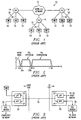
- FIG. 1 illustrates a simplified topology of the PSTN (public switched telephone network) 10.
- An inter-CO network 12 provides connections between various COs 14.
- the inter-CO network 12 uses high capacity fiber optic technology for fast, economical transfer of information between COs 14.
- the COs 14 are coupled to analog telecommunications devices, such as telephones 16 through local loops 18.
- Local loops 18 are typically twisted pair copper wire.
- the local loops carry information on the frequency spectrum between 0 and 3.4 kHz, although the twisted pair local loops 18 are capable of much higher frequency transmissions.
- a tremendous amount of capital has been used in building the local loop infrastructure, which reaches almost every home and business.
- DSL technology makes use of the available high frequency band of the local loops to transmit data at extremely high speeds.
- Figure 2 illustrates a typical spectrum allocation for a DSL modem which allows simultaneous voice band connections along with data transmission.
- the voice transmission between the analog telecommunications device 16 and the CO 14 uses the frequency band between 0 and 3.4 kHz.
- the DSL upstream band (over which data is transmitted to the CO 14) uses the frequency spectrum between 30kHz and 138 kHz.
- the DSL downstream band uses the frequency spectrum between 181 kHz and 1.1 MHz. It should be noted that these frequency spectrums are presented as an example; different DSL technologies allocate the spectrum differently.
- echo cancellation can be used such that the DSL upstream band and downstream band overlap, as is well known in the art. Echo cancellation does not, however, allow the voice band to overlap the upstream band or downstream band.
- splitters are used, as is shown in Figure 3.
- the splitters 30 use a low pass filter (LPF) 32 to pass voice band frequencies to and from the analog telecommunications devices 16 operating in the voice band (on the user side of the local loop 18) and the CO (on the CO side of the local loop) and use a high pass filter (HPF) 34 to pass the upstream and downstream frequencies to and from the DSL modems 36 and 38 on the user and CO sides of the local loop, respectively.
- LPF low pass filter
- HPF high pass filter
- a splitter is used to pass the voice band to the existing wiring and the data bands to a dedicated line for a DSL modem.
- This structure works well, but is typically not user installable.
- Another configuration maintains the existing wiring intact and each device connected to the wiring has an associated filter.
- a low pass filter can be connected between each analog telecommunications device and the wall jack and a high pass filter can be connected between the DSL modem and the wall jack such that neither device affects the frequency band associated with the other.
- Some modems have internal high pass filters.
- the configuration set out in Figures 2 and 3 provides significant advantages over standard analog telecommunications modems.
- the voice band used for standard analog communications devices such as telephones and faxes, is not affected by data communications between the DSL modems and, therefore, voice and data communications can occur simultaneously over a single physical connection (i.e., the local loop 18).
- the data connection is permanent (i.e., no dial up is necessary for connection to an Internet Service Provider).
- FIGs 4 and 5 illustrate implementations of DSL modems for the user and CO sides, respectively, which provide for simultaneous voice and data communications, while providing for full bandwidth data communications when the voice band is not being used.
- a block diagram of a user side DSL modem 36 is shown.
- the local loop 18 is connected to the DSL modem 36, typically though the internal building wiring.
- the local loop 18 will also be connected to one or more analog telecommunications devices 16 via a splitter or low pass filter to isolate the voice band signals.
- the DSL modem 36 includes programmable filter circuitry 40 and hook detection circuitry 42 coupled to the local loop 18.
- Programmable filter circuitry 40 and hook detection circuitry 42 are coupled to DSL Processing and Control circuitry 44.
- DSL Processing and Control circuitry 44 is coupled to a computer or network on the user side.
- hook detection circuitry 42 determines whether one or more of the analog telecommunications devices 16 coupled to the local loop 18 are in an off-hook state (i.e., being used). If so, a corresponding signal is output from the hook detection circuitry 42 to the DSL Processing and Control circuitry 44.
- the signal could be a simple binary status signal, such as a binary "0" which is stored in one bit of a control register, for example.
- a binary "1" could be used to represent an on-hook state.
- the local loop is in an on-hook state when all analog telecommunications devices 16 coupled to the loop are on-hook and is in an off-hook state when any analog telecommunications devices 16 coupled to the local loop is off-hook.
- Hook detection circuitry can detect whether any analog telecommunications devices 16 are off-hook through the impedance between the "tip" and "ring" lines of the local loop.
- an analog telecommunications devices 16 is on-hook, only the telephone ringer is across the tip and ring lines.
- the impedance of the ringer is such that the voltage drop across the tip and ring lines is between forty-five and forty eight volts.
- the impedance of the microphone and handset is substituted for the impedance of the ringer and the voltage across the tip and ring lines drops to approximately one to eight volts.
- the change of impedance (or voltage) across the tip and ring lines can easily be detected.
- the voice band frequencies are not being used by any device.
- the DSL modem 36 can take advantage of the additional bandwidth by using the voice band frequencies for data communications. Since attenuation is a function of distance and frequency, the voice band frequencies are the least attenuated, and therefore the most efficient at data transfer. It is estimated that addition of the voice band frequencies to the data communications bands can result in a speed increase on the order of 300 kbps which can be allocated between the upstream and downstream data streams.
- the programmable filter circuitry To implement the full spectrum communications in response to a on-hook status signal from the hook detection circuitry 42, the programmable filter circuitry must be notified, such that the filters on the transmitted and received signals are adjusted to accommodate the new upstream and downstream data bands. Further, the CO-side DSL modem 38 must be notified so that it is aware of the change in the frequency spectrums associated with the upstream and downstream bands.
- the signaling protocols used for the analog POTS will likely cause large low-frequency interference that the system must be prepared to handle.
- the hook detection circuitry can be modified to recognize the forms of interference and notify the DSL Processing and Control circuitry 44 that the interference which occurred is likely to have caused errors in the current received data.
- the DSL Processing and Control circuitry 44 can then implement a request for retransmission to the CO DSL Processing and Control module, which can resend the information that was lost.
- the user-side DSL modem 36 detects ringing pulses, it is likely that some of the analog POTS equipment will go to the off-hook state in response to the ringing signal so the modems can prepare to transition to the state where the home equipment is in the off-hook state.
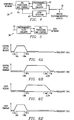
- FIG. 5 illustrates a block diagram of a CO-side DSL modem 38.
- This modem is similar in design to the user-side DSL modem, with the exception that the hook detection circuitry is not needed (or is disabled).
- the DSL Processing and Control circuitry 44 of the CO-side DSL modem 38 communicates with the DSL Processing and Control circuitry 44 of the user-side modem 36 during operation over a control channel.
- This control channel is a feature used by all DSL modems which require communication between the two modems for operation.
- the user-side DSL modem 36 provides information to the CO-side of the current on/off-hook state of the user-side analog telecommunications devices 16. When a change in on/off-hook state occurs, the CO-side acknowledges the change and the two modems arbitrate the change in the data bands.
- FIG. 6 illustrates frequency diagrams for a DSL modem pair working with the frequency bands shown in Figure 2.
- Both the CO DSL modem 38 and the user DSL modem 36 have receive and transmit filters which correspond to the frequency bands being used for data communication.
- the CO receive filter has the same filter points as the user transmit filter (both correspond to the upstream data band) and the CO transmit filter has the same filter points as the user receive filter (both correspond to the downstream data band) .
- the illustrated embodiment shows a configuration without echo cancellation; if echo cancellation was used the transmit and receive filters for both modems 36 and 38 would be overlapping.
- the frequency bands shown in Figures 2 and 6 are provided as an example, and the frequency spectrums used in an actual implementation would depend upon the DSL technology being employed.
- both modems 36 and 38 When one or more analog telecommunications devices 16 are in an off-hook state, i.e., when the voice band is being used for voice communications, both modems 36 and 38 would be in their default state shown in Figure 6. The modems 36 and 38 would continue to communicate in this state until all of the analog telecommunications devices 16 coupled to the local loop 18 were placed in an on-hook state.
- the modems 36 and 38 could transition to a higher speed configuration by using the additional, unused, voice channel. This transition could be effected automatically by the modems 36 and 38 upon recognition of the on-hook condition. Alternatively, the user could be notified of the current state and the transition would take place after confirmation.
- the DSL signal can interact with the analog telecommunications device's impedance and potentially introduce distortion in the DSL signal, particularly at the ringer frequency of 20 Hz.
- the programmable filter circuitry can be designed to avoid the very low part of the voice frequency band, with a cutoff frequency of, for example, 100 Hz.
- the modems 36 and 38 could return to the lower speed communication rate, thus returning the voice band for voice communications.
- Figure 7 illustrates frequency diagrams for the transmit and receive filters of the CO modem 38 and user modem 36 in the high-speed state.
- the voice band frequencies are allocated to the upstream data band. Accordingly, the filter points for the CO transmit filter and the user receive filter remain unchanged. The CO receive filter and the user transmit filter however now pass all the frequencies between 0 and 30 kHz, providing a significant speed in upstream speed.
- the bandwidth for downstream communications is larger than that for upstream communications, because larger files are typically downloaded to a user, rather than uploaded.
- VoIP voice over internet protocol
- video conferencing this may not be the case, and it would be preferable for the user to have the additional bandwidth illustrated in Figure 6.
- a DSP is used to implement the DSL functions described above.
- a single DSP can be used for the DSL functions and also to support analog voice channel data communications, i.e., a voice modem and/or facsimile.
- the voice channel data communications could operate simultaneously with the DSL functions (although the DSL communications would then be limited to the data band frequencies) or either function could be used separately.
- Embodiments of the present invention can be used in conjunction with a number of DSL technologies and modulation techniques.
- Both CAP (carrierless amplitude-phase) modulation and DMT (discrete multitone) modulation, along with other modulation techniques, can use the additional bandwidth afforded by an unused voice band to increase data communications speeds.
- the aspect of modifying the data bands can be used with ADSL, SDSL, RADSL, ADSL-Lite and other DSL implementations.
- While embodiments of the present invention have been discussed in connection with applying a certain DSL implementation over a larger frequency spectrum when the local loop is in an on-hook state to obtain greater data communication speeds, it should be noted that the modems could communicate using two different techniques depending upon the state of the local loop 18. Thus, when the local loop 18 was in an off-hook state, a technique which did not require the voice band frequencies would be used; when the local loop was in an on-hook state, a second technique could be used, such as HDSL, which could not be implemented while using the voice band frequencies for analog communications.
- the switching between different DSL implementations or modulation schemes would require a significant amount of setup on both the user-side and CO-side modem 36 and 38.
- hook detection circuitry is shown in the user-side modem, it could be alternatively implemented in the CO-side modem to detect off-hook conditions from the CO-side.
Landscapes
- Engineering & Computer Science (AREA)
- Computer Networks & Wireless Communication (AREA)
- Signal Processing (AREA)
- Telephonic Communication Services (AREA)
- Communication Control (AREA)
- Maintenance And Management Of Digital Transmission (AREA)
Applications Claiming Priority (2)
| Application Number | Priority Date | Filing Date | Title |
|---|---|---|---|
| US232305 | 1999-01-15 | ||
| US09/232,305 US6522730B1 (en) | 1999-01-15 | 1999-01-15 | DSL communication system with improved bandwidth |
Publications (2)
| Publication Number | Publication Date |
|---|---|
| EP1024648A2 true EP1024648A2 (de) | 2000-08-02 |
| EP1024648A3 EP1024648A3 (de) | 2009-09-09 |
Family
ID=22872602
Family Applications (1)
| Application Number | Title | Priority Date | Filing Date |
|---|---|---|---|
| EP00300242A Withdrawn EP1024648A3 (de) | 1999-01-15 | 2000-01-14 | Kommunikationssystem |
Country Status (3)
| Country | Link |
|---|---|
| US (1) | US6522730B1 (de) |
| EP (1) | EP1024648A3 (de) |
| JP (1) | JP2000216913A (de) |
Cited By (1)
| Publication number | Priority date | Publication date | Assignee | Title |
|---|---|---|---|---|
| DE10139935B4 (de) * | 2001-08-14 | 2008-06-19 | Siemens Ag | Verfahren und Vorrichtung zur Detektion von transienten Störungen in xDSL-Systemen |
Families Citing this family (45)
| Publication number | Priority date | Publication date | Assignee | Title |
|---|---|---|---|---|
| US6480510B1 (en) | 1998-07-28 | 2002-11-12 | Serconet Ltd. | Local area network of serial intelligent cells |
| WO2000044195A1 (en) * | 1999-01-20 | 2000-07-27 | Fujitsu Limited | High speed digital transmission method employing analog subscriber's loop, subscriber accommodation system used for the high speed digital transmission method, subscriber terminated side accommodation device, and accommodating station side accommodation device |
| US6690677B1 (en) | 1999-07-20 | 2004-02-10 | Serconet Ltd. | Network for telephony and data communication |
| US6549616B1 (en) | 2000-03-20 | 2003-04-15 | Serconet Ltd. | Telephone outlet for implementing a local area network over telephone lines and a local area network using such outlets |
| CA2303631A1 (en) * | 2000-03-31 | 2001-09-30 | Catena Networks Canada Inc. | A system and method for programmable spectrum management |
| IL135744A (en) * | 2000-04-18 | 2008-08-07 | Mosaid Technologies Inc | Telephone communication system over a single telephone line |
| US6842459B1 (en) | 2000-04-19 | 2005-01-11 | Serconet Ltd. | Network combining wired and non-wired segments |
| US6724871B2 (en) * | 2000-06-22 | 2004-04-20 | Smart Link Ltd. | System and method for adding multiple line capabilities to an existing CPE wiring system |
| US7047312B1 (en) * | 2000-07-26 | 2006-05-16 | Nortel Networks Limited | TCP rate control with adaptive thresholds |
| US7356605B1 (en) * | 2000-12-29 | 2008-04-08 | Cisco Technology, Inc. | System and method for controlling delivery of streaming media |
| EP1404099A4 (de) * | 2001-06-04 | 2007-03-21 | Sharp Kk | Internet-fernsprechvorrichtung und internet-fernsprechsystem |
| IL144158A (en) | 2001-07-05 | 2011-06-30 | Mosaid Technologies Inc | Socket for connecting an analog telephone to a digital communications network that carries digital voice signals |
| DE60112760T2 (de) * | 2001-09-27 | 2006-06-01 | Alcatel | Modem und Verfahren zur Parallelschaltung von Modems an einem Netzwerk |
| WO2003039150A1 (en) * | 2001-10-11 | 2003-05-08 | Serconet Ltd. | Outlet with analog signal adapter, a method for use thereof and a network using said outlet |
| US7272215B2 (en) * | 2002-05-08 | 2007-09-18 | Paradyne Corporation | Automatic rapid switching between DSL service and POTS over loaded loops |
| US20040095257A1 (en) * | 2002-08-12 | 2004-05-20 | Smartlink Ltd. | High-speed analog modem |
| US6934368B2 (en) * | 2002-08-12 | 2005-08-23 | Smartlink Ltd. | Multi-band modem |
| US7154996B2 (en) * | 2002-10-29 | 2006-12-26 | Agere Systems Inc. | Dynamic frequency passband switching in home phone-line networks |
| IL154234A (en) * | 2003-01-30 | 2010-12-30 | Mosaid Technologies Inc | Method and system for providing dc power on local telephone lines |
| IL154921A (en) * | 2003-03-13 | 2011-02-28 | Mosaid Technologies Inc | A telephone system that includes many separate sources and accessories for it |
| US6956746B2 (en) * | 2003-06-20 | 2005-10-18 | Hewlett-Packard Development Company, L.P. | Electronic system with a movable printed circuit assembly |
| US20050105602A1 (en) * | 2003-06-30 | 2005-05-19 | Miguel Peeters | System and method for extended range digital subscriber line |
| IL157787A (en) | 2003-09-07 | 2010-12-30 | Mosaid Technologies Inc | Modular outlet for data communications network |
| US20050135490A1 (en) * | 2003-12-22 | 2005-06-23 | Randy Zimler | Methods of providing communications services |
| US20060010247A1 (en) * | 2003-12-22 | 2006-01-12 | Randy Zimler | Methods for providing communications services |
| US20060133518A1 (en) * | 2003-12-22 | 2006-06-22 | Randy Zimler | Methods for providing communications services |
| IL159838A0 (en) | 2004-01-13 | 2004-06-20 | Yehuda Binder | Information device |
| IL161869A (en) * | 2004-05-06 | 2014-05-28 | Serconet Ltd | A system and method for carrying a signal originating is wired using wires |
| US20060093104A1 (en) * | 2004-10-06 | 2006-05-04 | Smartlink Ltd. | Telephone adapter with advanced features |
| US7873058B2 (en) | 2004-11-08 | 2011-01-18 | Mosaid Technologies Incorporated | Outlet with analog signal adapter, a method for use thereof and a network using said outlet |
| US20060153169A1 (en) * | 2004-12-13 | 2006-07-13 | Smartlink Ltd. | Customer premises network with PSTN and packet telephony functions |
| JP4463133B2 (ja) * | 2005-03-25 | 2010-05-12 | Necインフロンティア株式会社 | ボタン電話装置および音声通信チャネル制御方法 |
| US20070041366A1 (en) * | 2005-05-24 | 2007-02-22 | Smart Link Ltd. | Distributed conference bridge |
| US20070025338A1 (en) * | 2005-07-26 | 2007-02-01 | Smartlink Ltd.. | Software-based solutions for telephone network bridging |
| US20070116056A1 (en) * | 2005-10-12 | 2007-05-24 | The Regents Of The University Of California | Digital subscriber line access sharing method and device |
| US7813451B2 (en) * | 2006-01-11 | 2010-10-12 | Mobileaccess Networks Ltd. | Apparatus and method for frequency shifting of a wireless signal and systems using frequency shifting |
| WO2009053910A2 (en) | 2007-10-22 | 2009-04-30 | Mobileaccess Networks Ltd. | Communication system using low bandwidth wires |
| US8175649B2 (en) | 2008-06-20 | 2012-05-08 | Corning Mobileaccess Ltd | Method and system for real time control of an active antenna over a distributed antenna system |
| US8897215B2 (en) | 2009-02-08 | 2014-11-25 | Corning Optical Communications Wireless Ltd | Communication system using cables carrying ethernet signals |
| EP2429153A1 (de) | 2010-09-10 | 2012-03-14 | British Telecommunications Public Limited Company | System zur Bereitstellung von Daten- und Telefondiensten |
| EP2456189A1 (de) * | 2010-11-23 | 2012-05-23 | British Telecommunications Public Limited Company | System zur Bereitstellung von Telefon- und Datendiensten |
| WO2013142662A2 (en) | 2012-03-23 | 2013-09-26 | Corning Mobile Access Ltd. | Radio-frequency integrated circuit (rfic) chip(s) for providing distributed antenna system functionalities, and related components, systems, and methods |
| JP6323977B2 (ja) * | 2012-12-27 | 2018-05-16 | キヤノン株式会社 | 通信装置及び該装置の制御方法 |
| US10110755B2 (en) | 2013-12-31 | 2018-10-23 | British Telecommunications Public Limited Company | Method and apparatus for use in supplying power over a telephone line |
| US9184960B1 (en) | 2014-09-25 | 2015-11-10 | Corning Optical Communications Wireless Ltd | Frequency shifting a communications signal(s) in a multi-frequency distributed antenna system (DAS) to avoid or reduce frequency interference |
Family Cites Families (4)
| Publication number | Priority date | Publication date | Assignee | Title |
|---|---|---|---|---|
| US6061392A (en) * | 1996-12-17 | 2000-05-09 | Paradyne Corporation | Apparatus and method for communicating voice and data between a customer premises and a central office |
| CA2272576A1 (en) * | 1996-12-17 | 1998-06-25 | Thomas Bingel | Apparatus and method for communicating voice and data between a customer premises and a central office |
| US6151335A (en) * | 1997-12-02 | 2000-11-21 | Conexant Systems, Inc. | Modulation switching for DSL signal transmission |
| US6269154B1 (en) * | 1998-02-04 | 2001-07-31 | Texas Instruments Incorporated | Splitterless modem with integrated off-hook detector |
-
1999
- 1999-01-15 US US09/232,305 patent/US6522730B1/en not_active Expired - Lifetime
- 1999-12-28 JP JP11375451A patent/JP2000216913A/ja not_active Abandoned
-
2000
- 2000-01-14 EP EP00300242A patent/EP1024648A3/de not_active Withdrawn
Cited By (1)
| Publication number | Priority date | Publication date | Assignee | Title |
|---|---|---|---|---|
| DE10139935B4 (de) * | 2001-08-14 | 2008-06-19 | Siemens Ag | Verfahren und Vorrichtung zur Detektion von transienten Störungen in xDSL-Systemen |
Also Published As
| Publication number | Publication date |
|---|---|
| US6522730B1 (en) | 2003-02-18 |
| EP1024648A3 (de) | 2009-09-09 |
| JP2000216913A (ja) | 2000-08-04 |
Similar Documents
| Publication | Publication Date | Title |
|---|---|---|
| US6522730B1 (en) | DSL communication system with improved bandwidth | |
| US5901205A (en) | Adaptive voice and data bandwidth management system for multiple-line digital subscriber loop data communications | |
| CA2301546C (en) | Apparatus and method for concurrent voice and data transmission | |
| KR100342500B1 (ko) | 고속 데이터 서비스 및 음성 서비스를 제공하기 위한 방법 | |
| US7020266B2 (en) | Simultaneous transmission of an analog pots signal and a digital signal on a subscriber line | |
| US7233649B2 (en) | Faster modem method and apparatus | |
| EP1155564B1 (de) | An einer digitalen teilnehmerleitung (dsl) angeschlossenes modem ohne splitter | |
| US7391764B2 (en) | Method and system for combining symmetric DSL signals and voice signals | |
| US6269154B1 (en) | Splitterless modem with integrated off-hook detector | |
| US6456650B1 (en) | Splitterless modem using harmonics reduction | |
| US6647024B1 (en) | System and method for an all digital communication system with a life line | |
| WO1999049608A2 (en) | Apparatus and method for reallocating time division multiplexing voice bandwidth for data transmission | |
| Hawley | Systems considerations for the use of xDSL technology for data access | |
| US6922415B1 (en) | Apparatus and method for a non-symmetrical half-duplex DSL modem | |
| JP4272379B2 (ja) | 電話サービスを提供する方法及びシステム並びに物品 | |
| US7352803B2 (en) | Apparatus and method for communicating voice and data between a customer premises and a central office | |
| CN1489860A (zh) | 使用公用交换电话网的数字用户线的功率缩减配置 | |
| US6795548B2 (en) | Method and system for data communication | |
| KR100359476B1 (ko) | 기존 전화기를 접목한 내장형 에이디에스엘 모뎀 | |
| US7082125B1 (en) | Communication model for linecard modems | |
| US20020141428A1 (en) | Line card and method for supporting a plurality of telecommunication services | |
| US6952417B1 (en) | System and method for selectively providing data communications in an XDSL communication system | |
| KR20000011363U (ko) | 스플릿터 내장형 비대칭 디지털 가입자 라인 모뎀 | |
| WO1998038813A2 (en) | Apparatus and method for a multipoint dsl modem | |
| JP2004320470A (ja) | 通信装置 |
Legal Events
| Date | Code | Title | Description |
|---|---|---|---|
| PUAI | Public reference made under article 153(3) epc to a published international application that has entered the european phase |
Free format text: ORIGINAL CODE: 0009012 |
|
| AK | Designated contracting states |
Kind code of ref document: A2 Designated state(s): AT BE CH CY DE DK ES FI FR GB GR IE IT LI LU MC NL PT SE |
|
| AX | Request for extension of the european patent |
Free format text: AL;LT;LV;MK;RO;SI |
|
| PUAL | Search report despatched |
Free format text: ORIGINAL CODE: 0009013 |
|
| AK | Designated contracting states |
Kind code of ref document: A3 Designated state(s): AT BE CH CY DE DK ES FI FR GB GR IE IT LI LU MC NL PT SE |
|
| AX | Request for extension of the european patent |
Extension state: AL LT LV MK RO SI |
|
| RIC1 | Information provided on ipc code assigned before grant |
Ipc: H04M 11/06 20060101ALI20090803BHEP Ipc: H04M 11/00 20060101AFI20000606BHEP |
|
| AKX | Designation fees paid |
Designated state(s): AT |
|
| REG | Reference to a national code |
Ref country code: DE Ref legal event code: 8566 |
|
| STAA | Information on the status of an ep patent application or granted ep patent |
Free format text: STATUS: THE APPLICATION IS DEEMED TO BE WITHDRAWN |
|
| 18D | Application deemed to be withdrawn |
Effective date: 20100310 |