EP1024283A2 - Starter device for internal combustion engines - Google Patents
Starter device for internal combustion engines Download PDFInfo
- Publication number
- EP1024283A2 EP1024283A2 EP00100643A EP00100643A EP1024283A2 EP 1024283 A2 EP1024283 A2 EP 1024283A2 EP 00100643 A EP00100643 A EP 00100643A EP 00100643 A EP00100643 A EP 00100643A EP 1024283 A2 EP1024283 A2 EP 1024283A2
- Authority
- EP
- European Patent Office
- Prior art keywords
- locking
- starter device
- drive shaft
- locking members
- guide
- Prior art date
- Legal status (The legal status is an assumption and is not a legal conclusion. Google has not performed a legal analysis and makes no representation as to the accuracy of the status listed.)
- Withdrawn
Links
Images


Classifications
-
- F—MECHANICAL ENGINEERING; LIGHTING; HEATING; WEAPONS; BLASTING
- F02—COMBUSTION ENGINES; HOT-GAS OR COMBUSTION-PRODUCT ENGINE PLANTS
- F02N—STARTING OF COMBUSTION ENGINES; STARTING AIDS FOR SUCH ENGINES, NOT OTHERWISE PROVIDED FOR
- F02N15/00—Other power-operated starting apparatus; Component parts, details, or accessories, not provided for in, or of interest apart from groups F02N5/00 - F02N13/00
- F02N15/02—Gearing between starting-engines and started engines; Engagement or disengagement thereof
- F02N15/04—Gearing between starting-engines and started engines; Engagement or disengagement thereof the gearing including disengaging toothed gears
- F02N15/06—Gearing between starting-engines and started engines; Engagement or disengagement thereof the gearing including disengaging toothed gears the toothed gears being moved by axial displacement
- F02N15/062—Starter drives
- F02N15/065—Starter drives with blocking means
-
- F—MECHANICAL ENGINEERING; LIGHTING; HEATING; WEAPONS; BLASTING
- F02—COMBUSTION ENGINES; HOT-GAS OR COMBUSTION-PRODUCT ENGINE PLANTS
- F02N—STARTING OF COMBUSTION ENGINES; STARTING AIDS FOR SUCH ENGINES, NOT OTHERWISE PROVIDED FOR
- F02N15/00—Other power-operated starting apparatus; Component parts, details, or accessories, not provided for in, or of interest apart from groups F02N5/00 - F02N13/00
- F02N15/02—Gearing between starting-engines and started engines; Engagement or disengagement thereof
- F02N15/022—Gearing between starting-engines and started engines; Engagement or disengagement thereof the starter comprising an intermediate clutch
- F02N15/023—Gearing between starting-engines and started engines; Engagement or disengagement thereof the starter comprising an intermediate clutch of the overrunning type
Definitions
- the present invention relates to a starter device for internal combustion engines, and in particular is directed to a centrifugally actuated starter for motorcycles, motor sledges and the like, of the type described in the preamble of the claim 1.
- a starter device comprises a drive shaft directly or indirectly connected to an electric motor for starting the combustion engine.
- An assembly comprising a pinion gear and a thrust element connected one to the other by means of a unidirectional coupling device, is rotatingly and axially supported by the drive shaft to move between a retracted or disengaged position, and an advanced or engaged position in respect to a drive gear of the combustion engine.
- the thrust element is in turn coupled to the drive shaft of the starter by means of helical splines for axial movement and for driving the pinion gear to rotate.
- Locking means in the form of radially movable members actuated by a centrifugal action caused by rotation of the drive shaft, are movably supported together with the thrust element to engage with the drive shaft and an external protection cage to prevent the backward movement of the pinion gear when engaged with the drive gear of the combustion engine, until the latter has been started.
- Starter devices of the type mentioned above have in general a somewhat complex structure and can be the cause of some difficulties, mainly linked to an erratic sliding of the centrifugal locking means, caused by possible accumulation of dirt inside the normally closed space of a dome or of a casing which houses the centrifugally actuated weight members.
- a main object of the present invention is therefore to provide a starter device for internal combustion engines of simpler construction, having small overall dimensions, and constructed by few pieces and hence easy to assemble.
- a further object of the present invention is to provide a starter device, as referred above, having improved performances and a greater working reliability, and which uses the same centrifugal force acting to lock the pinion gear, to allow for an automatic ejection of the dirt which tends to accumulate into the space of the cage housing the same centrifugal locking means.
- Yet another object of the present invention is to provide a starter device as defined above, which has comparatively low industrialisation costs and whose maintenance is easy.
- a starter device for internal combustion engines, comprising:
- the locking means for the control assembly comprises first and second centrifugally actuated ring like locking members, oppositely disposed and encircling the drive shaft within a guide cage fastened to rotate with the drive shaft, and biasing means acting on said first and second locking members to move apart and disengage said locking members from the control assembly when the drive shaft is rotating below said prefixed rotational speed.
- Each of the locking elements preferably has a weight portion at one side, having an arched configuration which is arranged around the drive shaft.
- each locking element has a C shaped configuration comprising an arched weight portion on one side, joining to a stop tooth on the opposite side by means of an intermediate connection arm which extends from one end of the same weight portion of the locking element of the starter device.
- each locking element has an annular configuration comprising on one side a weight portion connected to a stop tooth by two intermediate arms which extend from the ends of the above mentioned weight portion on both sides of the drive shaft of the starter device.
- the starter device denoted overall by reference 10, comprises a drive shaft 11 which can constitute for example an extension of a power shaft of an electric starter motor, not shown, or can be separated and connected to the power shaft of the electric motor by means of an intermediate gear 12 fastened to the rear end of the drive shaft 11.
- the starter device 10 also comprises a movable control assembly 13, for the transmission of the rotational forces generated by the electric starter motor, which is designed to engage with a drive gear 15 of a power shaft of a combustion engine; reference 16 indicates a centrifugally actuated locking unit to stop the control assembly 13 in the engaged condition with the gear 15, to prevent backward movement at a rotational speed of the drive shaft 11 above a prefixed value.
- the assembly 13 comprises a pinion gear 17 designed to engage the teeth of the gear 15, appropriately supported to freely rotate and to axially slide along the shaft 11.
- the pinion gear 17 is in turn supported on the shaft 11 by means of a bush 18 and is rotatably connected to a thrust element 19 by means of a unidirectional roller clutch 20, for example an intermediate freewheel coupling which allows the thrust element 19 to rotate the pinion gear 17 in one direction and to move towards the gear 15, letting the same thrust element 19 to freely rotate in an opposite direction after completion of the starting of the internal combustion engine whereto the starter device is connected.
- a unidirectional roller clutch 20 for example an intermediate freewheel coupling which allows the thrust element 19 to rotate the pinion gear 17 in one direction and to move towards the gear 15, letting the same thrust element 19 to freely rotate in an opposite direction after completion of the starting of the internal combustion engine whereto the starter device is connected.
- the axial movement of the thrust element 19 and its rotation by the shaft 11 is enabled by means of a tubular extension 19' of the thrust element 19 having inner splines meshing with splines 21 of the shaft 11 which extends for a predetermined length.
- the starter device 10 comprises a centrifugally-actuated locking unit 16 to restrain the control assembly 13 for the transmission of force in the advanced condition of Figure 2, so as to prevent its backward sliding and disengagement of the pinion gear 17 from the gear 15 during the starting phase of the internal combustion engine.
- the locking unit 16 is fastened to the drive shaft 11 against the gear 12 to rotate with the same; the locking unit 16 is therefore structurally and operatively separate from the control assembly 13 which can therefore freely slide and rotate on the shaft 11, and in relation to the same locking unit 16.
- the movable assembly 13 is extremely simplified from the constructional viewpoint, having extremely small dimensions and reduced weight in that, unlike previously known starter devices, the locking unit 16 now is no longer structurally and functionally connected thereto. Said locking unit 16 can therefore be constructed in a structurally independent manner, with reduced overall dimensions and with improved features as regards its functional reliability.
- the locking unit 16 comprises a guide cage 25 for housing a first locking element 26 and a second locking element 27, which are substantially coplanary arranged to allow their free radial sliding movement inside the housing cage 25, between a contracted condition, shown in Figures 1 and 6 in which they allow the sliding of the assembly 13 on the shaft 11, and an expanded condition shown in Figures 2 and 7 in which they lock the backward sliding of the thrust element 19, maintaining guided and self-aligned conditions for the same locking elements during their radial movements in respect to the shaft 11.
- References 28 and 29 in the various figures also denote two biasing springs inside the cage 25, which radially act to thrust and maintain the two locking members 26 and 27 in their contracted or advanced condition of Figure 6, when they are not subjected to the action of a centrifugal force generated by the rotation of the shaft 11 above a prefixed rotational speed.
- the two locking members 26 and 27 are wholly identical one to the other in that they are arranged in an opposite condition, overturned and rotated through 180° one against the other, inside the housing cage. Therefore, with reference to Figures 4 to 7, a description will now be given of the shaped and general features of only one of them, for example the locking member 26.
- the locking member 26 has a general C-shaped configuration defined on one side by a weight portion 30 having an arched shape.
- the weight portion 30 extends on one side with a flat arm 31, of relatively small thickness, provided on one face with a tooth 32 at the end opposite the weight 30, to form a shoulder facing the end edge of an extension 19' of the thrust element 19 for stopping the control assembly 13 in the advanced condition, shown in Figure 2.
- the tooth 32 has a flat tab 33 which radially extends outwards from the arm 31 in a diametrically opposed position to a slot 34 having flat guide surfaces for the tab 33 of the other locking member 25.
- Figures 4 and 5 show a perspective view on one side and respectively a perspective view on the opposite side of the locking member 26, and at the same time represent the arrangement that the two locking members 26 and 27 assume in their superimposed condition inside the housing cage. This condition is shown in the following Figures 6 and 7.
- the arched arm 31 is provided flush to the side face of the locking member 26 which is opposite to the slot 34, from the same slot 34 and along the inner edge of weight portion 30; furthermore one end of the weight portion 30 and arm 31 of each locking member have inner and respectively outer flat surfaces parallely extending to a radial direction and slidingly engaging with corresponding flat surfaces of the second locking member.
- each locking member 26, 27 in addition to supplying a guide and self-centring action with the guide groove 34 of the other locking member, also performs a stop function in a radial direction, against an inner wall of the housing cage, to maintain the two locking members in the retracted condition of Figures 1 and 6 where they define a circular hole for passage of the shaft 11 and of the tubular hub 19' of the thrust element 19, having inside helical splines suitable for engaging with corresponding helical splines 21 of the drive shaft 11.
- reference 35 denotes a seat for housing the biasing spring 28, 29, while reference 36 denotes a recess suitable for housing the stop tooth 32 of the facing locking member in the contracted condition of Figure 6.
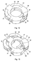
- FIGS. 8 and 9 of the accompanying drawings show a cross-section view of the locking unit 16 and a perspective view of the cage 25 for housing the two centrifugal members 26 and 27 for locking backward sliding of the thrust element 19 and of the pinion gear 17.
- the cage 25 can be manufactured from appropriately cut and shaped metal sheet, which is bent to define an open cage on both sides, to allow the ejection of any dirt or particles, exploiting the effect of the same centrifugal force generated by its rotation. If dirt accumulates inside the cage, it could hinder sliding of the two centrifugal locking members, especially at the beginning of start-up or at low rotational speeds of the drive shaft 11.
- the cage 25 is manufactured from a metal sheet blank suitably shaped and folded to define an open cage 25 having substantially a square shape.
- the cage 25 comprises a rear wall 40 and a front wall 41, intended to face towards the control assembly 13; the walls 40 and 41 are parallely arranged and appropriately spaced apart by two side walls 42 which extend in a plane, parallel to the sliding axis of the two locking members 26 and 27.
- the remaining two cross sides of the cage 25 are open outwards with the exception of a central tongue 43, designed to define a stop surface for the two locking members 26 and 27, both in the contracted condition of Figure 6 and in the expanded condition of Figure 7, as explained hereinunder.
- the front wall 41 of the cage 25 has a wide circular hole 44 having a diameter larger than the outer diameter of the tubular hub 19' of the thrust element 19, to allow the passage thereof, while the rear wall 40 has in turn a hole 45 with small diameter, substantially corresponding to the diameter of the shaft 11, to form a resting surface against which an annular shoulder of the shaft 11 rests, by means of which the cage 25 is fastened against the gear 12.
- the locking unit 16 for the thrust element 19 is provided with means for guiding and self-centring the locking members 26, 27, as well as stop means which act, against the thrust exerted by the springs 28 and 29, to maintain the two locking members 26 and 27 in their retracted condition of Figures 1 and 6 radially spaced and disengaged by the hub 19' of the thrust element 19, and by the helical splines 21 of the drive shaft 11.
- Said stop means in the disengaged condition of Figure 1, are substantially formed by the two radial tabs 33 which come into contact with the side tongues 43 of the housing cage 25, while in the condition of Figure 2 they are defined by the same weight portions 30 of each locking member, which always come into contact with the tongues 43 indicated above.
- the teeth 32 with the respective housing apertures 36 also contribute to provide a self-centring function which in this way is performed simultaneously in two diametrically opposed positions, always allowing perfect alignment of the two locking members in any of their positions.
- the working mode of the starter device is the following: during the starting of the internal combustion engine, the electric motor of the starter causes rotation of the drive shaft 11 which in turn, through the helical splines 21, drives rotation of the thrust element 19.
- the latter due to the inertia phenomenon, tends to move forwards along the shaft 11, pushing the pinion gear 17 forwards until it engages with the gear 15, in the condition shown in Figure 2.
- This forward movement of the thrust element thus allows coupling of the pinion 17 with the gear 15 and the consequent driving rotation of the same for starting of the internal combustion engine.
- the internal combustion engine has in general a discontinuous rotation motion which, on going beyond the dead centre of the cylinder or cylinders of the engine, will tend to considerably increase causing, by reaction, a backward movement of the thrust element 19 and a possible disengaging of the pinion 17 from the gear 15.
- the two locking members 26 and 27 guide themselves, remaining self-centred, and in this way the operational reliability of the entire starter device improves. Moreover, the two locking members 26 and 27 stop against the tongues 43 of the housing cage 25, which limit their outward radial movement, preventing said members from interfering with the helical splines 21 of the drive shaft 11. Moreover, in this condition, the two teeth 32 offer a large stop surface for the end of the tubular hub 19' of the thrust element 19, whereon most of the axial stresses inside the same device can discharge.
- FIGS. 10 to 13 of the drawings show a second possible embodiment of the two locking members 26 and 27.
- the solution of Figures 4 - 7 is preferable in that it allows provision for the use of a centrifugal mass 30 of greater weight, on a par with the size, and therefore an increase in the sensitivity of the centrifugal locking unit which in this way shows a more decided and more rapid action even at the low rotational speeds of the drive shaft 11.
- a starter device comprising a locking system with locking members characterised by a specific configuration and arrangement of the weight and stop parts such as to ensure their constant self-alignment and rapid intervention of the starter device even at low rotational speeds of the engine.
- the housing of the locking members in a cage open at the sides in addition to simplifying the whole starter device in constructional terms, makes it more reliable in that any dirt which accumulates inside the cage can easily be ejected by the centrifugal force generated of each starting of the engine.
Abstract
Description
- The present invention relates to a starter device for internal combustion engines, and in particular is directed to a centrifugally actuated starter for motorcycles, motor sledges and the like, of the type described in the preamble of the claim 1.
- Starter devices for motorcycles and the like are known for example from US-A-4,325,265 and from EP-A-O 333 669 which constitute the prior art closest to the present invention. In general, a starter device comprises a drive shaft directly or indirectly connected to an electric motor for starting the combustion engine. An assembly comprising a pinion gear and a thrust element connected one to the other by means of a unidirectional coupling device, is rotatingly and axially supported by the drive shaft to move between a retracted or disengaged position, and an advanced or engaged position in respect to a drive gear of the combustion engine.
- The thrust element is in turn coupled to the drive shaft of the starter by means of helical splines for axial movement and for driving the pinion gear to rotate. Locking means in the form of radially movable members actuated by a centrifugal action caused by rotation of the drive shaft, are movably supported together with the thrust element to engage with the drive shaft and an external protection cage to prevent the backward movement of the pinion gear when engaged with the drive gear of the combustion engine, until the latter has been started.
- Starter devices of the type mentioned above have in general a somewhat complex structure and can be the cause of some difficulties, mainly linked to an erratic sliding of the centrifugal locking means, caused by possible accumulation of dirt inside the normally closed space of a dome or of a casing which houses the centrifugally actuated weight members.
- Moreover, in the motorcycle sector or in related fields where the saving of space is generally highly critical, these starter devices can at times be too bulky and difficult to apply.
- Furthermore it is necessary to ensure starting of an engine even in particularly critical conditions, for example with the battery down, at cold condition of the engine, or in particular weather conditions wherein rapid coupling of the pinion gear with the drive gear of the engine is required, and a more reliable as well as a more emphatic locking action of the same pinion, even at low rotational speeds.
- A main object of the present invention is therefore to provide a starter device for internal combustion engines of simpler construction, having small overall dimensions, and constructed by few pieces and hence easy to assemble.
- A further object of the present invention is to provide a starter device, as referred above, having improved performances and a greater working reliability, and which uses the same centrifugal force acting to lock the pinion gear, to allow for an automatic ejection of the dirt which tends to accumulate into the space of the cage housing the same centrifugal locking means.
- Yet another object of the present invention is to provide a starter device as defined above, which has comparatively low industrialisation costs and whose maintenance is easy.
- The above objects can be achieved by means of a starter device for internal combustion engines having the features of claim 1.
- In particular, according to the present invention, a starter device has been provided for internal combustion engines, comprising:
- a drive shaft connected to an electric starting motor for the engine;
- a pinion gear provided to freely rotate and axially move on the drive shaft, to engage and disengage with a drive gear connected to the power shaft of the engine;
- a thrust element for the pinion gear, coupled to the drive shaft by helical splines;
- a unidirectional roller clutch provided between the pinion gear and said thrust element; and
- centrifugally actuated locking means rearwardly positioned in respect to the thrust element to axially lock the thrust element preventing the same from backward movement in the engaged condition of the pinion gear with the drive gear above a prefixed rotational speed of the power shaft of the engine, characterised in that:
- the pinion gear, the thrust element and the intermediate roller clutch are provided in the form of a control assembly rotatably supported and axially movable on the drive shaft; and in that
- said centrifugally actuated locking means comprises first and second radially movable locking members and guide means defining a locking unit axially fastened to rotate with the drive shaft.
-
- More particularly, the locking means for the control assembly comprises first and second centrifugally actuated ring like locking members, oppositely disposed and encircling the drive shaft within a guide cage fastened to rotate with the drive shaft, and biasing means acting on said first and second locking members to move apart and disengage said locking members from the control assembly when the drive shaft is rotating below said prefixed rotational speed.
- Each of the locking elements preferably has a weight portion at one side, having an arched configuration which is arranged around the drive shaft.
- According to a first embodiment, each locking element has a C shaped configuration comprising an arched weight portion on one side, joining to a stop tooth on the opposite side by means of an intermediate connection arm which extends from one end of the same weight portion of the locking element of the starter device.
- According to another embodiment of the invention, each locking element has an annular configuration comprising on one side a weight portion connected to a stop tooth by two intermediate arms which extend from the ends of the above mentioned weight portion on both sides of the drive shaft of the starter device.
- These and further features of the starter device according to the invention will be made clearer by the following description, with reference to the accompanying drawings, in which:
- Fig. 1 shows a longitudinal sectional view of the starter device, in a disengaged condition;
- Fig. 2 shows a longitudinal sectional view of the same starter device, in an engaged condition;
- Fig. 3 is an exploded view showing the component parts of the starter device of figure 1;
- Fig. 4 shows a perspective view, from one side of a first embodiment of a locking element for the starter device of Figure 1;
- Fig. 5 shows a perspective view, from the opposite side, of the locking element of Figure 4;
- Fig. 6 shows a perspective view of locking elements according to Figures 4 and 5, in the unlocked condition of Figure 1;
- Fig. 7 shows a perspective view of the locking elements of Figures 4 and 5 in the locking condition of Figure 2;
- Fig. 8 shows an enlarged cross-sectional view of the centrifugal locking unit for the starter device of Figure 1;
- Fig. 9 shows a perspective view of the locking unit of Figure 8;
- Figs. 10 to 13 show perspective views similar to those of Figures 4 to 7, for a second embodiment of the centrifugal locking elements of the invention.
-
- With reference to Figures 1 to 9 we will describe a first embodiment of the starter device according to the invention, and its operation mode.
- The starter device, denoted overall by
reference 10, comprises adrive shaft 11 which can constitute for example an extension of a power shaft of an electric starter motor, not shown, or can be separated and connected to the power shaft of the electric motor by means of anintermediate gear 12 fastened to the rear end of thedrive shaft 11. - The
starter device 10 also comprises amovable control assembly 13, for the transmission of the rotational forces generated by the electric starter motor, which is designed to engage with adrive gear 15 of a power shaft of a combustion engine;reference 16 indicates a centrifugally actuated locking unit to stop thecontrol assembly 13 in the engaged condition with thegear 15, to prevent backward movement at a rotational speed of thedrive shaft 11 above a prefixed value. - In particular, the
assembly 13 comprises apinion gear 17 designed to engage the teeth of thegear 15, appropriately supported to freely rotate and to axially slide along theshaft 11. - The
pinion gear 17 is in turn supported on theshaft 11 by means of abush 18 and is rotatably connected to athrust element 19 by means of aunidirectional roller clutch 20, for example an intermediate freewheel coupling which allows thethrust element 19 to rotate thepinion gear 17 in one direction and to move towards thegear 15, letting thesame thrust element 19 to freely rotate in an opposite direction after completion of the starting of the internal combustion engine whereto the starter device is connected. - The axial movement of the
thrust element 19 and its rotation by theshaft 11 is enabled by means of a tubular extension 19' of thethrust element 19 having inner splines meshing withsplines 21 of theshaft 11 which extends for a predetermined length. - A
biasing spring 22, restrained by acup element 23, acts on the side of thepinion gear 17 which is opposite to thethrust element 19, to normally maintain thepinion gear 17 disengaged from thegear 15, as shown in Figure 1. - As previously referred to, the
starter device 10 comprises a centrifugally-actuatedlocking unit 16 to restrain thecontrol assembly 13 for the transmission of force in the advanced condition of Figure 2, so as to prevent its backward sliding and disengagement of thepinion gear 17 from thegear 15 during the starting phase of the internal combustion engine. - As can be seen in Figures 1, 2 and 3, the
locking unit 16 is fastened to thedrive shaft 11 against thegear 12 to rotate with the same; thelocking unit 16 is therefore structurally and operatively separate from thecontrol assembly 13 which can therefore freely slide and rotate on theshaft 11, and in relation to thesame locking unit 16. - In this way the
movable assembly 13 is extremely simplified from the constructional viewpoint, having extremely small dimensions and reduced weight in that, unlike previously known starter devices, thelocking unit 16 now is no longer structurally and functionally connected thereto. Saidlocking unit 16 can therefore be constructed in a structurally independent manner, with reduced overall dimensions and with improved features as regards its functional reliability. - The structural and functional independence of the
assembly 13 for the transmission of force, from thelocking unit 16, not only enables the whole starter device to be simplified, but also allows a self-cleaning of the locking device, with improved self-balancing conditions for the centrifugal weights. - With reference to the various figures and in particular to Figures 4 to 9, we will describe now a first embodiment of the
locking unit 16 and of the related centrifugal members which act directly on thethrust element 19 to prevent backward movement thereof in the engaged condition of the device shown in Figure 2. - The
locking unit 16 comprises aguide cage 25 for housing afirst locking element 26 and asecond locking element 27, which are substantially coplanary arranged to allow their free radial sliding movement inside thehousing cage 25, between a contracted condition, shown in Figures 1 and 6 in which they allow the sliding of theassembly 13 on theshaft 11, and an expanded condition shown in Figures 2 and 7 in which they lock the backward sliding of thethrust element 19, maintaining guided and self-aligned conditions for the same locking elements during their radial movements in respect to theshaft 11. -
References cage 25, which radially act to thrust and maintain the twolocking members shaft 11 above a prefixed rotational speed. - The two
locking members locking member 26. - As shown, the
locking member 26 has a general C-shaped configuration defined on one side by aweight portion 30 having an arched shape. - The
weight portion 30 extends on one side with aflat arm 31, of relatively small thickness, provided on one face with atooth 32 at the end opposite theweight 30, to form a shoulder facing the end edge of an extension 19' of thethrust element 19 for stopping thecontrol assembly 13 in the advanced condition, shown in Figure 2. Thetooth 32 has aflat tab 33 which radially extends outwards from thearm 31 in a diametrically opposed position to aslot 34 having flat guide surfaces for thetab 33 of theother locking member 25. - Figures 4 and 5 show a perspective view on one side and respectively a perspective view on the opposite side of the
locking member 26, and at the same time represent the arrangement that the twolocking members - From figures 4 and 5 it can be seen that the
arched arm 31 is provided flush to the side face of thelocking member 26 which is opposite to theslot 34, from thesame slot 34 and along the inner edge ofweight portion 30; furthermore one end of theweight portion 30 andarm 31 of each locking member have inner and respectively outer flat surfaces parallely extending to a radial direction and slidingly engaging with corresponding flat surfaces of the second locking member. - From the same figures it can be also seen that the
tab 33 and theslot 34 of each thrust element, finding themselves in diametrically opposed positions, in addition to a guide action also perform a self-centring action for the two locking members during their movement. - The
tab 33 of each lockingmember guide groove 34 of the other locking member, also performs a stop function in a radial direction, against an inner wall of the housing cage, to maintain the two locking members in the retracted condition of Figures 1 and 6 where they define a circular hole for passage of theshaft 11 and of the tubular hub 19' of thethrust element 19, having inside helical splines suitable for engaging with correspondinghelical splines 21 of thedrive shaft 11. - Finally
reference 35 denotes a seat for housing the biasingspring reference 36 denotes a recess suitable for housing thestop tooth 32 of the facing locking member in the contracted condition of Figure 6. - Figures 8 and 9 of the accompanying drawings show a cross-section view of the locking
unit 16 and a perspective view of thecage 25 for housing the twocentrifugal members thrust element 19 and of thepinion gear 17. - More particularly, as shown in Figure 9, the
cage 25 can be manufactured from appropriately cut and shaped metal sheet, which is bent to define an open cage on both sides, to allow the ejection of any dirt or particles, exploiting the effect of the same centrifugal force generated by its rotation. If dirt accumulates inside the cage, it could hinder sliding of the two centrifugal locking members, especially at the beginning of start-up or at low rotational speeds of thedrive shaft 11. - Therefore, as shown in Figure 8, the
cage 25 is manufactured from a metal sheet blank suitably shaped and folded to define anopen cage 25 having substantially a square shape. Thecage 25 comprises arear wall 40 and afront wall 41, intended to face towards thecontrol assembly 13; thewalls side walls 42 which extend in a plane, parallel to the sliding axis of the two lockingmembers - The remaining two cross sides of the
cage 25 are open outwards with the exception of acentral tongue 43, designed to define a stop surface for the two lockingmembers - The
front wall 41 of thecage 25 has a widecircular hole 44 having a diameter larger than the outer diameter of the tubular hub 19' of thethrust element 19, to allow the passage thereof, while therear wall 40 has in turn ahole 45 with small diameter, substantially corresponding to the diameter of theshaft 11, to form a resting surface against which an annular shoulder of theshaft 11 rests, by means of which thecage 25 is fastened against thegear 12. - As referred previously, the locking
unit 16 for thethrust element 19 is provided with means for guiding and self-centring the lockingmembers springs members thrust element 19, and by thehelical splines 21 of thedrive shaft 11. - Said stop means, in the disengaged condition of Figure 1, are substantially formed by the two
radial tabs 33 which come into contact with theside tongues 43 of thehousing cage 25, while in the condition of Figure 2 they are defined by thesame weight portions 30 of each locking member, which always come into contact with thetongues 43 indicated above. - In addition to the
tabs 33 with theguide grooves 34, theteeth 32 with therespective housing apertures 36 also contribute to provide a self-centring function which in this way is performed simultaneously in two diametrically opposed positions, always allowing perfect alignment of the two locking members in any of their positions. - The working mode of the starter device according to the invention is the following: during the starting of the internal combustion engine, the electric motor of the starter causes rotation of the
drive shaft 11 which in turn, through thehelical splines 21, drives rotation of thethrust element 19. The latter, due to the inertia phenomenon, tends to move forwards along theshaft 11, pushing thepinion gear 17 forwards until it engages with thegear 15, in the condition shown in Figure 2. - This forward movement of the thrust element thus allows coupling of the
pinion 17 with thegear 15 and the consequent driving rotation of the same for starting of the internal combustion engine. During the starting step, the internal combustion engine has in general a discontinuous rotation motion which, on going beyond the dead centre of the cylinder or cylinders of the engine, will tend to considerably increase causing, by reaction, a backward movement of thethrust element 19 and a possible disengaging of thepinion 17 from thegear 15. However, during starting, as soon as theshaft 11 reaches a prefixed rotational speed, the two lockingmembers shaft 11, arranging themselves in the expanded condition of Figures 2 and 7 in which the twoteeth 32 are positioned at the rear end of the hub 19' of thethrust element 19, or engage the latter, preventing it from moving backwards and from causing disengagement of thepinion gear 17 from thegear 15. - During this outward radial movement, the two locking
members members tongues 43 of thehousing cage 25, which limit their outward radial movement, preventing said members from interfering with thehelical splines 21 of thedrive shaft 11. Moreover, in this condition, the twoteeth 32 offer a large stop surface for the end of the tubular hub 19' of thethrust element 19, whereon most of the axial stresses inside the same device can discharge. - When the starting step of the internal combustion engine has been completed, and the electric motor of the starter device has been disconnected by the electrical power source, the rotational motion of the
shaft 11 stops. In absence of centrifugal forces on the two lockingmembers springs thrust element 19. In this way thepinion gear 17 is allowed to move backwards under the thrust of thespring 22, and to return to the disengaged condition shown in Figure 1. - Figures 10 to 13 of the drawings show a second possible embodiment of the two locking
members - The locking members of Figures 10 - 13 differ from those of Figures 4 - 7 due to their ring configuration, in that the
weight portion 30, of each locking member is now connected to thetooth 32 by means of twoside arms 31. Therefore, in Figures 10 to 13, the same reference numbers of figures 4-7 have been used to indicate similar or equivalent parts. - Although both solutions give good results, the solution of Figures 4 - 7 is preferable in that it allows provision for the use of a
centrifugal mass 30 of greater weight, on a par with the size, and therefore an increase in the sensitivity of the centrifugal locking unit which in this way shows a more decided and more rapid action even at the low rotational speeds of thedrive shaft 11. - From what has been said and shown in the accompanying drawings it will be clear that a starter device has been provided, comprising a locking system with locking members characterised by a specific configuration and arrangement of the weight and stop parts such as to ensure their constant self-alignment and rapid intervention of the starter device even at low rotational speeds of the engine. Moreover, the housing of the locking members in a cage open at the sides, in addition to simplifying the whole starter device in constructional terms, makes it more reliable in that any dirt which accumulates inside the cage can easily be ejected by the centrifugal force generated of each starting of the engine.
- Therefore, what has been said and shown in respect to the accompanying drawings, has been given purely by way of a non-limiting example and other changes or variants may be made to the various parts of the entire starter device, without departing from the general principles of the invention.
Claims (14)
- A starter device (10) for an internal combustion engine, comprising:a drive shaft (11) connected to an electric starting motor for the engine;a pinion gear (17) provided to freely rotate and axially move on the drive shaft (11), to engage and disengage with a drive gear (15) connected to the power shaft of the engine;a thrust element (19) for the pinion gear (17), coupled to the drive shaft (11) by helical splines (21);a unidirectional roller clutch (20) provided between the pinion gear (17) and said thrust element (19); andcentrifugally actuated locking means (26, 27) rearwardly positioned to the thrust element (19) to axially lock the thrust element (19) preventing the same from backward movement in the engaged condition of the pinion gear (17) with the drive gear (15) above a prefixed rotational speed of the power shaft of the engine, characterised in that:the pinion gear (17), the thrust element (19) and the intermediate roller clutch (20) are provided in the form of a control assembly (13) rotatably supported and axially movable on the drive shaft (11); and in thatsaid centrifugally actuated locking means comprises first and second radially movable locking members (26, 27) and guide means defining a locking unit (16) axially fastened to rotate with the drive shaft (11).
- The starter device of claim 1, characterised in that the locking means for the control assembly comprises first (26) and second (27) centrifugally actuated and face to face arranged ring-like locking members (26, 27) encircling the drive shaft (11) within a guide cage (25) fastened to rotate with the same drive shaft (11), and biasing means (28, 29) to move apart and disengage said first and second locking members (26, 27) from the control assembly (13) when the drive shaft (11) is rotating below said prefixed rotational speed.
- The starter device according to claim 2, characterised in that the guide cage (25) for the locking members (26, 27) is provided with peripheral open side (40).
- The starter device according to claim 3, characterised in that said guide cage (25) comprises spaced apart front and rear flat walls (40, 41) parallely arranged and joined each other by flat side walls (42) parallely extending to a radial direction to provide guiding surfaces for the centrifugal locking members (26, 27).
- The starter device according to claim 4, characterised in that said guide cage (25) comprises stop means (43) for the locking members (26, 27) at its peripheral open sides.
- The starter device according to claim 5, characterised in that said stop means comprises a tongue member (43) which extend between the edges of the front and rear walls (40, 41) of the guide cage (25).
- The starter device of claim 2, characterised in that each locking member (26, 27) comprises a weight portion (30) at one side, having an arched configuration.
- The starter device according to claims 1 and 2, characterised in that said locking unit (16) comprises guide and self-centring means (33, 34) in radially opposite positions for the locking members (26, 27) of said locking unit (16).
- The starter device according to claim 8, characterised in that said guide and self-centring means comprise a radially extending guide tab (32).
- The starter device according to claim 2, characterised in that the guide cage (25) is provided with flat guide walls (42) for the locking members (26, 27), radially extending on peripheral sides.
- The starter device according to claim 10, characterised in that the guide cage (25) further comprises stop tabs (43) for the locking members (26, 27) at opposite peripheral sides.
- The starter device according to claim 2, characterised in that each locking member (26, 27) has a C shaped configuration comprising an arched weight portion (30) on one side edge, a tooth member (32) on the opposite side edge and an intermediate arch-shaped connection arm (31) coplanary extending to a side face.
- The starter device according to claim 2, characterised in that each locking member (26, 27) has an annular configuration comprising an arched weight portion (30) on one side edge, a tooth member (32) on the opposite side edge, and an arch-shaped connection arms (31) coplanary extending to a side face.
- The starter device according to claim 12 or 13, characterised in that each connection arm (31) is coplanary extending from and along an inner edge of the arch-shaped weight portion (30) of the locking members (26, 27).
Applications Claiming Priority (2)
| Application Number | Priority Date | Filing Date | Title |
|---|---|---|---|
| ITMI990151 | 1999-01-27 | ||
| ITMI990151 IT1307647B1 (en) | 1999-01-27 | 1999-01-27 | STARTING DEVICE FOR INTERNAL COMBUSTION ENGINES |
Publications (2)
| Publication Number | Publication Date |
|---|---|
| EP1024283A2 true EP1024283A2 (en) | 2000-08-02 |
| EP1024283A3 EP1024283A3 (en) | 2002-08-07 |
Family
ID=11381643
Family Applications (1)
| Application Number | Title | Priority Date | Filing Date |
|---|---|---|---|
| EP00100643A Withdrawn EP1024283A3 (en) | 1999-01-27 | 2000-01-13 | Starter device for internal combustion engines |
Country Status (2)
| Country | Link |
|---|---|
| EP (1) | EP1024283A3 (en) |
| IT (1) | IT1307647B1 (en) |
Cited By (4)
| Publication number | Priority date | Publication date | Assignee | Title |
|---|---|---|---|---|
| EP1236890A3 (en) * | 2001-03-02 | 2004-03-17 | Robert Bosch Gmbh | Inertia gear drive starter |
| FR2920837A1 (en) * | 2007-09-10 | 2009-03-13 | Valeo Equip Electr Moteur | Electrical rotating machine i.e. starter, for motor vehicle, has shaft including ribbed portion that has dents and hollows, where width of each dent, in plane perpendicular to axis of machine, is lower than width of each hollow |
| CN109185003A (en) * | 2018-09-29 | 2019-01-11 | 力帆实业(集团)股份有限公司 | The spiral big dual gear structure of motorcycle engine |
| CN112049747A (en) * | 2020-08-25 | 2020-12-08 | 广东隆鑫机车有限公司 | Ball centrifugal gear assembly, duplicate gear and engine |
Citations (3)
| Publication number | Priority date | Publication date | Assignee | Title |
|---|---|---|---|---|
| GB567440A (en) * | 1942-07-15 | 1945-02-14 | Bendix Aviat Corp | Improvement in engine starter drive |
| US4325265A (en) * | 1979-03-02 | 1982-04-20 | Honda Giken Kogyo Kabushiki Kaisha | Starter device for internal combustion engine |
| EP0333669A1 (en) * | 1988-03-18 | 1989-09-20 | Efel S.P.A. | A starter for internal combustion engines |
-
1999
- 1999-01-27 IT ITMI990151 patent/IT1307647B1/en active
-
2000
- 2000-01-13 EP EP00100643A patent/EP1024283A3/en not_active Withdrawn
Patent Citations (3)
| Publication number | Priority date | Publication date | Assignee | Title |
|---|---|---|---|---|
| GB567440A (en) * | 1942-07-15 | 1945-02-14 | Bendix Aviat Corp | Improvement in engine starter drive |
| US4325265A (en) * | 1979-03-02 | 1982-04-20 | Honda Giken Kogyo Kabushiki Kaisha | Starter device for internal combustion engine |
| EP0333669A1 (en) * | 1988-03-18 | 1989-09-20 | Efel S.P.A. | A starter for internal combustion engines |
Cited By (5)
| Publication number | Priority date | Publication date | Assignee | Title |
|---|---|---|---|---|
| EP1236890A3 (en) * | 2001-03-02 | 2004-03-17 | Robert Bosch Gmbh | Inertia gear drive starter |
| FR2920837A1 (en) * | 2007-09-10 | 2009-03-13 | Valeo Equip Electr Moteur | Electrical rotating machine i.e. starter, for motor vehicle, has shaft including ribbed portion that has dents and hollows, where width of each dent, in plane perpendicular to axis of machine, is lower than width of each hollow |
| CN109185003A (en) * | 2018-09-29 | 2019-01-11 | 力帆实业(集团)股份有限公司 | The spiral big dual gear structure of motorcycle engine |
| CN112049747A (en) * | 2020-08-25 | 2020-12-08 | 广东隆鑫机车有限公司 | Ball centrifugal gear assembly, duplicate gear and engine |
| CN112049747B (en) * | 2020-08-25 | 2022-06-24 | 广东隆鑫机车有限公司 | Ball centrifugal gear assembly, duplicate gear and engine |
Also Published As
| Publication number | Publication date |
|---|---|
| IT1307647B1 (en) | 2001-11-14 |
| EP1024283A3 (en) | 2002-08-07 |
| ITMI990151A1 (en) | 2000-07-27 |
Similar Documents
| Publication | Publication Date | Title |
|---|---|---|
| JP3815446B2 (en) | Starter | |
| EP0702148B1 (en) | Starter | |
| US20090255502A1 (en) | Starter System for Engine | |
| US4304140A (en) | Starter | |
| JP3603508B2 (en) | Starter | |
| US6633099B2 (en) | Engagement and disengagement mechanism for a coaxial starter motor assembly | |
| EP0649984B1 (en) | Starter with epicycle reduction gear | |
| CA2038749C (en) | Engine starter gearing | |
| EP1253315B1 (en) | Starters for internal combustion engine | |
| EP1024283A2 (en) | Starter device for internal combustion engines | |
| EP0482628B1 (en) | Intermediate gear type starter | |
| US4777836A (en) | Engine starter gearing | |
| US4627299A (en) | Engine starter gearing | |
| JPH01203655A (en) | Starter gear device for engine | |
| EP0819847B1 (en) | Starter with improved pinion drive and return structure | |
| JPH08326640A (en) | Starter | |
| EP0935067B1 (en) | Starter with pinion rotation restricting member | |
| US7721613B2 (en) | Method of mounting a retaining ring on an electric starter shaft comprising a starter drive assembly and corresponding starter | |
| JP3644092B2 (en) | Starter | |
| JPS6256348B2 (en) | ||
| AU685304B2 (en) | Engine starter gearing having improved grease retention | |
| JPH07293408A (en) | Electric starting motor having intermediate gear | |
| JPS6039496Y2 (en) | Internal combustion engine starting device | |
| JP6247978B2 (en) | transmission | |
| JP2002115636A (en) | Pinion stopper device of starter |
Legal Events
| Date | Code | Title | Description |
|---|---|---|---|
| PUAI | Public reference made under article 153(3) epc to a published international application that has entered the european phase |
Free format text: ORIGINAL CODE: 0009012 |
|
| AK | Designated contracting states |
Kind code of ref document: A2 Designated state(s): AT BE CH CY DE DK ES FI FR GB GR IE IT LI LU MC NL PT SE |
|
| AX | Request for extension of the european patent |
Free format text: AL;LT;LV;MK;RO;SI |
|
| PUAL | Search report despatched |
Free format text: ORIGINAL CODE: 0009013 |
|
| AK | Designated contracting states |
Kind code of ref document: A3 Designated state(s): AT BE CH CY DE DK ES FI FR GB GR IE IT LI LU MC NL PT SE |
|
| AX | Request for extension of the european patent |
Free format text: AL;LT;LV;MK;RO;SI |
|
| 17P | Request for examination filed |
Effective date: 20020924 |
|
| AKX | Designation fees paid |
Designated state(s): AT DE ES FR GB IT |
|
| GRAP | Despatch of communication of intention to grant a patent |
Free format text: ORIGINAL CODE: EPIDOSNIGR1 |
|
| STAA | Information on the status of an ep patent application or granted ep patent |
Free format text: STATUS: THE APPLICATION IS DEEMED TO BE WITHDRAWN |
|
| 18D | Application deemed to be withdrawn |
Effective date: 20060801 |