EP1024262B1 - Verfahren zur Schätzung des Luftmassenstroms bei einem turboaufgeladenen Dieselmotor mit Abgasrückführung - Google Patents
Verfahren zur Schätzung des Luftmassenstroms bei einem turboaufgeladenen Dieselmotor mit Abgasrückführung Download PDFInfo
- Publication number
- EP1024262B1 EP1024262B1 EP00300287A EP00300287A EP1024262B1 EP 1024262 B1 EP1024262 B1 EP 1024262B1 EP 00300287 A EP00300287 A EP 00300287A EP 00300287 A EP00300287 A EP 00300287A EP 1024262 B1 EP1024262 B1 EP 1024262B1
- Authority
- EP
- European Patent Office
- Prior art keywords
- value
- exhaust gas
- calculating
- gas recirculation
- intake manifold
- Prior art date
- Legal status (The legal status is an assumption and is not a legal conclusion. Google has not performed a legal analysis and makes no representation as to the accuracy of the status listed.)
- Expired - Lifetime
Links
- 238000000034 method Methods 0.000 claims description 21
- 239000000446 fuel Substances 0.000 claims description 14
- 230000008859 change Effects 0.000 claims description 5
- 230000006835 compression Effects 0.000 claims description 5
- 238000007906 compression Methods 0.000 claims description 5
- 238000005070 sampling Methods 0.000 claims description 5
- 238000002347 injection Methods 0.000 claims description 2
- 239000007924 injection Substances 0.000 claims description 2
- 239000007789 gas Substances 0.000 description 26
- 239000003570 air Substances 0.000 description 14
- 238000002485 combustion reaction Methods 0.000 description 8
- 230000006870 function Effects 0.000 description 8
- 230000001052 transient effect Effects 0.000 description 4
- 239000012080 ambient air Substances 0.000 description 2
- 230000015572 biosynthetic process Effects 0.000 description 2
- 238000009529 body temperature measurement Methods 0.000 description 2
- 239000002826 coolant Substances 0.000 description 2
- 230000003247 decreasing effect Effects 0.000 description 2
- 238000013461 design Methods 0.000 description 2
- 238000010586 diagram Methods 0.000 description 2
- 230000000694 effects Effects 0.000 description 2
- 239000011261 inert gas Substances 0.000 description 2
- 238000013507 mapping Methods 0.000 description 2
- 238000005259 measurement Methods 0.000 description 2
- 239000000203 mixture Substances 0.000 description 2
- 230000001953 sensory effect Effects 0.000 description 2
- 239000000779 smoke Substances 0.000 description 2
- 230000008901 benefit Effects 0.000 description 1
- 239000000567 combustion gas Substances 0.000 description 1
- 230000001419 dependent effect Effects 0.000 description 1
- 238000010790 dilution Methods 0.000 description 1
- 239000012895 dilution Substances 0.000 description 1
- 238000006073 displacement reaction Methods 0.000 description 1
- 238000004519 manufacturing process Methods 0.000 description 1
- 238000012544 monitoring process Methods 0.000 description 1
- 230000010355 oscillation Effects 0.000 description 1
- 230000008569 process Effects 0.000 description 1
- 230000004044 response Effects 0.000 description 1
- 238000011144 upstream manufacturing Methods 0.000 description 1
Images

Classifications
-
- F—MECHANICAL ENGINEERING; LIGHTING; HEATING; WEAPONS; BLASTING
- F02—COMBUSTION ENGINES; HOT-GAS OR COMBUSTION-PRODUCT ENGINE PLANTS
- F02D—CONTROLLING COMBUSTION ENGINES
- F02D41/00—Electrical control of supply of combustible mixture or its constituents
- F02D41/0002—Controlling intake air
- F02D41/0007—Controlling intake air for control of turbo-charged or super-charged engines
-
- F—MECHANICAL ENGINEERING; LIGHTING; HEATING; WEAPONS; BLASTING
- F02—COMBUSTION ENGINES; HOT-GAS OR COMBUSTION-PRODUCT ENGINE PLANTS
- F02B—INTERNAL-COMBUSTION PISTON ENGINES; COMBUSTION ENGINES IN GENERAL
- F02B37/00—Engines characterised by provision of pumps driven at least for part of the time by exhaust
- F02B37/12—Control of the pumps
- F02B37/24—Control of the pumps by using pumps or turbines with adjustable guide vanes
-
- F—MECHANICAL ENGINEERING; LIGHTING; HEATING; WEAPONS; BLASTING
- F02—COMBUSTION ENGINES; HOT-GAS OR COMBUSTION-PRODUCT ENGINE PLANTS
- F02D—CONTROLLING COMBUSTION ENGINES
- F02D21/00—Controlling engines characterised by their being supplied with non-airborne oxygen or other non-fuel gas
- F02D21/06—Controlling engines characterised by their being supplied with non-airborne oxygen or other non-fuel gas peculiar to engines having other non-fuel gas added to combustion air
- F02D21/08—Controlling engines characterised by their being supplied with non-airborne oxygen or other non-fuel gas peculiar to engines having other non-fuel gas added to combustion air the other gas being the exhaust gas of engine
-
- F—MECHANICAL ENGINEERING; LIGHTING; HEATING; WEAPONS; BLASTING
- F02—COMBUSTION ENGINES; HOT-GAS OR COMBUSTION-PRODUCT ENGINE PLANTS
- F02D—CONTROLLING COMBUSTION ENGINES
- F02D41/00—Electrical control of supply of combustible mixture or its constituents
- F02D41/0025—Controlling engines characterised by use of non-liquid fuels, pluralities of fuels, or non-fuel substances added to the combustible mixtures
- F02D41/0047—Controlling exhaust gas recirculation [EGR]
- F02D41/0065—Specific aspects of external EGR control
- F02D41/0072—Estimating, calculating or determining the EGR rate, amount or flow
-
- F—MECHANICAL ENGINEERING; LIGHTING; HEATING; WEAPONS; BLASTING
- F02—COMBUSTION ENGINES; HOT-GAS OR COMBUSTION-PRODUCT ENGINE PLANTS
- F02D—CONTROLLING COMBUSTION ENGINES
- F02D41/00—Electrical control of supply of combustible mixture or its constituents
- F02D41/02—Circuit arrangements for generating control signals
- F02D41/14—Introducing closed-loop corrections
- F02D41/1438—Introducing closed-loop corrections using means for determining characteristics of the combustion gases; Sensors therefor
- F02D41/1444—Introducing closed-loop corrections using means for determining characteristics of the combustion gases; Sensors therefor characterised by the characteristics of the combustion gases
- F02D41/1448—Introducing closed-loop corrections using means for determining characteristics of the combustion gases; Sensors therefor characterised by the characteristics of the combustion gases the characteristics being an exhaust gas pressure
-
- F—MECHANICAL ENGINEERING; LIGHTING; HEATING; WEAPONS; BLASTING
- F02—COMBUSTION ENGINES; HOT-GAS OR COMBUSTION-PRODUCT ENGINE PLANTS
- F02D—CONTROLLING COMBUSTION ENGINES
- F02D2200/00—Input parameters for engine control
- F02D2200/02—Input parameters for engine control the parameters being related to the engine
- F02D2200/04—Engine intake system parameters
- F02D2200/0402—Engine intake system parameters the parameter being determined by using a model of the engine intake or its components
-
- F—MECHANICAL ENGINEERING; LIGHTING; HEATING; WEAPONS; BLASTING
- F02—COMBUSTION ENGINES; HOT-GAS OR COMBUSTION-PRODUCT ENGINE PLANTS
- F02M—SUPPLYING COMBUSTION ENGINES IN GENERAL WITH COMBUSTIBLE MIXTURES OR CONSTITUENTS THEREOF
- F02M26/00—Engine-pertinent apparatus for adding exhaust gases to combustion-air, main fuel or fuel-air mixture, e.g. by exhaust gas recirculation [EGR] systems
- F02M26/02—EGR systems specially adapted for supercharged engines
- F02M26/04—EGR systems specially adapted for supercharged engines with a single turbocharger
- F02M26/05—High pressure loops, i.e. wherein recirculated exhaust gas is taken out from the exhaust system upstream of the turbine and reintroduced into the intake system downstream of the compressor
-
- F—MECHANICAL ENGINEERING; LIGHTING; HEATING; WEAPONS; BLASTING
- F02—COMBUSTION ENGINES; HOT-GAS OR COMBUSTION-PRODUCT ENGINE PLANTS
- F02M—SUPPLYING COMBUSTION ENGINES IN GENERAL WITH COMBUSTIBLE MIXTURES OR CONSTITUENTS THEREOF
- F02M26/00—Engine-pertinent apparatus for adding exhaust gases to combustion-air, main fuel or fuel-air mixture, e.g. by exhaust gas recirculation [EGR] systems
- F02M26/02—EGR systems specially adapted for supercharged engines
- F02M26/09—Constructional details, e.g. structural combinations of EGR systems and supercharger systems; Arrangement of the EGR and supercharger systems with respect to the engine
- F02M26/10—Constructional details, e.g. structural combinations of EGR systems and supercharger systems; Arrangement of the EGR and supercharger systems with respect to the engine having means to increase the pressure difference between the exhaust and intake system, e.g. venturis, variable geometry turbines, check valves using pressure pulsations or throttles in the air intake or exhaust system
-
- Y—GENERAL TAGGING OF NEW TECHNOLOGICAL DEVELOPMENTS; GENERAL TAGGING OF CROSS-SECTIONAL TECHNOLOGIES SPANNING OVER SEVERAL SECTIONS OF THE IPC; TECHNICAL SUBJECTS COVERED BY FORMER USPC CROSS-REFERENCE ART COLLECTIONS [XRACs] AND DIGESTS
- Y02—TECHNOLOGIES OR APPLICATIONS FOR MITIGATION OR ADAPTATION AGAINST CLIMATE CHANGE
- Y02T—CLIMATE CHANGE MITIGATION TECHNOLOGIES RELATED TO TRANSPORTATION
- Y02T10/00—Road transport of goods or passengers
- Y02T10/10—Internal combustion engine [ICE] based vehicles
- Y02T10/12—Improving ICE efficiencies
-
- Y—GENERAL TAGGING OF NEW TECHNOLOGICAL DEVELOPMENTS; GENERAL TAGGING OF CROSS-SECTIONAL TECHNOLOGIES SPANNING OVER SEVERAL SECTIONS OF THE IPC; TECHNICAL SUBJECTS COVERED BY FORMER USPC CROSS-REFERENCE ART COLLECTIONS [XRACs] AND DIGESTS
- Y02—TECHNOLOGIES OR APPLICATIONS FOR MITIGATION OR ADAPTATION AGAINST CLIMATE CHANGE
- Y02T—CLIMATE CHANGE MITIGATION TECHNOLOGIES RELATED TO TRANSPORTATION
- Y02T10/00—Road transport of goods or passengers
- Y02T10/10—Internal combustion engine [ICE] based vehicles
- Y02T10/40—Engine management systems
Definitions
- This invention relates to turbocharged compression ignition engines having exhaust gas recirculation systems and, more particularly, to methods of estimating the mass air flow into diesel engines equipped with variable geometry turbochargers (VGT) and exhaust gas recirculation (EGR) systems.
- VVT variable geometry turbochargers
- EGR exhaust gas recirculation
- High performance, high speed diesel engines are often equipped with turbochargers to increase power density over a wider engine operating range, and EGR systems to reduce the production of NOx emissions.
- Turbochargers use a portion of the exhaust gas energy to increase the mass of the air charge delivered to the engine combustion chambers.
- the larger mass of air can be burned with a larger quantity of fuel, thereby resulting in increased power and torque as compared to naturally aspirated engines.
- a typical turbocharger consists of a compressor and turbine coupled by a common shaft.
- the exhaust gas drives the turbine which drives the compressor which, in turn, compresses ambient air and directs it into the intake manifold.
- VVT Variable geometry turbochargers
- EGR systems are used to reduce NOx emissions by increasing the dilution fraction in the intake manifold.
- EGR is typically accomplished with an EGR valve that connects the intake manifold and the exhaust manifold.
- the recirculated exhaust gas acts as an inert gas, thus lowering the flame and in-cylinder gas temperature and, hence, decreasing the formation of NOx.
- the recirculated exhaust gas displaces fresh air and reduces the air-to-fuel ratio of the in-cylinder mixture.
- Set points for MAP and MAF are developed by engine mapping which is referenced to fuel demand as well as and engine speed.
- the EGR valve is used to control MAF, and the VGT is used to control MAP.
- Neither EGR flow nor VGT position is typically measured.
- Conventional MAF sensors however, have limited accuracy and are more expensive than MAP sensors or exhaust manifold pressure (EXMP) sensors.
- a method of calculating the airflow into the compressor of a turbocharged compression ignition engine having an EGR system comprises the steps of generating MAP and EXMP values, determining the position of the EGR valve, and determining the exhaust gas temperature and the intake aircharge temperature. From these measured or estimated values, the EGR flow is calculated as a function of MAP and EXMP, the exhaust gas temperature value, and the position of the EGR valve. Once the EGR flow value is obtained, the compressor air flow value, i.e., MAF, is determined dynamically as a function of the EGR flow value, the intake aircharge temperature value, and dynamic estimator state. The compressor flow value is then used to control the position of the EGR valve.
- An embodiment of the invention estimates the compressor mass air flow (MAF) based on MAP and EXMP and EGR valve position rather than a MAF sensor. It improves EGR control by providing an accurate estimate of MAF.
- MAF compressor mass air flow
- the invention is advantageous in that it reduces system costs by taking advantage of an EXMP sensor as a replacement for the more expensive conventional MAF sensor.
- EP 0774574 describes a system for estimating equivalent air intake amounts from values sensed by a MAF sensor.
- FIG. 1 there is shown a simplified schematic diagram of a compression ignition engine system 10 equipped with an exhaust gas recirculation (EGR) system 12 and a variable geometry turbocharger (VGT) 14.
- EGR exhaust gas recirculation
- VVT variable geometry turbocharger
- a representative engine block 16 is shown having four combustion chambers 18.
- Each of the combustion chambers 18 includes a direct-injection fuel injector 20.
- the duty cycle of the fuel injectors 20 is determined by the engine control unit (ECU) 24 and transmitted along signal line 22. Air enters the combustion chambers 18 through the intake manifold 26, and combustion gases are exhausted through the exhaust manifold 28 in the direction of arrow 30.
- ECU engine control unit
- the engine is equipped with an EGR system 12.
- the EGR system 12 comprises a conduit 32 connecting the exhaust manifold 28 to the intake manifold 26. This allows a portion of the exhaust gases to be circulated from the exhaust manifold 28 to the intake manifold 26 in the direction of arrow 31.
- An EGR valve 34 regulates the amount of exhaust gas recirculated from the exhaust manifold 28.
- the recirculated exhaust gas acts as an inert gas, thus lowering the flame and in-cylinder gas temperature and decreasing the formation of NOx.
- the recirculated exhaust gas displaces fresh air and reduces the air-to-fuel ratio of the in-cylinder mixture.
- the turbocharger 14 uses exhaust gas energy to increase the mass of the aircharge delivered to the engine combustion chambers 18.
- the exhaust gas flowing in the direction of arrow 30 drives the turbocharger 14. This larger mass of air can be burned with a larger quantity of fuel, resulting in more torque and power as compared to naturally aspirated, non-turbocharged engines.
- the turbocharger 14 consists of a compressor 36 and a turbine 38 coupled by a common shaft 40.
- the exhaust gas 30 drives the turbine 38 which drives the compressor 36 which, in turn, compresses ambient air 42 and directs it (arrow 43) into the intake manifold 26.
- the VGT 14 can be modified as a function of engine speed during engine operation by varying the turbine flow area and the angle at which the exhaust gas 30 is directed at the turbine blades. This is accomplished by changing the angle of the inlet guide vanes 44 on the turbine 38.
- the optimal position for the engine guide vanes 44 is determined from the desired engine operating characteristics at various engine speeds.
- both the EGR 12 and the VGT 14 regulate gas flow from the exhaust manifold 28.
- the effect of the EGR and VGT is, therefore, jointly dependent upon the conditions in the exhaust manifold 28.
- All of the engine systems, including the EGR 12 and VGT 14, are controlled by the ECU.
- signal 46 from the ECU 24 regulates the EGR valve position
- signal 48 regulates the position of the VGT guide vanes 44.
- the command signals 46, 48 to the EGR 12 and VGT 14 actuators are calculated from measured variables and engine operating parameters by means of a control algorithm.
- Sensors and calibratable lookup tables provide the ECU 24 with engine operating information.
- MAP sensor 50 provides a signal 52 to the ECU 24 indicative of the pressure in the intake manifold 26.
- EXMP sensor 54 provides an EXMP signal 56 to the ECU 24 indicative of the pressure in the exhaust manifold 28.
- an aircharge temperature sensor 58 provides a signal 60 to the ECU 24 indicative of the temperature of the intake aircharge 42. Additional sensory inputs can also be received by the ECU along signal line 62 such as engine coolant temperature, engine speed, and throttle position.
- the ECU controls the EGR to regulate the intake airflow (MAF), and controls the VGT to regulate the intake manifold pressure (MAP). Because the system 10 does not include a MAF sensor, however, MAP and EXMP are used to control the EGR.
- Figure 2 describes the logic flow of the ECU to estimate the intake airflow and control the EGR valve.
- p 1 refers to the intake manifold pressure in kPa.
- Combined subscripts, such as "e2" refer to flows from the first to the second subsystem.
- FIG. 2 describes the logic routine to accomplish EGR control based on an estimate of intake mass airflow. This logic routine resides in the ECU and is executed as part of the foreground logic routine used to control the engine operating characteristics.
- step 102 measurements of intake manifold pressure ( p 1 ) and exhaust manifold pressure ( p 2 ) are received by the ECU 24 by way of signal inputs 52 and 56, respectively. These signals can be filtered to remove oscillations in the signals.
- the EGR valve position ( ⁇ egr ) is determined.
- the temperature across the EGR system (T 21 ) is determined from a steady-state map based on engine operating conditions. Alternatively, T 21 can be assumed to be a constant.
- the air charge temperature (T c1 ) can also be measured by a temperature sensor such as sensor 58 of Figure 1, or estimated based on engine operating conditions.
- f 1 ( ⁇ egr ) represents the effective flow area of the EGR valve as a function of the position of the EGR valve
- R represents the difference between the pressure specific heat constant and volume specific heat constant
- ⁇ (r) ⁇ 1/2 (2/( ⁇ +1)) ( ⁇ +1)/(2( ⁇ -1)) for r ⁇ (2/( ⁇ +1)) ⁇ /( ⁇ -1)
- the volumetric efficiency is stored in the ECU memory as a function of one or more of the following variables: intake manifold pressure, intake manifold temperature, fuel rate, engine speed, and engine coolant temperature.
- Equation (10) In order to implement equation (10) in the digital ECU, it can be discretized with a sufficiently small sampling period ⁇ t.
- the ECU controls the EGR valve in step 114 in any known manner substituting the typical MAF sensor measurement by the value calculated for W c1 in equation (13) or (16).
- W c1 (1/T c1 )((V 1 / ⁇ R) d p 1 - f )
- Intake pressure, p 1 , and intake aircharge temperature, T c1 are measured values from MAP sensor 50 and temperature sensor 58 of Figure 1.
- the remaining variables are either known or can be resolved.
- the EGR mass flow, W 21 is obtained from the standard orifice equation, using measured exhaust manifold pressure, intake manifold pressure, and the EGR valve position as in equation (1).
- the engine intake flow rate, W 1e is obtained from the mapped volumetric efficiency, measured intake manifold pressure, and engine speed as in equation (3).
- the temperature across the EGR system, T 21 can be taken as a constant, or mapped as a function of measured engine operating conditions.
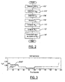
- Figure 3 shows a graph of estimated MAF using equation (31) (line 202) versus the measured MAF (line 200) over a period of 200 seconds.
- the control schemes further differ on the basis of the underlying assumptions regarding the processes in the intake manifold. Specifically, adiabatic for equations (11) - (13) and (24) - (27) and isothermic for equations (14) - (16) and (28) - (31).
- the adiabatic assumption results in higher transient accuracy, provided the temperature measurements or estimates are accurate. If the temperature measurements or estimates contain large errors, the control scheme based on the isothermic assumptions proves more accurate.
Landscapes
- Engineering & Computer Science (AREA)
- Chemical & Material Sciences (AREA)
- Combustion & Propulsion (AREA)
- Mechanical Engineering (AREA)
- General Engineering & Computer Science (AREA)
- Combined Controls Of Internal Combustion Engines (AREA)
- Exhaust-Gas Circulating Devices (AREA)
Claims (9)
- Ein Verfahren der Berechnung des Luftstroms in einen Kompressor eines turbogeladenen Dieselmotors hinein, der ein Abgasrückführungs-System (12) besitzt, das ein Ansaugkrümmer (26) und Abgaskrümmer (28) des Motors verbindendes Ventil (34) aufweist, wobei das Verfahren die Schritte umfaßt:Messen eines Ansaugdruckwertes (p1), welcher für den Ansaugkrümmerdruck bezeichnend ist;Messen eines Abgasdruckwertes (p2), welcher für den Abgaskrümmerdruck bezeichnend ist;Bestimmen eines ersten Werts (αegr), der für die Stellung des Abgasrückführungs-Ventils (34) bezeichnend ist;Bestimmen eines ersten Temperaturwerts (T21), der für die Temperatur des durch das Abgasrückführungs-System (12) strömenden Abgases bezeichnend ist;Messen eines zweiten Temperaturwerts (Tc1), der für die Temperatur der in den Ansaugkrümmer (26) des Motors eintretende Luftladung bezeichnend ist;Berechnen eines Abasrückführungs-Stromwertes (W21) als eine Funktion von p1, p2, T21 und αegr; undBerechnen eines Kompressor-Luftstromwertes (Wo1) als eine Funktion dieses Abgasrückführungs-Stromwertes (W21) und dieses zweiten Temperaturwertes (To1), wobei dieser Kompressor-Luftstromwert verwendet wird um die Stellung dieses Abgasrückführungs-Ventils (34) zu steuern.
- Ein Verfahren gemäß Anspruch 1, in dem der Schritt der Bestimmung eines eisten Temperaturwertes (T21) den Schritt einschließt diesen ersten Temgeraturwert aus einer Tabelle von Werten abzurufen, die nach der Motordrehzahl indiziert ist.
- Ein Verfahren gemäß Anspruch 1, in dem der Schritt der Bestimmung eines ersten Temperaturwertes (T21) den Schritt einschließt diesen ersten Temperaturwert aus einer Tabelle von Werten abzurufen, die nach Motordrehzahl, Kraftstofförderung und Kraftstoff-Einspritzzeit indiziert ist.
- Ein Verfahren gemäß Anspruch 1, in dem der Schritt der Berechnung eines Abgasrückführungs-Stromwertes (W21) durch die folgende Gleichung geregelt ist:
- Ein Verfahren gemäß Anspruch 4, in dem der Schritt der Berechnung des Kompressor-Luftstromwerts (Wc1) durch die folgende Gleichung geregelt ist:
- Ein Verfahren gemäß Anspruch 4, in dem der Schritt der Berechnung des Kompressor-Luftstromwertes (Wc1) den Schritt der Berechnung von Wc1 über diskrete Abtastdauem, δt, hinweg einschließt, wobei der Wert von Wc1 durch die folgende Gleichung geregelt wird:
- Ein Verfahren gemäß Anspruch 4, in dem der Schritt der Berechnung eines Kompressor-Luftstromwerts (Wc1) den Schritt der Berechnung von Wc1 über diskrete Abtastdauem, δt, hinweg einschließt, wobei der Wert von Wc1 durch die folgende Gleichung geregelt wird:
- Ein Verfahren gemäß Anspruch 4, in dem der Schritt der Berechnung eines Kompressor-Luftstromwertes (Wc1) den Schritt der Berechnung von Wc1 über diskrete Abtastdauem, δt, hinweg einschließt, wobei der Wert von Wc1 durch die folgende Gleichung geregelt wird:
- Ein Verfahren gemäß Anspruch 4, in dem der Schritt der Berechnung eines Kompressor-Luftstromwertes (Wc1) den Schritt der Berechnung von Wc1 über diskrete Abtastdauem, δt, hinweg einschließt, wobei der Wert von Wc1 durch die folgende Gleichung geregelt wird:
Applications Claiming Priority (2)
| Application Number | Priority Date | Filing Date | Title |
|---|---|---|---|
| US236991 | 1994-05-02 | ||
| US09/236,991 US6035639A (en) | 1999-01-26 | 1999-01-26 | Method of estimating mass airflow in turbocharged engines having exhaust gas recirculation |
Publications (3)
| Publication Number | Publication Date |
|---|---|
| EP1024262A2 EP1024262A2 (de) | 2000-08-02 |
| EP1024262A3 EP1024262A3 (de) | 2000-08-30 |
| EP1024262B1 true EP1024262B1 (de) | 2003-04-23 |
Family
ID=22891871
Family Applications (1)
| Application Number | Title | Priority Date | Filing Date |
|---|---|---|---|
| EP00300287A Expired - Lifetime EP1024262B1 (de) | 1999-01-26 | 2000-01-17 | Verfahren zur Schätzung des Luftmassenstroms bei einem turboaufgeladenen Dieselmotor mit Abgasrückführung |
Country Status (3)
| Country | Link |
|---|---|
| US (1) | US6035639A (de) |
| EP (1) | EP1024262B1 (de) |
| DE (1) | DE60002238T2 (de) |
Families Citing this family (92)
| Publication number | Priority date | Publication date | Assignee | Title |
|---|---|---|---|---|
| US8215292B2 (en) | 1996-07-17 | 2012-07-10 | Bryant Clyde C | Internal combustion engine and working cycle |
| US6951211B2 (en) | 1996-07-17 | 2005-10-04 | Bryant Clyde C | Cold air super-charged internal combustion engine, working cycle and method |
| US7222614B2 (en) | 1996-07-17 | 2007-05-29 | Bryant Clyde C | Internal combustion engine and working cycle |
| US7281527B1 (en) | 1996-07-17 | 2007-10-16 | Bryant Clyde C | Internal combustion engine and working cycle |
| US6145313A (en) * | 1997-03-03 | 2000-11-14 | Allied Signal Inc. | Turbocharger incorporating an integral pump for exhaust gas recirculation |
| JP3430923B2 (ja) * | 1998-06-15 | 2003-07-28 | 日産自動車株式会社 | 内燃機関の過給制御装置 |
| US6178749B1 (en) * | 1999-01-26 | 2001-01-30 | Ford Motor Company | Method of reducing turbo lag in diesel engines having exhaust gas recirculation |
| US6128902A (en) * | 1999-01-26 | 2000-10-10 | Ford Global Technologies, Inc. | Control method and apparatus for turbocharged diesel engines having exhaust gas recirculation |
| DE19913792A1 (de) * | 1999-03-26 | 2000-10-05 | Daimler Chrysler Ag | Verfahren zum Betrieb einer aufgeladenen Brennkraftmaschine |
| US6354084B1 (en) * | 1999-08-20 | 2002-03-12 | Cummins Engine Company, Inc. | Exhaust gas recirculation system for a turbocharged internal combustion engine |
| DE60029474T2 (de) | 1999-12-09 | 2007-02-15 | International Engine Intellectual Property Company, LLC., Warrenville | Ergeignis-Überwachungssystem in einem Abgas-Rückführungs-System eines Verbrennungsmotors |
| US6470866B2 (en) * | 2000-01-05 | 2002-10-29 | Siemens Canada Limited | Diesel engine exhaust gas recirculation (EGR) system and method |
| US6360541B2 (en) * | 2000-03-03 | 2002-03-26 | Honeywell International, Inc. | Intelligent electric actuator for control of a turbocharger with an integrated exhaust gas recirculation valve |
| US6347519B1 (en) * | 2000-03-31 | 2002-02-19 | Detroit Diesel Corporation | System and method for measuring recirculated exhaust gas flow in a compression-ignition engine |
| ATE418675T1 (de) * | 2000-03-31 | 2009-01-15 | Detroit Diesel Corp | Verfahren zum regeln einer brennkraftmaschine |
| JP3687485B2 (ja) | 2000-05-12 | 2005-08-24 | 日産自動車株式会社 | ディーゼルエンジンの制御装置 |
| US6378515B1 (en) * | 2000-06-09 | 2002-04-30 | Mack Trucks, Inc. | Exhaust gas recirculation apparatus and method |
| US6543227B2 (en) | 2001-01-31 | 2003-04-08 | Cummins Engine Company, Inc. | Automated active variable geometry turbocharger diagnosis system |
| FR2824596B1 (fr) * | 2001-05-14 | 2003-12-12 | Renault | Procede pour estimer le debit d'air dans un moteur et dispositif de controle du fonctionnement d'un tel moteur |
| US6708104B2 (en) | 2001-07-27 | 2004-03-16 | Detroit Diesel Corporation | Engine control based on exhaust back pressure |
| EP1507967A2 (de) * | 2001-11-28 | 2005-02-23 | Volkswagen Aktiengesellschaft | Verfahren zur bestimmung der zusammensetzung des gasgemisches in einem brennraum eines verbrennungsmotors mit abgasrückführung |
| US6711489B2 (en) | 2001-12-05 | 2004-03-23 | Visteon Global Technologies, Inc. | Method for estimating engine cylinder variables using second order sliding modes |
| GB2388922B (en) * | 2002-01-31 | 2005-06-08 | Cambridge Consultants | Control system |
| US7178492B2 (en) | 2002-05-14 | 2007-02-20 | Caterpillar Inc | Air and fuel supply system for combustion engine |
| US6722349B2 (en) | 2002-02-04 | 2004-04-20 | Caterpillar Inc | Efficient internal combustion engine valve actuator |
| US6688280B2 (en) | 2002-05-14 | 2004-02-10 | Caterpillar Inc | Air and fuel supply system for combustion engine |
| US20050247286A1 (en) * | 2002-02-04 | 2005-11-10 | Weber James R | Combustion engine including fluidically-controlled engine valve actuator |
| US6732685B2 (en) | 2002-02-04 | 2004-05-11 | Caterpillar Inc | Engine valve actuator |
| US7347171B2 (en) * | 2002-02-04 | 2008-03-25 | Caterpillar Inc. | Engine valve actuator providing Miller cycle benefits |
| US7201121B2 (en) | 2002-02-04 | 2007-04-10 | Caterpillar Inc | Combustion engine including fluidically-driven engine valve actuator |
| US6697729B2 (en) * | 2002-04-08 | 2004-02-24 | Cummins, Inc. | System for estimating NOx content of exhaust gas produced by an internal combustion engine |
| US6732522B2 (en) | 2002-04-08 | 2004-05-11 | Cummins, Inc. | System for estimating engine exhaust pressure |
| US20050235950A1 (en) * | 2002-05-14 | 2005-10-27 | Weber James R | Air and fuel supply system for combustion engine |
| US20050247284A1 (en) * | 2002-05-14 | 2005-11-10 | Weber James R | Air and fuel supply system for combustion engine operating at optimum engine speed |
| US20050241597A1 (en) * | 2002-05-14 | 2005-11-03 | Weber James R | Air and fuel supply system for a combustion engine |
| US7191743B2 (en) * | 2002-05-14 | 2007-03-20 | Caterpillar Inc | Air and fuel supply system for a combustion engine |
| US7004122B2 (en) * | 2002-05-14 | 2006-02-28 | Caterpillar Inc | Engine valve actuation system |
| US7069887B2 (en) * | 2002-05-14 | 2006-07-04 | Caterpillar Inc. | Engine valve actuation system |
| US6941909B2 (en) * | 2003-06-10 | 2005-09-13 | Caterpillar Inc | System and method for actuating an engine valve |
| US7252054B2 (en) | 2002-05-14 | 2007-08-07 | Caterpillar Inc | Combustion engine including cam phase-shifting |
| US6742335B2 (en) | 2002-07-11 | 2004-06-01 | Clean Air Power, Inc. | EGR control system and method for an internal combustion engine |
| JP3861046B2 (ja) * | 2002-11-01 | 2006-12-20 | トヨタ自動車株式会社 | 内燃機関のegrガス流量推定装置 |
| US6805095B2 (en) * | 2002-11-05 | 2004-10-19 | Ford Global Technologies, Llc | System and method for estimating and controlling cylinder air charge in a direct injection internal combustion engine |
| US6948475B1 (en) | 2002-11-12 | 2005-09-27 | Clean Air Power, Inc. | Optimized combustion control of an internal combustion engine equipped with exhaust gas recirculation |
| US20040144082A1 (en) * | 2003-01-29 | 2004-07-29 | Visteon Global Technologies, Inc. | Controller for controlling oxides of nitrogen (NOx) emissions from a combustion engine |
| US6912458B2 (en) * | 2003-06-25 | 2005-06-28 | Caterpillar Inc | Variable valve actuation control for operation at altitude |
| WO2005019619A1 (en) * | 2003-08-18 | 2005-03-03 | Bryant, Clyde, C. | Improved internal combustion engine and working cycle |
| JP3956137B2 (ja) * | 2003-09-18 | 2007-08-08 | トヨタ自動車株式会社 | 内燃機関の混合気温度推定方法 |
| US8191369B2 (en) * | 2003-11-12 | 2012-06-05 | Mack Trucks, Inc. | Turbo-charger surge detection |
| GB0403718D0 (en) * | 2004-02-19 | 2004-03-24 | Epicam Ltd | An engine and an apparatus for providing forced aspiration to an engine |
| FR2868128B1 (fr) * | 2004-03-29 | 2007-11-23 | Renault Sas | Procede et systeme de commande du fonctionnement d'un moteur a combustion interne de vehicule automobile equipe d'un ensemble turbocompresseur de suralimentation |
| DE602004012986T2 (de) | 2004-06-15 | 2009-06-04 | C.R.F. Società Consortile per Azioni, Orbassano | Verfahren und Einrichtung zur Bestimmung der Ansaugluftmenge einer Brennkraftmaschine basierend auf der Messung der Sauerstoffkonzentration in einem der Brennkraftmaschine zugeführten Gasgemisch |
| FR2872220B1 (fr) * | 2004-06-24 | 2008-10-31 | Renault Sas | Procede de commande d'un debit de gaz d'echappement recircules dans un moteur de vehicule |
| JP2006029247A (ja) * | 2004-07-20 | 2006-02-02 | Denso Corp | エンジンの停止始動制御装置 |
| FR2878575B1 (fr) * | 2004-11-30 | 2007-04-06 | Peugeot Citroen Automobiles Sa | Procede de regulation d'un systeme d'admission d'un moteur a combustion interne et vehicule automobile pour la mise en oeuvre du procede |
| DE102004061454A1 (de) * | 2004-12-17 | 2006-06-29 | Delphi Technologies, Inc., Troy | Verfahren und Vorrichtung zur Motorsteuerung bei einem Kraftfahrzeug |
| DE102005015609B4 (de) * | 2005-04-05 | 2008-01-17 | Siemens Ag | Vorrichtung zum Steuern einer Brennkraftmaschine |
| US20070079598A1 (en) * | 2005-10-06 | 2007-04-12 | Bailey Brett M | Gaseous fuel engine charge density control system |
| US7913675B2 (en) * | 2005-10-06 | 2011-03-29 | Caterpillar Inc. | Gaseous fuel engine charge density control system |
| US7296562B2 (en) * | 2006-03-30 | 2007-11-20 | Caterpiller Inc. | Control system and method for estimating turbocharger performance |
| FR2910934B1 (fr) * | 2006-12-27 | 2009-01-30 | Renault Sas | Procede d'estimation et systeme de controle du taux d'egr sur un moteur suralimente par un turbocompresseur et equipe de deux collecteurs d'admission et d'un volet de swirl. |
| US7814752B2 (en) * | 2007-02-28 | 2010-10-19 | Caterpillar Inc | Decoupling control strategy for interrelated air system components |
| US8151567B2 (en) * | 2007-05-29 | 2012-04-10 | Ford Global Technologies, Llc | Adaptive learning system and method of vane position for a variable geometry turbocharger |
| DE102007046146A1 (de) * | 2007-09-27 | 2009-04-02 | Daimler Ag | Verfahren zur Schätzung einer externen Abgasrückführrate |
| US8986253B2 (en) | 2008-01-25 | 2015-03-24 | Tandem Diabetes Care, Inc. | Two chamber pumps and related methods |
| FR2931891B1 (fr) * | 2008-05-28 | 2010-08-20 | Renault Sas | Procede d'estimation du debit de recirculation des gaz d'echappement sur un moteur bi plenum avec volet de turbulence. |
| FR2931892B1 (fr) * | 2008-05-28 | 2010-08-20 | Renault Sas | Procede d'estimation du debit de recirculation des gaz d'echappement sur un moteur bi-plenum avec volet de turbulence |
| US8408421B2 (en) | 2008-09-16 | 2013-04-02 | Tandem Diabetes Care, Inc. | Flow regulating stopcocks and related methods |
| CA2737461A1 (en) | 2008-09-19 | 2010-03-25 | Tandem Diabetes Care, Inc. | Solute concentration measurement device and related methods |
| US8926561B2 (en) | 2009-07-30 | 2015-01-06 | Tandem Diabetes Care, Inc. | Infusion pump system with disposable cartridge having pressure venting and pressure feedback |
| US8201442B2 (en) * | 2009-09-25 | 2012-06-19 | Cummins Inc. | System and method for estimating EGR mass flow rates |
| JP5133332B2 (ja) * | 2009-12-15 | 2013-01-30 | 日立オートモティブシステムズ株式会社 | 内燃機関の制御装置 |
| GB2484297A (en) * | 2010-10-05 | 2012-04-11 | Gm Global Tech Operations Inc | A combustion engine evaluation unit comprising fault detection system for engine using EGR |
| FR2965584B1 (fr) * | 2010-10-05 | 2013-06-28 | Renault Sas | Procede de determination d'un taux de gaz d'echappement recircules a l'entree d'un cylindre d'un moteur a combustion interne et moteur mettant en oeuvre un tel procede |
| US8880321B2 (en) | 2011-03-07 | 2014-11-04 | Toyota Motor Engineering & Manufacturing North America, Inc. | Adaptive air charge estimation based on support vector regression |
| US8857178B2 (en) * | 2011-06-28 | 2014-10-14 | Caterpillar Inc. | Nozzled turbocharger turbine and associated engine and method |
| US9140203B2 (en) | 2011-11-15 | 2015-09-22 | Cummins Inc. | Apparent plumbing volume of air intake and fresh airflow value determination |
| CN102493896A (zh) * | 2011-12-14 | 2012-06-13 | 重庆长安汽车股份有限公司 | 用于egr发动机的排气歧管 |
| EP2623758B1 (de) * | 2012-01-31 | 2018-10-24 | International Engine Intellectual Property Company, LLC | Turboladersteuerung |
| US9180242B2 (en) | 2012-05-17 | 2015-11-10 | Tandem Diabetes Care, Inc. | Methods and devices for multiple fluid transfer |
| US9173998B2 (en) | 2013-03-14 | 2015-11-03 | Tandem Diabetes Care, Inc. | System and method for detecting occlusions in an infusion pump |
| FR3006375A1 (fr) | 2013-06-03 | 2014-12-05 | Renault Sa | Systeme et procede de determination de la fraction massique de gaz frais dans le collecteur d'admission d'un moteur a combustion interne de vehicule automobile. |
| US9422877B2 (en) | 2013-10-11 | 2016-08-23 | General Electric Company | System and method for control of exhaust gas recirculation (EGR) utilizing process temperatures |
| DE102014201947B3 (de) * | 2014-02-04 | 2015-01-22 | Ford Global Technologies, Llc | Verfahren und Vorrichtung zur Bestimmung eines Ladeluftmassenstroms |
| DE102014013284A1 (de) * | 2014-09-12 | 2016-03-17 | Man Truck & Bus Ag | Brennkraftmaschine, insbesondere Gasmotor, für ein Fahrzeug, insbesondere für ein Nutzfahrzeug |
| US9951701B2 (en) * | 2014-09-22 | 2018-04-24 | General Electric Company | Method and systems for EGR control |
| DE102016207360A1 (de) | 2016-04-29 | 2017-11-02 | Ford Global Technologies, Llc | Verfahren zur Prognose der Abgasrückführungsrate |
| US10330034B2 (en) | 2016-04-29 | 2019-06-25 | Ford Global Technologies, Llc | Device and method for predicting the exhaust gas recirculation rate |
| DE102016207358B4 (de) | 2016-04-29 | 2024-01-11 | Ford Global Technologies, Llc | Vorrichtung und Verfahren zur Prognose der Abgasrückführungsrate |
| DE102017205829A1 (de) | 2017-04-05 | 2018-10-11 | Robert Bosch Gmbh | Verfahren und Vorrichtung zum Bestimmen einer Gassystemgröße in einem Verbrennungsmotor |
| CN116447052B (zh) * | 2023-04-27 | 2025-09-19 | 潍柴动力股份有限公司 | Egr模块压力传感器检测方法、装置、车辆及存储介质 |
| CN117072304B (zh) * | 2023-07-28 | 2026-04-21 | 西华大学 | 涡轮增压发动机全流程能量控制方法 |
Citations (1)
| Publication number | Priority date | Publication date | Assignee | Title |
|---|---|---|---|---|
| DE19728352C1 (de) * | 1997-07-03 | 1998-08-20 | Daimler Benz Ag | Verfahren zur Regelung der Aufladung einer Brennkraftmaschine mit einem Abgasturbolader mit verstellbarer Turbinengeometrie |
Family Cites Families (16)
| Publication number | Priority date | Publication date | Assignee | Title |
|---|---|---|---|---|
| JPS56167814A (en) * | 1980-05-28 | 1981-12-23 | Hitachi Ltd | Apparatus and method for controlling supercharger of internal combustion engine |
| DE3444877A1 (de) * | 1984-08-14 | 1986-04-17 | Robert Bosch Gmbh, 7000 Stuttgart | Steuereinrichtung fuer eine brennkraftmaschine und verfahren zur steuerung von den brennraeumen einer selbstzuendenden brennkraftmaschine zugefuehrten gasen bestehend aus luft und abgasrueckfuehrmengen |
| US5228292A (en) * | 1990-08-16 | 1993-07-20 | Mercedes-Benz Ag | Arrangement for controlling the boost pressure in an internal-combustion engine supercharged by an exhaust-gas turbocharger of adjustable turbine geometry |
| US5273019A (en) * | 1990-11-26 | 1993-12-28 | General Motors Corporation | Apparatus with dynamic prediction of EGR in the intake manifold |
| US5123246A (en) * | 1991-01-25 | 1992-06-23 | Mack Trucks, Inc. | Continuously proportional variable geometry turbocharger system and method of control |
| US5333456A (en) * | 1992-10-01 | 1994-08-02 | Carter Automotive Company, Inc. | Engine exhaust gas recirculation control mechanism |
| DE69530721T2 (de) * | 1994-04-14 | 2004-03-18 | Honda Giken Kogyo K.K. | System zur Schätzung der Abgasrückführungsrate für einen Verbrennungsmotor |
| JP3298358B2 (ja) * | 1995-04-25 | 2002-07-02 | 日産自動車株式会社 | ディーゼルエンジンにおける圧縮端温度制御方法および制御装置 |
| DE69636687T2 (de) * | 1995-06-02 | 2007-10-18 | Mitsubishi Jidosha Kogyo K.K. | Vorrichtung zum erfassen und steurern des luftüberschussfaktors einer brennkraftmaschine |
| US5601068A (en) * | 1995-07-05 | 1997-02-11 | Nozel Engineering Co., Ltd. | Method and apparatus for controlling a diesel engine |
| CA2154011C (en) * | 1995-07-17 | 1999-06-08 | Gerhard O. Klopp | Exhaust gas recirculation system for a compression ignition engine and a method of controlling exhaust gas recirculation in a compression ignition engine |
| IT1284345B1 (it) * | 1996-01-26 | 1998-05-18 | Fiat Ricerche | Metodo e unita' di controllo della pressione di sovralimentazione per un motore turbodiesel con turbina a geometria variabile |
| DE19607071C2 (de) * | 1996-02-24 | 1997-12-18 | Bosch Gmbh Robert | Verfahren und Vorrichtung zur Steuerung einer Brennkraftmaschine |
| DE19615545C1 (de) * | 1996-04-19 | 1997-06-12 | Daimler Benz Ag | Einrichtung zur Dieselmotorbetriebsregelung mit Abgasrückführung und Ansaugluftdrosselung |
| JP3551675B2 (ja) * | 1997-01-21 | 2004-08-11 | 日産自動車株式会社 | 内燃機関のegr制御装置 |
| DE19756619B4 (de) * | 1997-04-01 | 2007-03-15 | Robert Bosch Gmbh | System zum Betreiben einer Brennkraftmaschine insbesondere für ein Kraftfahrzeug |
-
1999
- 1999-01-26 US US09/236,991 patent/US6035639A/en not_active Expired - Fee Related
-
2000
- 2000-01-17 EP EP00300287A patent/EP1024262B1/de not_active Expired - Lifetime
- 2000-01-17 DE DE60002238T patent/DE60002238T2/de not_active Expired - Fee Related
Patent Citations (1)
| Publication number | Priority date | Publication date | Assignee | Title |
|---|---|---|---|---|
| DE19728352C1 (de) * | 1997-07-03 | 1998-08-20 | Daimler Benz Ag | Verfahren zur Regelung der Aufladung einer Brennkraftmaschine mit einem Abgasturbolader mit verstellbarer Turbinengeometrie |
Also Published As
| Publication number | Publication date |
|---|---|
| DE60002238D1 (de) | 2003-05-28 |
| US6035639A (en) | 2000-03-14 |
| EP1024262A2 (de) | 2000-08-02 |
| EP1024262A3 (de) | 2000-08-30 |
| DE60002238T2 (de) | 2003-11-06 |
Similar Documents
| Publication | Publication Date | Title |
|---|---|---|
| EP1024262B1 (de) | Verfahren zur Schätzung des Luftmassenstroms bei einem turboaufgeladenen Dieselmotor mit Abgasrückführung | |
| EP1024272B1 (de) | Steuerungsverfahren für einen turboaufgeladenen Dieselmotor mit Abgasrückführung | |
| EP1024275B1 (de) | Kraftstoffbegrenzungsmethode für eine Dieselbrennkraftmaschine mit Abgasrückführung | |
| EP1024260B1 (de) | Steuerungsverfahren für einen Turbolader variabler Geometrie in einem Dieselmotor mit Abgasrückführung | |
| EP1024263B1 (de) | Steuerungsverfahren für einen turboaufgeladenen Dieselmotor mit Abgasrückführung | |
| EP1024264B1 (de) | Steuerungsverfahren für einen turboaufgeladenen Dieselmotor mit Abgasrückführung | |
| US8387593B2 (en) | EGR flow rate control apparatus of internal combustion engine | |
| US5738126A (en) | Apparatus for controlling a diesel engine with exhaust | |
| US7150264B2 (en) | Control device for internal combustion engine | |
| US7100375B2 (en) | System for limiting rotational speed of a turbocharger | |
| EP1227233A1 (de) | Verfahren und System zur Schätzung der Zylinderluftmenge einer Brennkraftmaschine | |
| JP4706134B2 (ja) | 内燃機関の制御装置 | |
| EP1358399B1 (de) | Vorrichtung und verfahren zur steuerung des kraftstoff-luft-gemisches | |
| US6390081B1 (en) | Method and device for determining temperature values in a combustion engine | |
| US5381775A (en) | System for controlling an internal combustion engine | |
| WO2001075287A1 (en) | System and method for measuring recirculated exhaust gas flow in a compression-ignition engine | |
| CA2048085A1 (en) | Method and apparatus for inferring barometric pressure surrounding an internal combustion engine | |
| US6009862A (en) | Exhaust gas recirculation control system and method | |
| US20030075158A1 (en) | Method and device for a mass flow determination via a control valve and for determining a modeled induction pipe pressure | |
| US7805940B2 (en) | Method and device for the control and diagnosis of an exhaust gas turbocharger | |
| JP3966243B2 (ja) | 内燃機関 | |
| CN106150714A (zh) | 内燃机的控制装置以及控制方法 | |
| JP3551706B2 (ja) | エンジンの吸気制御装置 | |
| EP1482153B1 (de) | Brennkraftmaschine und Verfahren zur Steuerung des Ladeluftmassenstroms und der Abgasrückführungsrate | |
| JPH1018918A (ja) | 内燃機関の排気還流制御装置 |
Legal Events
| Date | Code | Title | Description |
|---|---|---|---|
| PUAI | Public reference made under article 153(3) epc to a published international application that has entered the european phase |
Free format text: ORIGINAL CODE: 0009012 |
|
| PUAL | Search report despatched |
Free format text: ORIGINAL CODE: 0009013 |
|
| AK | Designated contracting states |
Kind code of ref document: A2 Designated state(s): DE FR GB |
|
| AX | Request for extension of the european patent |
Free format text: AL;LT;LV;MK;RO;SI |
|
| AK | Designated contracting states |
Kind code of ref document: A3 Designated state(s): AT BE CH CY DE DK ES FI FR GB GR IE IT LI LU MC NL PT SE |
|
| AX | Request for extension of the european patent |
Free format text: AL;LT;LV;MK;RO;SI |
|
| RIC1 | Information provided on ipc code assigned before grant |
Free format text: 7F 02B 37/24 A, 7F 02D 21/08 B, 7F 02D 35/00 B, 7F 02D 33/02 B |
|
| 17P | Request for examination filed |
Effective date: 20010116 |
|
| 17Q | First examination report despatched |
Effective date: 20010323 |
|
| AKX | Designation fees paid |
Free format text: DE FR GB |
|
| GRAH | Despatch of communication of intention to grant a patent |
Free format text: ORIGINAL CODE: EPIDOS IGRA |
|
| GRAH | Despatch of communication of intention to grant a patent |
Free format text: ORIGINAL CODE: EPIDOS IGRA |
|
| GRAA | (expected) grant |
Free format text: ORIGINAL CODE: 0009210 |
|
| AK | Designated contracting states |
Designated state(s): DE FR GB |
|
| PG25 | Lapsed in a contracting state [announced via postgrant information from national office to epo] |
Ref country code: FR Free format text: LAPSE BECAUSE OF FAILURE TO SUBMIT A TRANSLATION OF THE DESCRIPTION OR TO PAY THE FEE WITHIN THE PRESCRIBED TIME-LIMIT Effective date: 20030423 |
|
| REG | Reference to a national code |
Ref country code: GB Ref legal event code: FG4D |
|
| REF | Corresponds to: |
Ref document number: 60002238 Country of ref document: DE Date of ref document: 20030528 Kind code of ref document: P |
|
| PG25 | Lapsed in a contracting state [announced via postgrant information from national office to epo] |
Ref country code: GB Free format text: LAPSE BECAUSE OF NON-PAYMENT OF DUE FEES Effective date: 20040117 |
|
| PGFP | Annual fee paid to national office [announced via postgrant information from national office to epo] |
Ref country code: DE Payment date: 20040130 Year of fee payment: 5 |
|
| PLBE | No opposition filed within time limit |
Free format text: ORIGINAL CODE: 0009261 |
|
| STAA | Information on the status of an ep patent application or granted ep patent |
Free format text: STATUS: NO OPPOSITION FILED WITHIN TIME LIMIT |
|
| 26N | No opposition filed |
Effective date: 20040126 |
|
| EN | Fr: translation not filed | ||
| GBPC | Gb: european patent ceased through non-payment of renewal fee |
Effective date: 20040117 |
|
| PG25 | Lapsed in a contracting state [announced via postgrant information from national office to epo] |
Ref country code: DE Free format text: LAPSE BECAUSE OF NON-PAYMENT OF DUE FEES Effective date: 20050802 |