EP1024187A1 - Verfahren zum Gewinnen einer Ethylen-reichen Fraktion - Google Patents
Verfahren zum Gewinnen einer Ethylen-reichen Fraktion Download PDFInfo
- Publication number
- EP1024187A1 EP1024187A1 EP00101793A EP00101793A EP1024187A1 EP 1024187 A1 EP1024187 A1 EP 1024187A1 EP 00101793 A EP00101793 A EP 00101793A EP 00101793 A EP00101793 A EP 00101793A EP 1024187 A1 EP1024187 A1 EP 1024187A1
- Authority
- EP
- European Patent Office
- Prior art keywords
- fraction
- separation
- adsorption
- components
- adsorptive
- Prior art date
- Legal status (The legal status is an assumption and is not a legal conclusion. Google has not performed a legal analysis and makes no representation as to the accuracy of the status listed.)
- Withdrawn
Links
- 238000000034 method Methods 0.000 title claims abstract description 55
- VGGSQFUCUMXWEO-UHFFFAOYSA-N Ethene Chemical compound C=C VGGSQFUCUMXWEO-UHFFFAOYSA-N 0.000 title claims abstract description 22
- 239000005977 Ethylene Substances 0.000 title claims abstract description 22
- 238000000926 separation method Methods 0.000 claims abstract description 83
- 238000001179 sorption measurement Methods 0.000 claims abstract description 29
- 150000001336 alkenes Chemical class 0.000 claims abstract description 24
- JRZJOMJEPLMPRA-UHFFFAOYSA-N olefin Natural products CCCCCCCC=C JRZJOMJEPLMPRA-UHFFFAOYSA-N 0.000 claims abstract description 21
- 238000005336 cracking Methods 0.000 claims abstract description 18
- 230000000274 adsorptive effect Effects 0.000 claims abstract description 17
- OKTJSMMVPCPJKN-UHFFFAOYSA-N Carbon Chemical compound [C] OKTJSMMVPCPJKN-UHFFFAOYSA-N 0.000 claims description 8
- 239000003463 adsorbent Substances 0.000 claims description 8
- VYPSYNLAJGMNEJ-UHFFFAOYSA-N Silicium dioxide Chemical compound O=[Si]=O VYPSYNLAJGMNEJ-UHFFFAOYSA-N 0.000 claims description 4
- 239000000499 gel Substances 0.000 claims description 4
- 150000002500 ions Chemical class 0.000 claims description 4
- 239000012466 permeate Substances 0.000 claims description 4
- 238000010926 purge Methods 0.000 claims description 3
- XAGFODPZIPBFFR-UHFFFAOYSA-N aluminium Chemical compound [Al] XAGFODPZIPBFFR-UHFFFAOYSA-N 0.000 claims description 2
- 229910052782 aluminium Inorganic materials 0.000 claims description 2
- 239000000463 material Substances 0.000 claims description 2
- 230000008929 regeneration Effects 0.000 claims description 2
- 238000011069 regeneration method Methods 0.000 claims description 2
- 239000000377 silicon dioxide Substances 0.000 claims description 2
- 239000010457 zeolite Substances 0.000 claims description 2
- 238000005371 permeation separation Methods 0.000 claims 1
- 239000007789 gas Substances 0.000 description 32
- VNWKTOKETHGBQD-UHFFFAOYSA-N methane Chemical compound C VNWKTOKETHGBQD-UHFFFAOYSA-N 0.000 description 10
- 239000012528 membrane Substances 0.000 description 9
- 238000010438 heat treatment Methods 0.000 description 8
- 239000000047 product Substances 0.000 description 7
- QQONPFPTGQHPMA-UHFFFAOYSA-N propylene Natural products CC=C QQONPFPTGQHPMA-UHFFFAOYSA-N 0.000 description 6
- 125000004805 propylene group Chemical group [H]C([H])([H])C([H])([*:1])C([H])([H])[*:2] 0.000 description 6
- 238000001816 cooling Methods 0.000 description 5
- ATUOYWHBWRKTHZ-UHFFFAOYSA-N Propane Chemical compound CCC ATUOYWHBWRKTHZ-UHFFFAOYSA-N 0.000 description 4
- 239000002737 fuel gas Substances 0.000 description 3
- OTMSDBZUPAUEDD-UHFFFAOYSA-N Ethane Chemical compound CC OTMSDBZUPAUEDD-UHFFFAOYSA-N 0.000 description 2
- OFBQJSOFQDEBGM-UHFFFAOYSA-N Pentane Chemical compound CCCCC OFBQJSOFQDEBGM-UHFFFAOYSA-N 0.000 description 2
- 238000010521 absorption reaction Methods 0.000 description 2
- 239000002253 acid Substances 0.000 description 2
- 238000006243 chemical reaction Methods 0.000 description 2
- 230000018109 developmental process Effects 0.000 description 2
- 238000005194 fractionation Methods 0.000 description 2
- 238000005984 hydrogenation reaction Methods 0.000 description 2
- 239000001294 propane Substances 0.000 description 2
- 238000000746 purification Methods 0.000 description 2
- 239000003507 refrigerant Substances 0.000 description 2
- 239000004215 Carbon black (E152) Substances 0.000 description 1
- 238000002485 combustion reaction Methods 0.000 description 1
- 238000007906 compression Methods 0.000 description 1
- LJVYOZJXUGFDJA-UHFFFAOYSA-N copane Chemical compound C1CC(C)C2C3(C)CCC(C(C)C)C2C31 LJVYOZJXUGFDJA-UHFFFAOYSA-N 0.000 description 1
- 239000010949 copper Substances 0.000 description 1
- ORTQZVOHEJQUHG-UHFFFAOYSA-L copper(II) chloride Chemical compound Cl[Cu]Cl ORTQZVOHEJQUHG-UHFFFAOYSA-L 0.000 description 1
- 238000006356 dehydrogenation reaction Methods 0.000 description 1
- 239000003599 detergent Substances 0.000 description 1
- 238000001035 drying Methods 0.000 description 1
- 238000000605 extraction Methods 0.000 description 1
- 230000004992 fission Effects 0.000 description 1
- -1 for example Chemical class 0.000 description 1
- 229930195733 hydrocarbon Natural products 0.000 description 1
- 150000002430 hydrocarbons Chemical class 0.000 description 1
- 239000007788 liquid Substances 0.000 description 1
- 238000004519 manufacturing process Methods 0.000 description 1
- 239000000203 mixture Substances 0.000 description 1
- JTXAHXNXKFGXIT-UHFFFAOYSA-N propane;prop-1-ene Chemical group CCC.CC=C JTXAHXNXKFGXIT-UHFFFAOYSA-N 0.000 description 1
- 238000010992 reflux Methods 0.000 description 1
- 238000005057 refrigeration Methods 0.000 description 1
- 230000000717 retained effect Effects 0.000 description 1
- 238000005201 scrubbing Methods 0.000 description 1
- 238000005406 washing Methods 0.000 description 1
Images
Classifications
-
- C—CHEMISTRY; METALLURGY
- C10—PETROLEUM, GAS OR COKE INDUSTRIES; TECHNICAL GASES CONTAINING CARBON MONOXIDE; FUELS; LUBRICANTS; PEAT
- C10G—CRACKING HYDROCARBON OILS; PRODUCTION OF LIQUID HYDROCARBON MIXTURES, e.g. BY DESTRUCTIVE HYDROGENATION, OLIGOMERISATION, POLYMERISATION; RECOVERY OF HYDROCARBON OILS FROM OIL-SHALE, OIL-SAND, OR GASES; REFINING MIXTURES MAINLY CONSISTING OF HYDROCARBONS; REFORMING OF NAPHTHA; MINERAL WAXES
- C10G70/00—Working-up undefined normally gaseous mixtures obtained by processes covered by groups C10G9/00, C10G11/00, C10G15/00, C10G47/00, C10G51/00
- C10G70/04—Working-up undefined normally gaseous mixtures obtained by processes covered by groups C10G9/00, C10G11/00, C10G15/00, C10G47/00, C10G51/00 by physical processes
-
- C—CHEMISTRY; METALLURGY
- C10—PETROLEUM, GAS OR COKE INDUSTRIES; TECHNICAL GASES CONTAINING CARBON MONOXIDE; FUELS; LUBRICANTS; PEAT
- C10G—CRACKING HYDROCARBON OILS; PRODUCTION OF LIQUID HYDROCARBON MIXTURES, e.g. BY DESTRUCTIVE HYDROGENATION, OLIGOMERISATION, POLYMERISATION; RECOVERY OF HYDROCARBON OILS FROM OIL-SHALE, OIL-SAND, OR GASES; REFINING MIXTURES MAINLY CONSISTING OF HYDROCARBONS; REFORMING OF NAPHTHA; MINERAL WAXES
- C10G70/00—Working-up undefined normally gaseous mixtures obtained by processes covered by groups C10G9/00, C10G11/00, C10G15/00, C10G47/00, C10G51/00
- C10G70/04—Working-up undefined normally gaseous mixtures obtained by processes covered by groups C10G9/00, C10G11/00, C10G15/00, C10G47/00, C10G51/00 by physical processes
- C10G70/045—Working-up undefined normally gaseous mixtures obtained by processes covered by groups C10G9/00, C10G11/00, C10G15/00, C10G47/00, C10G51/00 by physical processes using membranes, e.g. selective permeation
-
- C—CHEMISTRY; METALLURGY
- C10—PETROLEUM, GAS OR COKE INDUSTRIES; TECHNICAL GASES CONTAINING CARBON MONOXIDE; FUELS; LUBRICANTS; PEAT
- C10G—CRACKING HYDROCARBON OILS; PRODUCTION OF LIQUID HYDROCARBON MIXTURES, e.g. BY DESTRUCTIVE HYDROGENATION, OLIGOMERISATION, POLYMERISATION; RECOVERY OF HYDROCARBON OILS FROM OIL-SHALE, OIL-SAND, OR GASES; REFINING MIXTURES MAINLY CONSISTING OF HYDROCARBONS; REFORMING OF NAPHTHA; MINERAL WAXES
- C10G70/00—Working-up undefined normally gaseous mixtures obtained by processes covered by groups C10G9/00, C10G11/00, C10G15/00, C10G47/00, C10G51/00
- C10G70/04—Working-up undefined normally gaseous mixtures obtained by processes covered by groups C10G9/00, C10G11/00, C10G15/00, C10G47/00, C10G51/00 by physical processes
- C10G70/046—Working-up undefined normally gaseous mixtures obtained by processes covered by groups C10G9/00, C10G11/00, C10G15/00, C10G47/00, C10G51/00 by physical processes by adsorption, i.e. with the use of solids
Definitions
- the invention relates to a process for obtaining an ethylene-rich fraction by means of combined adsorption and rectification from an olefin-containing mixed fraction drawn off from a cracking furnace, in particular from an ethylene cracking gas, a fraction essentially containing H 2 , CH 4 and CO being adsorptively or permeatively from the olefin-containing fraction Mixed fraction separated and then the fraction containing the remaining components is fed to the rectification.
- Fractionation of an olefin-containing or -rich mixed fraction is required, for example, in ethylene plants in which ethylene and / or propylene is to be obtained from the ethylene cracked gas.
- ethylene plants in which ethylene and / or propylene is to be obtained from the ethylene cracked gas.
- light gases such as. B. H 2 , CH 4 and CO
- the discharge pressure of the heating gas from the cracked gas fractionation is 4 to 6 bar.
- the furnace burners draw in the combustion air they need themselves according to the propulsion jet principle. The procedure described is referred to as "front-end demethanization".
- the ethylene cracking gas is exposed to a pressure between 20 and 40 bar and a temperature ⁇ -100 ° C, so that methane is obtained as the reflux condensate.
- the C 2 and C 3 components to be separated are washed out, e.g. B. by pentane as a washing liquid at a pressure of 10 to 30 bar and a temperature between -30 to -50 ° C.
- pentane as a washing liquid at a pressure of 10 to 30 bar and a temperature between -30 to -50 ° C.
- an aqueous copper chloride solution was previously used as a detergent for the absorption of ethylene and propylene at normal temperature and a pressure of approx. 10 bar.
- the so-called “hypersorption process” was also used as the adsorption process, where the light ones on an activated carbon walking bed at a pressure of 5 to 10 bar Components are separated from the cracked gas. The activated carbon was there thermally regenerated.
- the ethylene and propylene purification, as well as the C 2 / C 3 separation are carried out in the prior art processes by rectification at a pressure between 20 and 40 bar and a temperature between 20 ° C for propylene and up to -60 ° C in the C 2 / C 3 separation.
- Adsorption processes for alkene separation are currently also in the development stage and / or pure extraction, using alkene-selective adsorbents become. However, the product purities and yields achieved are still not satisfactory.
- DE-A-198 24 575 discloses a process for separating a fraction essentially containing H 2 , CH 4 and CO from an olefin-containing mixed fraction drawn off from a cracking furnace, in particular from an ethylene cracking gas.
- a fraction containing H 2 , CH 4 and CO is separated from the olefin-containing mixed fraction by adsorption or permeation.
- this method uses furnace burners that are suitable for low fuel gas admission pressures.
- the object of the present invention is to provide a process for obtaining an ethylene rich Fraction by means of a combined adsorption and rectification from one an olefin-containing mixed fraction withdrawn from a cracking furnace, in particular from a Ethylene fission gas, to indicate a reduction in operating and investment costs enables.
- that of the adsorptive or permeate working Separation stage subsequent process steps reduced amount of light gases and in this way the molar fraction or the partial pressure of the condensed Components are increased.
- the required refrigerant compressor capacity be reduced.
- an unsharp C 1 / C 2 separation takes place in the rectification downstream of the adsorptive or permeative separation stage and at least one fraction depleted in C 2 components is returned to the adsorptive separation stage.
- fuzzy separation will be explained below.
- the top temperature in the column can be selected via the permissible proportion of C 2 components in the light gas.
- At least one further adsorptive or permeative separation stage is connected downstream of the adsorptive or permeative separation stage, in the separated fraction containing H 2 , CH 4 and CO a C 2+ component rich fraction is separated.
- the losses of C 2 components in the fraction containing H 2 , CH 4 and CO and thus in the heating gas can be minimized.
- the fraction rich in C 2 components is therefore preferably recycled before the first adsorptive or permeative separation stage.
- a further advantageous embodiment of the method according to the invention is characterized in that the fraction containing H 2 , CH 4 and CO is at least partially returned to the cracking furnace as heating gas.
- So-called non-self-priming furnace burners are advantageously used. These have the advantage that a fuel gas admission pressure of approx. 1.5 to approx. 1.7 bar is sufficient when they are used.
- the fraction containing H 2 , CH 4 and CO is separated from the olefin-containing mixed fraction by means of an adsorption process, preferably a pressure swing adsorption process, or a membrane process.
- the separation of the fraction containing H 2 , CH 4 and CO by means of a membrane process has the advantage that the olefin-containing fraction is obtained on the pressure side and suction and recompression can be dispensed with.
- the process pressure can be chosen so that the light gases are already obtained as permeate at a suitable fuel gas pressure.
- a further advantageous embodiment of the method according to the invention consists in that a membrane separation process is used as the first separation stage for the separation between C 1- and C 2+ components.
- the portion of C 2+ components passing through the membrane is retained by the subsequent adsorption stage, sucked off by means of a vacuum pump and compressed.
- the fractions from the membrane and the adsorption stage rich in C 2+ components are combined and post-compressed to the pressure required for the subsequent rectification.
- This procedure has the advantage that only a part of the fraction rich in C 2+ components has to be suctioned off from the adsorbent and compressed a second time to the pressure of 2 to 5 bar required for light gas separation.
- the fraction rich in C 2+ components obtained in the adsorption stage downstream of the membrane stage can also be recycled before the membrane stage.
- An advantageous embodiment of the method according to the invention is characterized in that the adsorptive separation of the fraction containing H 2 , CH 4 and CO at an adsorption pressure between 1.0 and 10.0 bar, preferably between 2.5 and 5.0 bar, and one Temperature from 0 to 100 ° C, preferably from 20 to 50 ° C.
- Silica gels, aluminum gels, activated carbon materials and / or zeolites can be used as adsorbents.
- suitable ions such as, for example, Cu + and / or Cd ++ ions.
- the loaded adsorption beds can be regenerated by evacuating the adsorption beds by means of at least one vacuum pump and / or by passing a purge gas over them.
- a hydrocarbon-rich feed fraction which comes from an oil refinery, for example.
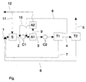
- the cracking furnace S becomes over Line 2 an olefin-containing mixed fraction drawn off and by means of the compressor C1 compressed to a pressure between 2.5 and 5 bar.
- an adsorptive or permeative first separation stage A1 a fraction containing H 2 , CH 4 and CO is separated from the olefin-containing mixed fraction.
- a second adsorptive or permeate separation stage A2 to which the fraction containing H 2 , CH 4 and CO is fed via line 9, a fraction rich in C 2+ components is separated from this and returned via line 10 to the compressor C1.
- the second separation stage A2 can thus ensure that the loss of C 2+ components in the heating gas is as low as possible.
- the fraction containing H 2 , CH 4 and CO drawn off from the second separation stage A2 is at least partially returned to the cracking furnace S as heating gas via line 11.
- the portion of the separated H 2 , CH 4 and CO containing fraction which is not fed to the cracking furnace S is withdrawn from the system via line 12.
- the light gases such as e.g. B. H 2 , CH 4 and CO through the membrane wall.
- the separation takes place at a pressure between 2 and 6 bar and a temperature between 0 and 100 ° C, preferably between 20 and 50 ° C.
- the fraction of the heavier gases is enriched on the pressure side.
- the first and / or second separation stage A1 or A2 is designed as an adsorption process, it is preferably designed as a pressure swing adsorption system. As a rule, a plurality of adsorbers are arranged in parallel, so that continuous operation is possible.
- the separation of the H 2 , CH 4 and CO-containing fraction from the olefin-containing mixed fraction is preferably carried out at an adsorption pressure between 1.0 and 10.0 bar, in particular between 2.5 and 5.0 bar, and at a temperature between 0 and 100 ° C, especially between 20 and 50 ° C. Suitable adsorbents have already been mentioned above.
- the regeneration of the loaded adsorption beds can - as also already mentioned - by lowering the pressure and / or evacuating the adsorption beds by means of at least one vacuum pump with post-compression and alternatively or additionally done by passing a purge gas.
- the olefin-containing mixed fraction attached to the selected adsorbents is then suctioned off, for example by means of a vacuum pump (not shown in the figure) and fed to a compressor C2 via line 3.
- the olefin-containing mixed fraction is compressed to a pressure of 10 to 60 bar, preferably 20 to 40 bar, and then fed to the separation process T1.
- the separation process T1 can be acid gas scrubbing, drying, hydrogenation, C 2 / C 3 separation, propane-propylene separation and C 3 / C 4+ separation and, if appropriate, others Separation steps include.
- the olefin-containing mixed fraction drawn off from the first separation stage A1 is conventionally further processed in the separation process T1 up to the C 2 / C 3 separation.
- This separation stage is divided into two. In the first part, a so-called unsharp C 1 / C 2 separation in the column head and a so-called sharp C 1 / C 2+ separation in the column bottom are carried out, and in the second part a sharp C 2 / C 3+ separation.
- the content of C 2 components in the copane fraction containing methane correlates with the pressure and the necessary cooling temperature. With these parameters, the cooling temperature can be selected so that propylene cooling is sufficient.
- the methane-rich fraction obtained in this way is returned via line 8 to the first separation stage A1.
- a C 2 / C 3+ separation takes place in the second separation column.
- a propane-rich fraction is returned from the C 3+ fraction before the cracking furnace S.
- an essentially pure C 2 fraction is withdrawn from the top of the separation column and fed to the second separation process T2 via line 4. In the present case, this is designed as a so-called C 2 splitter.
- the ethylene product fraction obtained in it is removed from the process via line 5, while the resulting ethane-rich fraction is likewise returned via line 6 to the cracking furnace S.
- the degree of separation for methane can be increased by the two-stage light gas separation, so that 35 to 40% of the total gas flow in the form of light gas are separated off before the main compressor, the acid gas wash, the dryer, the hydrogenation and the C 2 / C 3 separation. This means that these system components can also be dimensioned smaller. Ultimately, savings in investment costs of around 5 to 10% of the overall process can be expected.
- the inventive method does not require ethylene cooling and the amount of Subtracted from separation stage A1 containing olefin to be separated in the low-temperature section Mixed fraction is smaller than in the aforementioned methods, can also Refrigerant compressor capacity and corresponding reboiler heating capacity saved become.
- the olefin-containing stream can be increased by the amount of the light gases separated off by adsorption or permeation.
- the C 2 refrigeration cycle which has become superfluous for the separation task, the heat exchangers and the column for the C 1 / C 2 separation can be used in part or with little conversion effort for the additional C 2 separation.
- a so-called plant revamp should become much easier and cheaper.
Landscapes
- Chemical & Material Sciences (AREA)
- Oil, Petroleum & Natural Gas (AREA)
- Engineering & Computer Science (AREA)
- Chemical Kinetics & Catalysis (AREA)
- General Chemical & Material Sciences (AREA)
- Organic Chemistry (AREA)
- Organic Low-Molecular-Weight Compounds And Preparation Thereof (AREA)
Abstract
Die Erfindung betrifft ein Verfahren zum Gewinnen einer Ethylen-reichen Fraktion mittels kombinierter Adsorption und Rektifikation aus einer aus einem Spaltofen abgezogenen olefinhaltigen Mischfraktion, insbesondere aus einem Ethylenspaltgas, wobei eine im wesentlichen H2, CH4 und CO enthaltende Fraktion adsorptiv oder permeativ aus der olefinhaltigen Mischfraktion abgetrennt und anschließend die die restlichen Komponenten enthaltende Fraktion der Rektifikation zugeführt wird. Erfindungsgemäß erfolgt in der Rektifikation (T1) eine unscharfe C1/C2-Trennung und es wird wenigstens eine an C2-Komponenten abgereicherte Fraktion (8) vor die adsorptiv oder permeativ arbeitende Trennstufe (A1) zurückgeführt. Der adsorptiv oder permeativ arbeitenden Trennstufe (A1) kann wenigstens eine weitere adsorptiv oder permeativ arbeitende Trennstufe (A2) nachgeschaltet sein, wobei in dieser aus der in der ersten Trennstufe (A1) abgetrennten, H2, CH4 und CO enthaltenden Fraktion (9) eine an C2 Komponenten reiche Fraktion (10) abgetrennt wird. Das erfindungsgemäße Verfahren ermöglicht eine Verringerung der im kalten Trennteil zu verarbeitenden Gasströme, eine Einsparung der Tieftemperaturdemethanisierung und führt insgesamt zu einer Verringerung der Investitionskosten und Kältemittelverdichterleistung. <IMAGE>
Description
Die Erfindung betrifft ein Verfahren zum Gewinnen einer Ethylen-reichen Fraktion
mittels kombinierter Adsorption und Rektifikation aus einer aus einem Spaltofen
abgezogenen olefinhaltigen Mischfraktion, insbesondere aus einem Ethylenspaltgas,
wobei eine im wesentlichen H2, CH4 und CO enthaltende Fraktion adsorptiv oder
permeativ aus der olefinhaltigen Mischfraktion abgetrennt und anschließend die die
restlichen Komponenten enthaltende Fraktion der Rektifikation zugeführt wird.
Die Fraktionierung einer olefinhaltigen bzw. -reichen Mischfraktion ist bspw. bei
Ethylen-Anlagen, in denen aus dem Ethylenspaltgas Ethylen und/oder Propylen
gewonnen werden soll, erforderlich. Von besonderer Bedeutung für die Wirtschaftlichkeit
ist dabei die möglichst frühe Abtrennung der leichten Gase, wie z. B. H2, CH4
und CO, im Prozeßverlauf. Die genannten Komponenten werden nach ihrer Abtrennung
im wesentlichen für Heizzwecke verwendet. Der Abgabedruck des Heizgases aus
der Spaltgasfraktionierung beträgt 4 bis 6 bar. Die Ofenbrenner saugen die benötigte
Verbrennungsluft hierbei nach dem Treibstrahlprinzip selbst an. Die beschriebene
Verfahrensweise wird als "Front-end-Demethanisierung" bezeichnet.
Dazu gibt es verschiedene Methoden:
Bei der Tieftemperaturrektifikation wird das Ethylenspaltgas einem Druck zwischen 20
und 40 bar und einer Temperatur ≤ -100°C ausgesetzt, so daß Methan als Rücklaufkondensat
anfällt. Bei einem Absorptionsverfahren erfolgt die Auswaschung der
abzutrennenden C2- und C3-Komponenten z. B. durch Pentan als Waschflüssigkeit bei
einem Druck von 10 bis 30 bar und einer Temperatur zwischen -30 bis -50°C. Als
Variante wurde früher als Waschmittel für die Absorption von Ethylen und Propylen bei
Normaltemperatur und einem Druck von ca. 10 bar auch eine wässrige Kupferchlorid-Lösung
eingesetzt.
Als Adsorptionsverfahren wurde auch das sog. "Hypersorptionsverfahren" eingesetzt,
bei dem an einem Aktivkohlewanderbett bei einem Druck von 5 bis 10 bar die leichten
Komponenten aus dem Spaltgas abgetrennt werden. Die Aktivkohle wurde dabei
thermisch regeneriert.
Die Ethylen- und Propylenreingewinnung, sowie die C2/C3-Trennung erfolgen bei den
zum Stand der Technik zählenden Verfahren mittels Rektifikation bei einem Druck
zwischen 20 und 40 bar und einer Temperatur zwischen 20 °C bei Propylen und bis zu
-60°C bei der C2/C3-Trennung.
Im Entwicklungsstadium befinden sich derzeit auch Adsorptionsverfahren zur Alkenabtrennung
und/oder Reingewinnung, wobei alkenselektive Adsorbentien eingesetzt
werden. Allerdings sind die dabei erreichten Produktreinheiten und -ausbeuten noch
nicht zufriedenstellend.
Aus der DE-A-198 24 575 ist ein Verfahren zum Abtrennen einer im wesentlichen H2,
CH4 und CO enthaltenden Fraktion aus einer aus einem Spaltofen abgezogenen
olefinhaltigen Mischfraktion, insbesondere aus einem Ethylenspaltgas, bekannt. Bei
diesem Verfahren wird eine H2, CH4 und CO enthaltende Fraktion adsorptiv oder
permeativ aus der olefinhaltigen Mischfraktion abgetrennt. Des weiteren werden bei
dieser Verfahrensweise Ofenbrenner verwendet, die für niedrige Brenngasvordrücke
geeignet sind.
Nachteilig bei dem in der DE-A-198 24 575 beschriebenen Verfahren ist jedoch, daß
der CH4-Abtrenngrad bei einem vertretbarem Verlust an C2-Komponenten in das
Heizgas nur zwischen 50 und 60 % liegt. Dadurch wird zwar eine Reduzierung des
weiterzubehandelnden Gasstromes im kalten Teil der Rektifikation und eine Anhebung
der Taupunkte erreicht, jedoch ist weiterhin ein Tieftemperaturprozeß für die C1/C2-Trennung
erforderlich.
Aufgabe der vorliegenden Erfindung ist es, ein Verfahren zum Gewinnen einer Ethylenreichen
Fraktion mittels einer kombinierten Adsorption und Rektifikation aus einer aus
einem Spaltofen abgezogenen olefinhaltigen Mischfraktion, insbesondere aus einem
Ethylenspaltgas, anzugeben, das eine Reduzierung der Betriebs- und Investitionskosten
ermöglicht. Insbesondere soll die den der adsorptiv oder permeativ arbeitenden
Trennstufe nachfolgenden Verfahrensschritten zugeführte Menge leichter Gase verringert
und auf diese Weise der Molanteil bzw. der Partialdruck der zu kondensierenden
Komponenten erhöht werden. Ferner soll die erforderliche Kältemittelverdichterleistung
reduziert werden.
Dies wird erfindungsgemäß dadurch erreicht, daß in der der adsorptiv oder permeativ
arbeitenden Trennstufe nachgeschalteten Rektifikation eine unscharfe C1/C2-Trennung
erfolgt und wenigstens eine an C2-Komponenten abgereicherte Fraktion vor die
adsorptive Trennstufe zurückgeführt wird.
Der Begriff "unscharfe Trennung" wird weiter unten erläutert werden.
Eine vorteilhafte Ausgestaltung des erfindungsgemäßen Verfahrens ist dadurch
gekennzeichnet, daß der adsorptiv oder permeativ arbeitenden Trennstufe wenigstens
eine weitere adsorptiv oder permeativ arbeitende Trennstufe nachgeschaltet ist.
Mittels dieser Ausgestaltung kann in der ersten Trennstufe ein höherer Durchbruch von
C2-Komponenten zugelassen werden, da der Anteil an C2-Komponenten in der zweiten
Stufe adsorbiert wird. Diese an C2-Komponenten reiche Fraktion wird aus der zweiten
Trennstufe abgesaugt, verdichtet und vor die erste adsorptiv oder permeativ arbeitende
Trennstufe zurückgeführt.
Mit dem höheren Durchbruch an C2-Komponenten in der ersten Stufe erreicht man
zugleich einen höheren Abtrenngrad für die Leichtgase im Bereich von 80 bis 90 % für
Methan. Die an Leichtgasen arme Fraktion wird in den kalten Teil zur rektifikatorischen
Trennung weitergeleitet.
Bei dem erfindungsgemäßen Verfahren kann über den zulässigen Anteil an C2-Komponenten
im Leichtgas die Kopftemperatur in der Kolonne gewählt werden.
Das erfindungsgemäße Verfahren in vorteilhafter Weise weiterbildend wird vorgeschlagen,
daß der adsorptiv oder permeativ arbeitenden Trennstufe wenigstens eine
weitere adsorptiv oder permeativ arbeitende Trennstufe nachgeschaltet ist, in der aus
der abgetrennten, H2, CH4 und CO enthaltenden Fraktion eine an C2+-Komponenten
reiche Fraktion abgetrennt wird.
Mittels dieser Ausgestaltung des erfindungsgemäßen Verfahrens können die Verluste
an C2-Komponenten in die H2, CH4 und CO enthaltende Fraktion und damit in das
Heizgas minimiert werden. Vorzugsweise wird die an C2-Komponenten reiche Fraktion
deshalb vor die erste adsorptiv oder permeativ arbeitende Trennstufe zurückgeführt.
Eine weitere vorteilhafte Ausgestaltung des erfindungsgemäßen Verfahrens ist
dadurch gekennzeichnet, daß die H2, CH4 und CO enthaltende Fraktion zumindest
teilweise in den Spaltofen als Heizgas zurückgeführt wird. Dabei kommen vorteilhaft
sogenannte nichtselbstansaugende Ofenbrenner zum Einsatz. Diese haben den
Vorteil, daß bei ihrer Verwendung ein Brenngasvordruck von ca. 1,5 bis ca. 1,7 bar
ausreichend ist.
Entsprechend dem erfindungsgemäßen Verfahren wird die H2, CH4 und CO
enthaltende Fraktion mittels eines Adsorptionsprozesses, vorzugsweise eines
Druckwechseladsorptionsprozesses, oder eines Membranverfahrens aus der
olefinhaltigen Mischfraktion abgetrennt.
Die Abtrennung der H2, CH4 und CO enthaltenden Fraktion mittels eines Membranverfahrens
hat den Vorteil, daß die olefinhaltige Fraktion druckseitig anfällt und auf ein
Absaugen sowie Wiederverdichten verzichtet werden kann. Der Verfahrensdruck kann
dabei so gewählt werden, daß die leichten Gase als Permeat bereits bei einem
geeigneten Brenngasvordruck anfallen.
Es hat sich als zweckmäßig erwiesen, wenn entsprechend einer weiteren Ausgestaltung
des erfindungsgemäßen Verfahrens - im Falle des Vorsehens von mindestens
zwei Trennstufen - wenigstens eine der Trennstufen als ein Druckwechseladsorptionsprozeß
ausgeführt ist.
Eine weitere vorteilhafte Ausgestaltung des erfindungsgemäßen Verfahrens besteht
darin, daß als erste Trennstufe zur Trennung zwischen C1-- und C2+-Komponenten ein
Membrantrennprozeß eingesetzt wird. Der durch die Membran tretende Anteil an
C2+-Komponenten wird durch die nachfolgende Adsorptionsstufe zurückgehalten,
mittels einer Vakuumpumpe abgesaugt und verdichtet.
Die an C2+-Komponenten reichen Fraktionen aus der Membran- sowie der Adsorptionsstufe
werden gemäß einer ersten Alternative zusammengeführt und auf den für die
nachfolgende Rektifikation erforderlichen Druck nachverdichtet. Diese Verfahrensweise
hat den Vorteil, daß nur ein Teil der an C2+-Komponenten reichen Fraktion vom
Adsorbens abgesaugt und ein zweites Mal auf den für die Leichtgasabtrennung benötigten
Druck von 2 bis 5 bar verdichtet werden muß. Alternativ hierzu kann die in der
der Membranstufe nachgeschalteten Adsorptionsstufe anfallende C2+-Komponenten
reichen Fraktion auch vor die Membranstufe zurückgeführt werden.
Eine vorteilhafte Ausgestaltung des erfindungsgemäßen Verfahrens ist dadurch
gekennzeichnet, daß die adsorptive Abtrennung der H2, CH4 und CO enthaltenden
Fraktion bei einem Adsorptionsdruck zwischen 1,0 und 10,0 bar, vorzugsweise
zwischen 2,5 und 5,0 bar, und einer Temperatur von 0 bis 100 °C, vorzugsweise von
20 bis 50 °C erfolgt.
Als Adsorptionsmittel können Silikagele, Alugele, Aktivkohlematerialien und/oder
Zeolithe verwendet werden. Um deren Selektivität für Alkene zu erhöhen, empfiehlt es
sich, die Adsorbentien mit geeigneten Ionen, wie bspw. Cu+- und/oder Cd++-Ionen, zu
dotieren. Die Regenerierung der beladenen Adsorptionsbetten kann durch Evakuieren
der Adsorptionsbetten mittels wenigstens einer Vakuumpumpe und/oder mittels
Überleiten eines Spülgases erfolgen.
Das erfindungsgemäße Verfahren sowie weitere Ausgestaltungen desselben seien im
folgenden anhand des in der Figur dargestellten Ausführungsbeispiels näher erläutert.
Über Leitung 1 wird einem Spaltofen S eine Kohlenwasserstoffreiche Einsatzfraktion,
die bspw. aus einer Erdölraffinerie stammt, zugeführt. Bei Großanlagen werden im
Regelfall mehrere Spaltöfen S parallel betrieben. Aus dem Spaltofen S wird über
Leitung 2 eine olefinhaltige Mischfraktion abgezogen und mittels des Verdichters C1
auf einen Druck zwischen 2,5 und 5 bar komprimiert.
In einer adsorptiven oder permeativen ersten Trennstufe A1 wird aus der olefinhaltigen
Mischfraktion eine H2, CH4 und CO enthaltende Fraktion abgetrennt. In einer zweiten
adsorptiv oder permeativ arbeitenden Trennstufe A2, der die H2, CH4 und CO enthaltende
Fraktion über Leitung 9 zugeführt wird, wird aus dieser eine an C2+-Komponenten
reiche Fraktion abgetrennt und über Leitung 10 vor den Kompressor C1 zurückgeführt.
Mittels der zweiten Trennstufe A2 kann somit gewährleistet werden, daß der
Verlust an C2+-Komponenten in das Heizgas so gering als möglich ist.
Die aus der zweiten Trennstufe A2 abgezogene H2, CH4 und CO enthaltende Fraktion
wird über Leitung 11 zumindest teilweise in den Spaltofen S als Heizgas zurückgeführt.
Derjenige Teil der abgetrennten H2, CH4 und CO enthaltenden Fraktion, der nicht dem
Spaltofen S zugeführt wird, wird über Leitung 12 aus der Anlage abgezogen.
Bei Ausführung der ersten Trennstufe A1 als Membrananlage diffundieren überwiegend
die leichten Gase wie z. B. H2, CH4 und CO durch die Membranwand. Die Abtrennung
erfolgt bei einem Druck zwischen 2 und 6 bar und einer Temperatur zwischen
0 und 100°C, vorzugsweise zwischen 20 und 50 °C. Die Fraktion der schwereren Gase
wird hierbei auf der Druckseite angereichert.
Bei Ausführung der ersten und/oder zweiten Trennstufe A1 bzw. A2 als Adsorptionsprozeß
ist diese vorzugsweise als Druckwechseladsorptionsanlage ausgebildet Dabei
werden im Regelfall mehrere Adsorber parallel angeordnet, so daß ein kontinuierlicher
Betrieb möglich ist. Die Abtrennung der H2, CH4 und CO enthaltenden Fraktion aus der
olefinhaltigen Mischfraktion erfolgt vorzugsweise bei einem Adsorptionsdruck zwischen
1,0 und 10,0 bar, insbesondere zwischen 2,5 und 5,0 bar, sowie bei einer Temperatur
zwischen 0 und 100°C, insbesondere zwischen 20 und 50 °C. Geeignete Adsorptionsmittel
wurden bereits oben genannt.
Die Regenerierung der beladenen Adsorptionsbetten kann - wie ebenfalls bereits
erwähnt - durch Druckabsenkung und/oder Evakuieren der Adsorptionsbetten mittels
wenigstens einer Vakuumpumpe mit Nachverdichtung sowie alternativ oder zusätzlich
mittels Überleiten eines Spülgases erfolgen.
Die an den gewählten Adsorptionsmitteln angelagerte olefinhaltige Mischfraktion wird
sodann bspw. mittels einer in der Figur nicht dargestellten Vakuumpumpe abgesaugt
und über Leitung 3 einem Verdichter C2 zugeführt. In diesem wird die olefinhaltige
Mischfraktion auf einen Druck von 10 bis 60 bar, vorzugsweise von 20 bis 40 bar
verdichtet und anschließend dem Trennprozeß T1 zugeführt. Abhängig von der
Zusammensetzung der olefinhaltigen Mischfraktion sowie deren weiteren Verwendungszweck
kann der Trennprozeß T1 eine Sauergaswäsche, eine Trocknung, eine
Hydrierung, eine C2/C3-Trennung, eine Propan-Propylentrennung sowie eine C3/C4+-Trennung
und gegebenenfalls weitere Trennschritte umfassen.
Im vorliegenden Falle wird die aus der ersten Trennstufe A1 abgezogene olefinhaltige
Mischfraktion in dem Trennprozeß T1 konventionell bis zu der C2/C3-Trennung weiterbehandelt.
Diese Trennstufe ist zweigeteilt. In ihr wird im ersten Teil eine sog.
unscharfe C1/C2-Trennung im Kolonnenkopf sowie eine sog. scharfe C1/C2+-Trennung
im Kolonnensumpf und im zweiten Teil eine scharfe C2/C3+-Trennung durchgeführt.
Bei einer unscharfen Trennung einer zweikomponentigen Fraktion mit den Komponenten
A (Kopfprodukt) und B (Sumpfprodukt) liegt der Anteil der Komponente B in dem an
der Komponente A reichen Kopfprodukt im Bereich von bspw. 10 bis 50 %, während
der Anteil der Komponente A in dem an der Komponente B reichen Sumpfprodukt im
ppm-Bereich liegt. Bei einer scharfen Trennung liegt der Anteil der Komponente B in
dem an der Komponente A reichen Kopfprodukt im ppm Bereich und umgekehrt.
Am Kopf der ersten Trennkolonne erfolgt eine unscharfe C1-/C2-Trennung. Der Gehalt
an C2-Komponenten in der Methan-haltigen Kopifraktion korreliert mit dem Druck und
der notwendigen Kühltemperatur. Durch diese Parameter kann die Kühltemperatur so
gewählt werden, daß Propylenkälte ausreichend ist. Die so gewonnene Methan-reiche
Fraktion wird über Leitung 8 vor die erste Trennstufe A1 zurückgeführt.
In der zweiten Trennkolonne erfolgt eine C2/C3+-Trennung. Aus der C3+-Fraktion wird
nach der Propan/Propylentrennung über Leitung 7 eine Propan-reiche Fraktion vor den
Spaltofen S zurückgeführt. Zusätzlich wird aus dem Kopf der Trennkolonne eine im
wesentlichen reine C2-Fraktion abgezogen und über Leitung 4 dem zweiten Trennprozeß
T2 zugeführt. Dieser ist im vorliegenden Falle als ein sog. C2-Splitter ausgeführt.
Die in ihm gewonnene Ethylen-Produktfraktion wird über Leitung 5 aus dem Verfahren
abgeführt, während die anfallende Ethan-reiche Fraktion über Leitung 6 ebenfalls vor
den Spaltofen S zurückgeführt wird.
Die beschriebene C2/C3-Trennung des Trennprozesses T1 könnte hierbei sowohl in
einer als auch in zwei separaten Trennkolonnen erfolgen.
Die beschriebene Verfahrensführung hat gegenüber dem in der DE-A-198 24 575
offenbarten Verfahren den Vorteil, daß der gesamte Tieftemperaturteil nach der
konventionellen C2/C3-Trennung bis zum C2-Splitter mit C2-Kältkreislauf und Coldbox
entfällt.
Durch die zweistufige Leichtgasabtrennung kann der Abtrenngrad für Methan erhöht
werden, so daß 35 bis 40 % des Gesamtgasstromes in Form von Leichtgas vor dem
Hauptverdichter, der Sauergaswäsche, dem Trockner, der Hydrierung sowie der C2/C3-Trennung
abgetrennt werden. Damit können auch diese Anlagenteile kleiner dimensioniert
werden. Letztendlich ist eine Einsparung bei den Investitionskosten in einer
Größenordnung von ca. 5 bis 10 % des Gesamtprozesses zu erwarten.
Da das erfindungsgemäße Verfahren keine Ethylenkälte benötigt und die Menge der
aus der Trennstufe A1 abgezogenen, im Tieftemperaturteil zu trennenden olefinhaltigen
Mischfraktion kleiner ist als bei den vorgenannten Verfahren, können zudem
Kältemittelverdichterleistung und entsprechende Reboilerheizleistung eingespart
werden.
Weitere Vorteile ergeben sich bei einer Erweiterung bzw. einem Umbau bestehender
Ethylenanlagen. Durch die Realisierung des erfindungsgemäßen Verfahrens zum
Gewinnen einer Ethylen-reichen Fraktion kann der olefinhaltige Strom um den Betrag
der adsorptiv oder permeativ abgetrennten Leichtgase vergrößert werden. Der für die
Trennaufgabe überflüssig gewordene C2-Kältekreislauf, die Wärmetauscher und die
Kolonne für die C1/C2-Trennung können teilweise oder mit geringem Umbauaufwand
zur zusätzlichen C2-Trennung verwendet werden. Somit dürfte auch ein sog. Anlagenrevamp
wesentlich einfacher und preisgünstiger werden.
Das erfindungsgemäße Verfahren zum Gewinnen einer Ethylen-reichen Fraktion
mittels kombinierter Adsorption und Rektifikation ist insbesondere auch bei der
Ethylenreinigung aus der Ethandehydrierung oder bei der Ethylengewinnung aus
einem FCC-Gas anwendbar.
Claims (10)
- Verfahren zum Gewinnen einer Ethylen-reichen Fraktion mittels kombinierter Adsorption und Rektifikation aus einer aus einem Spaltofen abgezogenen olefinhaltigen Mischfraktion, insbesondere aus einem Ethylenspaltgas, wobei eine im wesentlichen H2, CH4 und CO enthaltende Fraktion adsorptiv oder permeativ aus der olefinhaltigen Mischfraktion abgetrennt und anschließend die die restlichen Komponenten enthaltende Fraktion der Rektifikation zugeführt wird, dadurch gekennzeichnet, daß in der Rektifikation (T1) eine unscharfe C1/C2-Trennung erfolgt und wenigstens eine an C2-Komponenten abgereicherte Fraktion (8) vor die adsorptiv oder permeativ arbeitende Trennstufe (A1) zurückgeführt wird.
- Verfahren nach Anspruch 1, dadurch gekennzeichnet daß der adsorptiv oder permeativ arbeitenden Trennstufe (A1) wenigstens eine weitere adsorptiv oder permeativ arbeitende Trennstufe (A2) nachgeschaltet ist, in der aus der in der ersten Trennstufe (A1) abgetrennten, H2, CH4 und CO enthaltenden Fraktion (9) eine an C2 Komponenten reiche Fraktion (10) abgetrennt wird.
- Verfahren nach Anspruch 2, dadurch gekennzeichnet, daß die an C2 -Komponenten reiche Fraktion (10) aus der zweiten Trennstufe (A2) vor die erste adsorptiv oder permeativ arbeitende Trennstufe (A1) zurückgeführt wird.
- Verfahren nach einem der vorhergehenden Ansprüche, dadurch gekennzeichnet, daß die H2, CH4 und CO enthaltende Fraktion (9, 11) zumindest teilweise in oder vor den Spaltofen (S) zurückgeführt wird.
- Verfahren nach einem der vorhergehenden Ansprüche, dadurch gekennzeichnet, daß der Spaltofen (S) mit wenigstens einem nichtselbstansaugenden Ofenbrenner betrieben wird.
- Verfahren nach einem der vorhergehenden Ansprüche, dadurch gekennzeichnet, daß wenigstens eine der Trennstufen (A1, A2) als ein Druckwechseiadsorptionsprozeß ausgeführt ist.
- Verfahren nach einem der vorhergehenden Ansprüche, dadurch gekennzeichnet, daß die adsorptive Abtrennung (A1) der H2, CH4 und CO enthaltenden Fraktion (3) bei einem Adsorptionsdruck zwischen 1,0 und 10,0 bar, vorzugsweise zwischen 2,5 und 5,0 bar, und einer Temperatur von 0 bis 100 °C, vorzugsweise von 20 bis 50 °C erfolgt.
- Verfahren nach einem der vorhergehenden Ansprüche, dadurch gekennzeichnet, daß die Regenerierung des oder der beladenen Adsorptionsbetten mittels wenigstens einer Vakuumpumpe und/oder Überleiten eines Spülgases erfolgt.
- Verfahren nach einem der vorhergehenden Ansprüche, dadurch gekennzeichnet, daß als Adsorptionsmittel Silikagele, Alugele, Aktivkohlematerialien und/oder Zeolithe verwendet werden.
- Verfahren nach Anspruch 9, dadurch gekennzeichnet, daß das verwendete Adsorptionsmittel mit Cu+-Ionen und/oder Cd++-Ionen dotiert ist.
Applications Claiming Priority (2)
| Application Number | Priority Date | Filing Date | Title |
|---|---|---|---|
| DE19903566 | 1999-01-29 | ||
| DE1999103566 DE19903566A1 (de) | 1999-01-29 | 1999-01-29 | Verfahren zum Gewinnen einer Ethylen-reichen Fraktion |
Publications (1)
| Publication Number | Publication Date |
|---|---|
| EP1024187A1 true EP1024187A1 (de) | 2000-08-02 |
Family
ID=7895805
Family Applications (1)
| Application Number | Title | Priority Date | Filing Date |
|---|---|---|---|
| EP00101793A Withdrawn EP1024187A1 (de) | 1999-01-29 | 2000-01-28 | Verfahren zum Gewinnen einer Ethylen-reichen Fraktion |
Country Status (2)
| Country | Link |
|---|---|
| EP (1) | EP1024187A1 (de) |
| DE (1) | DE19903566A1 (de) |
Cited By (5)
| Publication number | Priority date | Publication date | Assignee | Title |
|---|---|---|---|---|
| CN101732883B (zh) * | 2010-01-21 | 2012-05-30 | 天津天大天海化工新技术有限公司 | 用于芳烃溶剂油脱色的吸附精馏塔及其工艺方法 |
| WO2016020042A1 (de) * | 2014-08-07 | 2016-02-11 | Linde Aktiengesellschaft | Rückgewinnung von gasen, insbesondere permanentgasen, aus stoffströmen, insbesondere aus abgasströmen von polymerisationen |
| WO2018111535A1 (en) * | 2016-12-15 | 2018-06-21 | Chevron Phillips Chemical Company Lp | Membrane and pressure swing adsorption hybrid inru process |
| EP3456703A1 (de) * | 2017-09-13 | 2019-03-20 | Linde Aktiengesellschaft | Verfahren und anlage zur herstellung von ethylen |
| EP3940042A1 (de) * | 2020-07-17 | 2022-01-19 | Linde GmbH | Verfahren und anlage zur gewinnung von kohlenwasserstoffen |
Citations (4)
| Publication number | Priority date | Publication date | Assignee | Title |
|---|---|---|---|---|
| US4842718A (en) * | 1986-09-30 | 1989-06-27 | Shell Oil Company | Process for recovery of hydrocarbons from a fluid feed |
| US5245099A (en) * | 1992-07-22 | 1993-09-14 | Uop | PSA process for recovery or ethylene |
| US5814208A (en) * | 1994-09-30 | 1998-09-29 | Menon; Raghu K. | Hydrocarbon catalytic cracking process |
| DE19824575C1 (de) * | 1998-06-02 | 1999-11-11 | Linde Ag | Verfahren zum Abtrennen einer im wesentlichen H2, CH4 und CO enthaltenden Fraktion aus einer olefinhaltigen Mischfraktion |
-
1999
- 1999-01-29 DE DE1999103566 patent/DE19903566A1/de not_active Withdrawn
-
2000
- 2000-01-28 EP EP00101793A patent/EP1024187A1/de not_active Withdrawn
Patent Citations (4)
| Publication number | Priority date | Publication date | Assignee | Title |
|---|---|---|---|---|
| US4842718A (en) * | 1986-09-30 | 1989-06-27 | Shell Oil Company | Process for recovery of hydrocarbons from a fluid feed |
| US5245099A (en) * | 1992-07-22 | 1993-09-14 | Uop | PSA process for recovery or ethylene |
| US5814208A (en) * | 1994-09-30 | 1998-09-29 | Menon; Raghu K. | Hydrocarbon catalytic cracking process |
| DE19824575C1 (de) * | 1998-06-02 | 1999-11-11 | Linde Ag | Verfahren zum Abtrennen einer im wesentlichen H2, CH4 und CO enthaltenden Fraktion aus einer olefinhaltigen Mischfraktion |
Cited By (17)
| Publication number | Priority date | Publication date | Assignee | Title |
|---|---|---|---|---|
| CN101732883B (zh) * | 2010-01-21 | 2012-05-30 | 天津天大天海化工新技术有限公司 | 用于芳烃溶剂油脱色的吸附精馏塔及其工艺方法 |
| WO2016020042A1 (de) * | 2014-08-07 | 2016-02-11 | Linde Aktiengesellschaft | Rückgewinnung von gasen, insbesondere permanentgasen, aus stoffströmen, insbesondere aus abgasströmen von polymerisationen |
| US10092876B2 (en) | 2014-08-07 | 2018-10-09 | Linde Aktiengesellschaft | Recovery of gases, especially permanent gases, from streams of matter, especially from offgas streams from polymerizations |
| RU2687951C2 (ru) * | 2014-08-07 | 2019-05-16 | Линде Акциенгезелльшафт | Извлечение газов, в частности неконденсирующихся газов, из массовых потоков, в частности из потоков отходящих газов с процессов полимеризации |
| US10449480B2 (en) | 2016-12-15 | 2019-10-22 | Chevron Phillips Chemical Company Lp | Membrane and pressure swing adsorption hybrid INRU process |
| WO2018111535A1 (en) * | 2016-12-15 | 2018-06-21 | Chevron Phillips Chemical Company Lp | Membrane and pressure swing adsorption hybrid inru process |
| US11058987B2 (en) | 2016-12-15 | 2021-07-13 | Chevron Phillips Chemical Company Lp | Membrane and pressure swing adsorption hybrid INRU process |
| CN111094221A (zh) * | 2017-09-13 | 2020-05-01 | 林德股份公司 | 生产乙烯的方法和设备 |
| WO2019053122A1 (de) * | 2017-09-13 | 2019-03-21 | Linde Aktiengesellschaft | Verfahren und anlage zur herstellung von ethylen |
| EP3456703A1 (de) * | 2017-09-13 | 2019-03-20 | Linde Aktiengesellschaft | Verfahren und anlage zur herstellung von ethylen |
| EA038467B1 (ru) * | 2017-09-13 | 2021-09-01 | Линде Акциенгезельшафт | Способ получения этилена |
| US11130722B2 (en) | 2017-09-13 | 2021-09-28 | Linde Aktiengesellschaft | Method and plant for producing ethylene |
| AU2018333572B2 (en) * | 2017-09-13 | 2023-04-20 | Linde Aktiengesellschaft | Method and plant for producing ethylene |
| CN111094221B (zh) * | 2017-09-13 | 2023-06-09 | 林德股份公司 | 生产乙烯的方法和设备 |
| EP3940042A1 (de) * | 2020-07-17 | 2022-01-19 | Linde GmbH | Verfahren und anlage zur gewinnung von kohlenwasserstoffen |
| WO2022013424A1 (de) | 2020-07-17 | 2022-01-20 | Linde Gmbh | Verfahren und anlage zur gewinnung von kohlenwasserstoffen |
| CN115812095A (zh) * | 2020-07-17 | 2023-03-17 | 林德有限公司 | 用于获得烃的工艺及设备 |
Also Published As
| Publication number | Publication date |
|---|---|
| DE19903566A1 (de) | 2000-08-03 |
Similar Documents
| Publication | Publication Date | Title |
|---|---|---|
| DE69618711T2 (de) | Verfahren zur integrierten Lufttrennung | |
| DE69308678T2 (de) | Herstellung von Wasserstoff und Kohlenoxyd durch partielle Oxydierung von Kohlenwasserstoff | |
| DE69305420T2 (de) | Verfahren zur Auftrennung von Kohlenwasserstoffgemischen | |
| DE69116781T2 (de) | Integriertes Verfahren zur Herstellung von Kohlenoxyd | |
| DE60109522T2 (de) | Verfahren zur Reinigung von Gasen | |
| DE3783478T2 (de) | Zurueckgewinnung von argon. | |
| DE69526042T2 (de) | Entfernung von Kohlendioxid aus Gasströmen | |
| DE69131839T2 (de) | Duplexadsorptionsprozess | |
| EP0053837B1 (de) | Adsorptionsverfahren und Anlage zur Durchführung des Verfahrens | |
| DE69316954T2 (de) | Reinigung von Sauerstoff durch Adsorption | |
| EP0012986A1 (de) | Verfahren zum Abtrennen und Gewinnen gasförmiger Komponenten aus einem Gasgemisch durch physikalische Wäsche | |
| DE1272891B (de) | Verfahren zum Reinigen von Gasen oder Daempfen | |
| EP0185253B1 (de) | Verfahren und Vorrichtung zur Gewinnung von C2+- oder von C3+-Kohlenwasserstoffen | |
| DE69511805T2 (de) | Lufttrennung | |
| RU2681910C2 (ru) | Способ извлечения метана из потока газа, содержащего метан и этилен | |
| DE3247773C2 (de) | ||
| DE4200069C2 (de) | Verfahren und Vorrichtung zum Erzeugen von Rohneon | |
| DE60122098T3 (de) | Herstellung von Wasserstoff mittels Druckwechseladsorption durch Verwendung von einem Mehrschichtigen Adsorptionsbett | |
| DE69900656T2 (de) | Verfahren zur Trennung von Alkenen und Alkanen | |
| DE2460515A1 (de) | Verfahren und vorrichtung zur entfernung von verunreinigungen aus solche enthaltenden tiefsiedenden gasen | |
| DE60307986T2 (de) | Behandlung von wasserstoff/kohlenwasserstoff mischungen mit bei hohem druck regenerierten adsorptionmitteln | |
| DE69004393T2 (de) | Lufttrennung. | |
| DE19903566A1 (de) | Verfahren zum Gewinnen einer Ethylen-reichen Fraktion | |
| DE69507227T2 (de) | Verfahren zur herstellung eines gases mittels adsorption | |
| EP0015413A1 (de) | Druckwechseladsorptionsverfahren zur Zerlegung oder Reinigung von Gasgemischen |
Legal Events
| Date | Code | Title | Description |
|---|---|---|---|
| PUAI | Public reference made under article 153(3) epc to a published international application that has entered the european phase |
Free format text: ORIGINAL CODE: 0009012 |
|
| AK | Designated contracting states |
Kind code of ref document: A1 Designated state(s): AT BE CH CY DE DK ES FI FR GB GR IE IT LI LU MC NL PT SE |
|
| AX | Request for extension of the european patent |
Free format text: AL;LT;LV;MK;RO;SI |
|
| 17P | Request for examination filed |
Effective date: 20000610 |
|
| AKX | Designation fees paid |
Free format text: AT BE CH CY DE DK ES FI FR GB GR IE IT LI LU MC NL PT SE |
|
| STAA | Information on the status of an ep patent application or granted ep patent |
Free format text: STATUS: THE APPLICATION IS DEEMED TO BE WITHDRAWN |
|
| 18D | Application deemed to be withdrawn |
Effective date: 20030801 |