EP1024032A2 - Pneumatic tire - Google Patents
Pneumatic tire Download PDFInfo
- Publication number
- EP1024032A2 EP1024032A2 EP00300660A EP00300660A EP1024032A2 EP 1024032 A2 EP1024032 A2 EP 1024032A2 EP 00300660 A EP00300660 A EP 00300660A EP 00300660 A EP00300660 A EP 00300660A EP 1024032 A2 EP1024032 A2 EP 1024032A2
- Authority
- EP
- European Patent Office
- Prior art keywords
- land portion
- tire
- pneumatic tire
- land
- transverse direction
- Prior art date
- Legal status (The legal status is an assumption and is not a legal conclusion. Google has not performed a legal analysis and makes no representation as to the accuracy of the status listed.)
- Granted
Links
Images

Classifications
-
- B—PERFORMING OPERATIONS; TRANSPORTING
- B60—VEHICLES IN GENERAL
- B60C—VEHICLE TYRES; TYRE INFLATION; TYRE CHANGING; CONNECTING VALVES TO INFLATABLE ELASTIC BODIES IN GENERAL; DEVICES OR ARRANGEMENTS RELATED TO TYRES
- B60C11/00—Tyre tread bands; Tread patterns; Anti-skid inserts
- B60C11/0083—Tyre tread bands; Tread patterns; Anti-skid inserts characterised by the curvature of the tyre tread
-
- B—PERFORMING OPERATIONS; TRANSPORTING
- B60—VEHICLES IN GENERAL
- B60C—VEHICLE TYRES; TYRE INFLATION; TYRE CHANGING; CONNECTING VALVES TO INFLATABLE ELASTIC BODIES IN GENERAL; DEVICES OR ARRANGEMENTS RELATED TO TYRES
- B60C11/00—Tyre tread bands; Tread patterns; Anti-skid inserts
-
- B—PERFORMING OPERATIONS; TRANSPORTING
- B60—VEHICLES IN GENERAL
- B60C—VEHICLE TYRES; TYRE INFLATION; TYRE CHANGING; CONNECTING VALVES TO INFLATABLE ELASTIC BODIES IN GENERAL; DEVICES OR ARRANGEMENTS RELATED TO TYRES
- B60C11/00—Tyre tread bands; Tread patterns; Anti-skid inserts
- B60C11/01—Shape of the shoulders between tread and sidewall, e.g. rounded, stepped or cantilevered
-
- B—PERFORMING OPERATIONS; TRANSPORTING
- B60—VEHICLES IN GENERAL
- B60C—VEHICLE TYRES; TYRE INFLATION; TYRE CHANGING; CONNECTING VALVES TO INFLATABLE ELASTIC BODIES IN GENERAL; DEVICES OR ARRANGEMENTS RELATED TO TYRES
- B60C11/00—Tyre tread bands; Tread patterns; Anti-skid inserts
- B60C11/03—Tread patterns
- B60C11/0306—Patterns comprising block rows or discontinuous ribs
- B60C11/0309—Patterns comprising block rows or discontinuous ribs further characterised by the groove cross-section
-
- B—PERFORMING OPERATIONS; TRANSPORTING
- B60—VEHICLES IN GENERAL
- B60C—VEHICLE TYRES; TYRE INFLATION; TYRE CHANGING; CONNECTING VALVES TO INFLATABLE ELASTIC BODIES IN GENERAL; DEVICES OR ARRANGEMENTS RELATED TO TYRES
- B60C11/00—Tyre tread bands; Tread patterns; Anti-skid inserts
- B60C11/03—Tread patterns
- B60C11/04—Tread patterns in which the raised area of the pattern consists only of continuous circumferential ribs, e.g. zig-zag
- B60C11/042—Tread patterns in which the raised area of the pattern consists only of continuous circumferential ribs, e.g. zig-zag further characterised by the groove cross-section
-
- B—PERFORMING OPERATIONS; TRANSPORTING
- B60—VEHICLES IN GENERAL
- B60C—VEHICLE TYRES; TYRE INFLATION; TYRE CHANGING; CONNECTING VALVES TO INFLATABLE ELASTIC BODIES IN GENERAL; DEVICES OR ARRANGEMENTS RELATED TO TYRES
- B60C11/00—Tyre tread bands; Tread patterns; Anti-skid inserts
- B60C11/03—Tread patterns
- B60C11/13—Tread patterns characterised by the groove cross-section, e.g. for buttressing or preventing stone-trapping
-
- B—PERFORMING OPERATIONS; TRANSPORTING
- B60—VEHICLES IN GENERAL
- B60C—VEHICLE TYRES; TYRE INFLATION; TYRE CHANGING; CONNECTING VALVES TO INFLATABLE ELASTIC BODIES IN GENERAL; DEVICES OR ARRANGEMENTS RELATED TO TYRES
- B60C11/00—Tyre tread bands; Tread patterns; Anti-skid inserts
- B60C11/01—Shape of the shoulders between tread and sidewall, e.g. rounded, stepped or cantilevered
- B60C2011/013—Shape of the shoulders between tread and sidewall, e.g. rounded, stepped or cantilevered provided with a recessed portion
Definitions
- the present invention relates to a pneumatic tire used for trucks, buses or the like, and in particular, to a pneumatic tire having excellent uneven wear resistance.
- Land portions are portions formed by dividing the ground-contact surface of the tire by circumferential direction grooves or lug grooves.
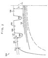
- FIG. 2 A conventional pneumatic tire to which a measure against uneven wear has been applied is illustrated in Fig. 2.
- a center rib 106, a second rib 108, and a shoulder rib 110 are formed from an equatorial plane CL along the tire transverse direction, by circumferential direction grooves 104 formed in the surface of a tread 102.
- a tire radial direction distance (step) H between, on the one hand, a tire transverse direction outer contour line L3 (including the imaginary extension line) along the ground-contact surface, and on the other hand, the ground-contact surface of the shoulder rib 110, is formed so as to be constant.
- the shoulder rib 110 has the step H in the direction in which the radius contracts, with respect to the second rib 108 and the center rib 106. Accordingly, when a heavy load is applied to the pneumatic tire 100, the ground contact pressure on the shoulder rib 110 is relatively small, and the ground contact pressure on the center rib 106 and the second rib 108 is equalized. Thus, uneven wear (second rib punch, center rib punch) of the center rib 106 and the second rib 108 can be prevented.
- the step H is set to be no more than 0.40 times the tread thickness D at the equatorial plane CL.
- the tread thickness D at the equatorial plane CL is the distance, in the radial direction of the tire, from the ground contact surface to the uppermost belt layer 112).
- this step H is constant along the tire transverse direction at the shoulder rib 110, there is also a step H at the tire transverse direction outer end side of the shoulder rib. Accordingly, when a usual load to a light load is applied to the pneumatic tire 100, the ground contact pressure becomes even lower at the shoulder rib, at which the ground contact pressure is relatively low as compared to the other portions of the tread when a light load is applied. A drawback arises in that the uneven wear at the outer end side of the shoulder rib is promoted.
- an object of the present invention is to provide a pneumatic tire which exhibits superior uneven wear resistance in all of the land portions formed on the tire.
- a pneumatic tire comprising a tread surface having a plurality of grooves extending along a circumferential direction of the pneumatic tire, wherein the grooves define a plurality of land portions the land portions includes; a first land portion which, among the plurality of land portions, is formed the furthest toward a tire transverse direction outer side; and a second land portion formed adjacent to the first land portion in a tire transverse direction, wherein given that a distance, along a tire radial direction, from an imaginary extension line of a tire transverse direction outer contour line along a ground contact surface at the second land portion to a tire transverse direction inner side end portion of the first land portion is H1, that a distance, along a tire radial direction, from an imaginary extension line of a tire transverse direction outer contour line along a ground contact surface at the second land portion to a tire transverse direction outer side end portion of the first land portion is H2, and that a direction toward a tire center is positive, the
- a step (tire radial direction distance H1) is provided between the first land portion and the second land portion.
- the ground contact pressure at the first land portion is lowered relatively, and the ground contact pressures at the first land portion and the second land portion are equalized. Accordingly, even in a case in which a heavy load (a load exceeding 100% when a standard load is considered to be 100%) is applied to the tire and the ground contact pressure is greatest (compared to other portions of the tire) at the tire transverse direction end portion, i.e., the first land portion, uneven wear at the land portion at the equatorial plane side of the second land portion can be reliably prevented.
- the step H1 which is between an imaginary extension line of the outer contour line of the second land portion and a tire transverse direction inner side (second land portion side) end portion of the first land portion
- the step H2 which is between an imaginary extension line of the outer contour line of the second land portion and a tire transverse direction outer side end portion of the first land portion
- the step between the first land portion and the second land portion uneven wear can be prevented from occurring at the second land portion when a heavy load is applied. Further, by forming the step between the outer contour line and the first land portion so as to decrease from the inner side end portion of the first land portion toward the outer side end portion thereof, uneven wear of the first land portion, which may be great due to the step when a light load is applied, is suppressed.
- the loud portions further include a third land portion formed at a tire transverse direction inner side of the second land portion, and given that a tire radial direction depth of a circumferential direction groove formed between the second land portion and the third land portion is D, the tire radial direction distane H1 falls within the range 0 ⁇ H1 ⁇ 0.3D.
- a first land portion the end portion of the second land portion is chamfered.
- the first land portion side end portion of the second land portion can be prevented from protruding out and abutting the road surface. Therefore, uneven wear of this portion can be prevented.
- Fig. 1 is a tire transverse direction cross-sectional view of a crown portion of a pneumatic tire.
- a pneumatic tire 10 comprises plural belt layers 12 which are positioned at the crown portion of a carcass (not shown) (there are five belt layers 12 in the present embodiment), a tread portion 14 which is formed at the upper portion of the belt layers 12, and shoulder portions 16 which are formed so as to be continuous with the tire transverse direction end portions of the tread portion 14.
- the ground contact configuration at the tire transverse direction cross-section of the center rib 20 and the second rib 22 is along an arcuate outer contour line L1 having a radius R1 with the center being the tire inner side.
- the ground contact configuration at the tire transverse direction cross-section of the shoulder rib 24 is along an arcuate outer contour line L2 having a radius R2 with the center being the tire inner side.
- the point of intersection of the outer contour lines L1, L2 (including the imaginary extension lines) is at the tire transverse direction outer side of the shoulder rib 24.
- the tire radial direction distance (step) between the outer contour line L1 and the outer contour line L2 at the second rib 22 side end portion of the shoulder rib 24 (hereinafter called the “shoulder rib inner end portion") is H1.
- the tire radial direction distance (step) between the outer contour line L1 and the outer contour line L2 at the tire transverse direction outer side end portion of the shoulder rib 24 (hereinafter called the "shoulder rib outer end portion”) is H2. Comparing these two values, it can be seen that H1>H2. Namely, the shoulder rib 24 is formed such that the step decreases toward the outer end portion side thereof.
- the tire radial direction depth of the circumferential direction groove 18 formed between the center rib 20 and the center rib 22 is D. It is preferable that the step H1 is formed to fall in the range 0 ⁇ H1 ⁇ 0.3D. Further, it is preferable that the step H1 is 0.3 mm or less.
- step H1 is such that H1 ⁇ 0, i.e., if H1 is negative, when a heavy load is applied, the ground contact pressure at the shoulder rib (the first land portion) 24 will be even higher, and uneven wear will progress from the second rib 22 (second land portion) toward the center rib 20 (the land portion at the equatorial plane side).
- the step H1 exceeds 0.3D, the step is too large.
- the degree of rectangularity at the shoulder rib 24 inner end side will decrease relatively, and there is the possibility that uneven wear will be caused at this portion.
- the “degree of rectangularity” is the ratio (X1/X2) of the ground contact length (X1) at the shoulder rib inner end side to the ground contact length (X2) of the center rib 20 in a case in which the tire circumferential direction lengths (ground contact lengths) of the respective land portions are measured by using the footprint as the ground contact configuration of the tire.
- the outer contour lines L1, L2 are measurements, taken by a laser configuration measuring device, of the configuration at the time when the pneumatic tire 10 is mounted to a standard rim and is inflated to standard pressure (dual).
- standard in “standard rim” and “standard” in “standard pressure” are as defined by TRA (The Tire and Rim Association Inc.) or ETRTO (The European Tire and Rim Technical Organization).
- the steps H1, H2 between the outer contour line L1 and the outer contour line L2 are formed so as to decrease toward the shoulder rib 24 outer end portion side. Therefore, the ground contact pressure at the outer side end portion of the shoulder rib 24, which is where the ground contact pressure is lower than the other portions at the time a light load is applied, is higher than a case in which the steps are constant. Thus, the ground contact pressure is equalized from the center rib 20 to the shoulder rib 24. As a result, even though a step is provided between the shoulder rib 24 and the second rib 22, uneven wear of the shoulder rib (the first land portion) can be reliably suppressed.
- the point of intersection of the outer contour line L1 and the outer contour line L2 may be positioned above the shoulder rib 24 (between the inner end portion and the outer end portion), i.e., H2 may have a negative value. In this way, the ground contact pressure when a light load is applied is equalized even more in the tire transverse direction, and uneven wear in a vicinity of the outer side end portion of the shoulder rib 24 can be suppressed even more.
- shoulder rib side end portion of the second rib 22 is chamfered (e.g., chamfered at the curvature R3 as shown by the dashed line in Fig. 1), uneven wear of the shoulder rib side end portion of the second rib 22 can be suppressed even more.
- Example Tire was substantially similar to that of the tire of the above described embodiment (see Fig. 1) (with the shoulder rib side end portion of the second rib 22 being chamfered to R3). However, the point of intersection of the outer contour lines L1, L2 was positioned above the shoulder rib 24. Namely, the step H2 was negative.
- the configuration of the Comparative Example 1 Tire was a configuration in which there was no step between the second rib and the shoulder rib.
- the configuration of the Comparative Example 2 Tire was such that the steps were constant, in the same way as the tire configuration of the above-described conventional example (see Fig. 2).
- the tire size of each tire was 305/75R24.5.
- the configuration when the tire was mounted to a standard rim (9.00 ⁇ 24.5) and inflated to standard internal pressure (dual, 8.2 kgf/cm 2 ) was measured by a laser configuration measurement device and used as the outer contour configuration.
- the footprint with the tire inflated to standard internal pressure (dual) and with a load of 85% of standard load applied thereto was measured and used as the ground contact configuration.
- the tires were mounted to standard rims, filled to standard internal pressures, and run on an actual road with a with a usage load of 2800 kgf applied thereto.
- the uneven wear of the shoulder rib and the second rib were evaluated after running for 10,000 km, 30,000 km, 50,000 km, 100,000 km, and 150,000 km.
- the rim herein was a standard rim (or "approved rim” or “recommended rim”) corresponding to the size of the radial ply tire determined in accordance with standards.
- the internal pressure was the air pressure corresponding to the maximum load of a single wheel (maximum loadability) at an appropriate size determined in accordance with the following standards.
- the load was the maximum load of a single wheel (maximum loadability) at an appropriate size determined in accordance with the following standards.
- the Example Tire because a step was provided between the shoulder rib and the second rib, which was different than the Comparative Example 1 Tire, the Example Tire exhibited improved uneven wear resistance of the second rib. Further, in the Example Tire, the outer contour line of the second rib and the outer contour line of the shoulder rib intersected above the shoulder rib. It was confirmed that, due to that structure, the uneven wear resistance of the shoulder rib could also be maintained. Namely, by providing the step, the uneven wear resistance of the second rib improved. Due to the steps becoming smaller from the shoulder rib inner end portion toward the shoulder rib outer end portion, uneven wear of the shoulder rib which would be promoted by the step was suppressed.
- the present invention provides a pneumatic tire in which, when a heavy load is applied, uneven wear of the land portion at the equatorial plane side of the second rib can be prevented, and when a light load is applied, uneven wear of the tire transverse direction end portion side of the shoulder rib can be suppressed.
Landscapes
- Engineering & Computer Science (AREA)
- Mechanical Engineering (AREA)
- Tires In General (AREA)
Abstract
Description
| Comp. Ex. 2 | Example | Comp. Ex. 1 | |
| H1 | 1 | 1.2 | 0 |
| H2 | 1 | -0.3 | 0 |
| R1 | 660 | 660 | 660 |
| R2 | - | ∞ | - |
| R3 | - | 190 | - |
| On-Road Evaluation | Comp. Ex. 2 | Example | Comp. Ex. 1 |
| | 110 | 110 | 100 |
| shoulder rib | 90 | 100 | 100 |
Claims (20)
- A pneumatic tire comprising a tread surface having a plurality of grooves extending along a circumferential direction of the pneumatic tire, wherein the grooves define a plurality of land portions, said land portions including:a first land portion which, among the plurality of land portions, is formed the furthest toward a tire transverse direction outer side; anda second land portion formed adjacent to said first land portion in a tire transverse direction,
wherein giventhe relationship H1>H2 is established.that a distance, along a tire radial direction, from an imaginary extension line of a tire transverse direction outer contour line along a ground contact surface at said second land portion to a tire transverse direction inner side end portion of said first land portion is H1,that a distance, along a tire radial direction, from an imaginary extension line of a tire transverse direction outer contour line along a ground contact surface at said second land portion to a tire transverse direction outer side end portion of said first land portion is H2, andthat a direction toward a tire center is positive, - A pneumatic tire according to claim 1, wherein the distances H1 and H2 are set such that when a heavy load which is greater than a standard load is applied to said pneumatic tire, a ground contact pressure at said first land portion decreases so that ground contact pressures at said first land portion and said second land portion are substantially equalized.
- A pneumatic tire according to claim 2, wherein said loud portions further include a third land portion formed at a tire transverse direction inner side of said second land portion, and given that a tire radial direction depth of a circumferential direction groove formed between said second land portion and said third land portion is D, the tire radial direction distane H1 falls within the range 0<H1<0.3D.
- A pneumatic tire according to claim 3, wherein H1 is 0.3 mm or less.
- A pneumatic tire according to claim 4, wherein a first land portion side end portion of said second land portion is chamfered.
- A pneumatic tire according to claim 1, wherein the distances H1 and H2 are set such that when a light load, which is lighter than a standard load, is applied to said pneumatic tire, a decrease in ground contact pressure at said first land portion is suppressed in a direction more from an inner end portion of said first land portion toward an outer end portion of said first land portion.
- A pneumatic tire according to claim 6, wherein said loud portions further include a third land portion formed at a tire transverse direction inner side of said second land portion, and given that a tire radial direction depth of a circumferential direction groove formed between said second land portion and said third land portion is D, the tire radial direction distane H1 falls within the range 0<H1<0.3D.
- A pneumatic tire according to claim 7, wherein H1 is 0.3 mm or less.
- A pneumatic tire according to claim 8, wherein a first land portion side end portion of said second land portion is chamfered.
- A pneumatic tire according to claim 1, wherein the value of the distance H2 is negative.
- A pneumatic tire comprising a tread surface having a plurality of grooves extending along a circumferential direction of the pneumatic tire, wherein the grooves define a plurality of land portions, said land portions including:a first land portion which, among the plurality of land portions, is formed the furthest toward a tire transverse direction outer side; anda second land portion formed adjacent to said first land portion in a tire transverse direction,
wherein giventhe relationships H1>0 and H2<0 are established.that a distance, along a tire radial direction, from an imaginary extension line of a tire transverse direction outer contour line along a ground contact surface at said second land portion to a tire transverse direction inner side end portion of said first land portion is H1,that a distance, along a tire radial direction, from an imaginary extension line of a tire transverse direction outer contour line along a ground contact surface at said second land portion to a tire transverse direction outer side end portion of said first land portion is H2, andthat a direction toward a tire center is positive, - A pneumatic tire according to claim 11, wherein the distances H1 is set such that when a heavy load which is greater than a standard load is applied to said pneumatic tire, a ground contact pressure at said first land portion decreases so that ground contact pressures at said first land portion and said second land portion are substantially equalized.
- A pneumatic tire according to claim 12, wherein the distances H1 and H2 are set such that when a light load, which is lighter than a standard load, is applied to said pneumatic tire, a decrease in ground contact pressure at said first land portion is suppressed in a direction more from an inner end portion of said first land portion toward an outer end portion of said first land portion.
- A pneumatic tire according to claim 13, wherein H1 is 0.3 mm or less.
- A pneumatic tire according to claim 14, wherein a first land portion side end portion of said second land portion is chamfered.
- A pneumatic tire according to claim 11, wherein the distances H1 and H2 are set such that when a light load which is smaller than a standard load is applied to said pneumatic tire, ground contact pressure in a vicinity of an inner end portion of said first land portion decreases, the decrease in ground contact pressure becomes less pronounced towards an outer end portion of said first land portion, and the decrease in ground contact pressure terminates at the outer end portion of the first land portion.
- A pneumatic tire according to claim 16, wherein said loud portions further include a third land portion formed at a tire transverse direction inner side of said second land portion, and given that a tire radial direction depth of a circumferential direction groove formed between said second land portion and said third land portion is D, the tire radial direction distane H1 falls within the range 0<H1<0.3D.
- A pneumatic tire according to claim 17, wherein H1 is 0.3 mm or less.
- A pneumatic tire according to claim 18, wherein a first land portion side end portion of said second land portion is chamfered.
- A tire tread for use on a pneumatic tire having outer sides, the tire tread comprising a surface including:a plurality of circumferentially extending grooves in the surface of the tread; anda plurality of land portions defined by the grooves, each land portion including inner and outer side ends and a ground contact surface extending along a contour line,
wherein one land portions is located proximate an outer side of the tire, separated from another land portion by a groove, and a radial distance from the inner side end of said one land portion to an extension of the contour line for said another land portion over the inner side end of said one land portion, is greater than a radial distance from the outer side end of said one land portion to an extension of the contour line of said another land portion over the outer side end of said one land portion.
Applications Claiming Priority (2)
| Application Number | Priority Date | Filing Date | Title |
|---|---|---|---|
| JP02182199A JP4303343B2 (en) | 1999-01-29 | 1999-01-29 | Pneumatic tire |
| JP2182199 | 1999-01-29 |
Publications (3)
| Publication Number | Publication Date |
|---|---|
| EP1024032A2 true EP1024032A2 (en) | 2000-08-02 |
| EP1024032A3 EP1024032A3 (en) | 2001-10-24 |
| EP1024032B1 EP1024032B1 (en) | 2005-06-08 |
Family
ID=12065734
Family Applications (1)
| Application Number | Title | Priority Date | Filing Date |
|---|---|---|---|
| EP00300660A Expired - Lifetime EP1024032B1 (en) | 1999-01-29 | 2000-01-28 | Pneumatic tire |
Country Status (5)
| Country | Link |
|---|---|
| US (1) | US6722408B2 (en) |
| EP (1) | EP1024032B1 (en) |
| JP (1) | JP4303343B2 (en) |
| DE (1) | DE60020616T2 (en) |
| ES (1) | ES2240011T3 (en) |
Cited By (4)
| Publication number | Priority date | Publication date | Assignee | Title |
|---|---|---|---|---|
| WO2006001290A1 (en) | 2004-06-23 | 2006-01-05 | Bridgestone Corporation | Pneumatic tire |
| US7041184B2 (en) | 1999-03-18 | 2006-05-09 | Pirelli Pneumatici S.P.A. | Method of manufacturing tire including rotating rectilinear segment |
| EP1466759A4 (en) * | 2002-01-16 | 2008-03-05 | Sumitomo Rubber Ind | Heavy duty tire |
| CN107074030A (en) * | 2014-09-17 | 2017-08-18 | 大陆轮胎德国有限公司 | Pneumatic vehicle tire |
Families Citing this family (8)
| Publication number | Priority date | Publication date | Assignee | Title |
|---|---|---|---|---|
| CN1805857A (en) * | 2003-06-16 | 2006-07-19 | 米其林技术公司 | Tread comprising a ventilated device for countering irregular wear |
| JP4973020B2 (en) * | 2006-06-12 | 2012-07-11 | 横浜ゴム株式会社 | Pneumatic tire |
| DE102009026094B4 (en) | 2009-07-03 | 2023-12-07 | Continental Reifen Deutschland Gmbh | Pneumatic vehicle tires |
| JP5214776B2 (en) * | 2011-07-15 | 2013-06-19 | 株式会社ブリヂストン | Vulcanized tread |
| JP5369162B2 (en) * | 2011-10-14 | 2013-12-18 | 住友ゴム工業株式会社 | Heavy duty tire |
| US10183531B2 (en) * | 2012-10-10 | 2019-01-22 | The Yokohama Rubber Co., Ltd. | Pneumatic tire |
| JP6754681B2 (en) * | 2016-11-25 | 2020-09-16 | Toyo Tire株式会社 | Pneumatic tires |
| US20210316572A1 (en) * | 2018-09-25 | 2021-10-14 | Sumitomo Rubber Industries, Ltd. | Pneumatic tire |
Family Cites Families (16)
| Publication number | Priority date | Publication date | Assignee | Title |
|---|---|---|---|---|
| BE640478A (en) * | 1962-12-11 | |||
| FR2312385A1 (en) * | 1975-05-30 | 1976-12-24 | Uniroyal | TREAD STRUCTURE AND PNEUMATIC BANDAGE WRAP WITH APPLICATION |
| JPS62295702A (en) * | 1986-06-14 | 1987-12-23 | Sumitomo Rubber Ind Ltd | Steel radial tire improved in eccentric abrasion characteristic |
| JPH0281704A (en) * | 1988-09-19 | 1990-03-22 | Bridgestone Corp | Radial tire for heavy load |
| JPH02179508A (en) * | 1988-12-29 | 1990-07-12 | Yokohama Rubber Co Ltd:The | Pneumatic tire |
| JP3001220B2 (en) * | 1990-02-23 | 2000-01-24 | 株式会社ブリヂストン | Pneumatic tire |
| FR2665121B1 (en) * | 1990-07-27 | 1994-12-23 | Michelin & Cie | TIRE HAVING A TREAD HAVING SIDE RIBS WITH A SURFACE RADIALLY WITHDRAWN IN RELATION TO OTHER RIBS. |
| US5769978A (en) * | 1990-07-27 | 1998-06-23 | Compagnie Generale Des Etablissments Michelin - Michelin & Cie | Tire having a thread with lateral ribs the surface of which is radially recessed with respect to the other ribs |
| JP3246104B2 (en) | 1993-07-26 | 2002-01-15 | 株式会社村田製作所 | Dielectric porcelain composition |
| US5647925A (en) * | 1993-12-17 | 1997-07-15 | Toyo Tire & Rubber Co., Ltd. | Pneumatic tire for heavy-loaded vehicles, with resistance to river wear |
| US5660652A (en) * | 1995-07-14 | 1997-08-26 | The Goodyear Tire & Rubber Company | Truck tire and tread for steer axles |
| USD395626S (en) * | 1997-04-25 | 1998-06-30 | The Goodyear Tire & Rubber Company | Tread for a tire |
| JP3254166B2 (en) * | 1997-05-16 | 2002-02-04 | 住友ゴム工業株式会社 | Radial tires for heavy loads |
| JP4043569B2 (en) * | 1997-11-25 | 2008-02-06 | 株式会社ブリヂストン | Pneumatic tire |
| JPH11245622A (en) * | 1998-03-04 | 1999-09-14 | Yokohama Rubber Co Ltd:The | Pneumatic tire |
| WO2000056559A1 (en) * | 1999-03-18 | 2000-09-28 | Pirelli Pneumatici S.P.A. | Tyre for medium/heavy transport vehicles |
-
1999
- 1999-01-29 JP JP02182199A patent/JP4303343B2/en not_active Expired - Lifetime
-
2000
- 2000-01-28 EP EP00300660A patent/EP1024032B1/en not_active Expired - Lifetime
- 2000-01-28 DE DE60020616T patent/DE60020616T2/en not_active Expired - Lifetime
- 2000-01-28 ES ES00300660T patent/ES2240011T3/en not_active Expired - Lifetime
- 2000-01-31 US US09/494,172 patent/US6722408B2/en not_active Expired - Lifetime
Cited By (9)
| Publication number | Priority date | Publication date | Assignee | Title |
|---|---|---|---|---|
| US7041184B2 (en) | 1999-03-18 | 2006-05-09 | Pirelli Pneumatici S.P.A. | Method of manufacturing tire including rotating rectilinear segment |
| US7870881B2 (en) | 1999-03-18 | 2011-01-18 | Pirelli Pneumatici S.P.A. | Tyre for medium/heavy transport vehicles |
| EP1466759A4 (en) * | 2002-01-16 | 2008-03-05 | Sumitomo Rubber Ind | Heavy duty tire |
| US7543616B2 (en) | 2002-01-16 | 2009-06-09 | Sumitomo Rubber Industries, Ltd. | Heavy duty tire with tread portion having three longitudinal main grooves |
| WO2006001290A1 (en) | 2004-06-23 | 2006-01-05 | Bridgestone Corporation | Pneumatic tire |
| EP1759887A4 (en) * | 2004-06-23 | 2009-01-21 | Bridgestone Corp | Pneumatic tire |
| US8056591B2 (en) | 2004-06-23 | 2011-11-15 | Bridgestone Corporation | Pneumatic tire with tread having ground contact shape and uneven wear sacrificial protrusion |
| CN107074030A (en) * | 2014-09-17 | 2017-08-18 | 大陆轮胎德国有限公司 | Pneumatic vehicle tire |
| CN107074030B (en) * | 2014-09-17 | 2019-04-23 | 大陆轮胎德国有限公司 | Vehicle Pneumatic Tires |
Also Published As
| Publication number | Publication date |
|---|---|
| JP2000219009A (en) | 2000-08-08 |
| DE60020616D1 (en) | 2005-07-14 |
| EP1024032A3 (en) | 2001-10-24 |
| DE60020616T2 (en) | 2005-11-03 |
| JP4303343B2 (en) | 2009-07-29 |
| ES2240011T3 (en) | 2005-10-16 |
| US20020195182A1 (en) | 2002-12-26 |
| US6722408B2 (en) | 2004-04-20 |
| EP1024032B1 (en) | 2005-06-08 |
Similar Documents
| Publication | Publication Date | Title |
|---|---|---|
| US10239358B2 (en) | Pneumatic tire | |
| US10730351B2 (en) | Pneumatic tire | |
| US7918256B2 (en) | Heavy duty tire having ground contacting face at 70% and 100% maximum tire load | |
| EP1314581A1 (en) | A pneumatic tire with circumferential grooves on the outer side wall | |
| US11331956B2 (en) | Pneumatic tire | |
| US20040069392A1 (en) | Heavy duty tire | |
| US7469731B2 (en) | Heavy-duty tire having ground-contact surface shape | |
| US7543616B2 (en) | Heavy duty tire with tread portion having three longitudinal main grooves | |
| US20190009616A1 (en) | Pneumatic tire | |
| US6722408B2 (en) | Pneumatic tire including land portion having arcuate and convex tread surface | |
| JP2016168911A (en) | Pneumatic tire | |
| EP1433623B1 (en) | Heavy duty radial tire | |
| EP1712377A1 (en) | Pneumatic tire | |
| US6474381B1 (en) | Pneumatic tire including axial grooves | |
| US11904639B2 (en) | Tire | |
| US8875756B2 (en) | Pneumatic tire | |
| EP3967521B1 (en) | Tire having tread grooves and method for configuring groove depths | |
| JP4227239B2 (en) | Pneumatic tire | |
| US12214622B2 (en) | Pneumatic tire | |
| JPH0577609A (en) | Pneumatic radial tires for heavy loads | |
| US12187075B2 (en) | Tire | |
| EP4219193B1 (en) | Method of using a tyre | |
| EP3967520B1 (en) | Tire having tread grooves | |
| JP7623577B2 (en) | Pneumatic tires | |
| JP4742759B2 (en) | Pneumatic tire |
Legal Events
| Date | Code | Title | Description |
|---|---|---|---|
| PUAI | Public reference made under article 153(3) epc to a published international application that has entered the european phase |
Free format text: ORIGINAL CODE: 0009012 |
|
| AK | Designated contracting states |
Kind code of ref document: A2 Designated state(s): DE ES FR GB IT Kind code of ref document: A2 Designated state(s): AT BE CH CY DE DK ES FI FR GB GR IE IT LI LU MC NL PT SE |
|
| AX | Request for extension of the european patent |
Free format text: AL;LT;LV;MK;RO;SI |
|
| PUAL | Search report despatched |
Free format text: ORIGINAL CODE: 0009013 |
|
| AK | Designated contracting states |
Kind code of ref document: A3 Designated state(s): AT BE CH CY DE DK ES FI FR GB GR IE IT LI LU MC NL PT SE |
|
| AX | Request for extension of the european patent |
Free format text: AL;LT;LV;MK;RO;SI |
|
| 17P | Request for examination filed |
Effective date: 20020411 |
|
| AKX | Designation fees paid |
Free format text: DE ES FR GB IT |
|
| 17Q | First examination report despatched |
Effective date: 20031124 |
|
| GRAP | Despatch of communication of intention to grant a patent |
Free format text: ORIGINAL CODE: EPIDOSNIGR1 |
|
| GRAS | Grant fee paid |
Free format text: ORIGINAL CODE: EPIDOSNIGR3 |
|
| GRAA | (expected) grant |
Free format text: ORIGINAL CODE: 0009210 |
|
| AK | Designated contracting states |
Kind code of ref document: B1 Designated state(s): DE ES FR GB IT |
|
| REG | Reference to a national code |
Ref country code: GB Ref legal event code: FG4D |
|
| REF | Corresponds to: |
Ref document number: 60020616 Country of ref document: DE Date of ref document: 20050714 Kind code of ref document: P |
|
| REG | Reference to a national code |
Ref country code: ES Ref legal event code: FG2A Ref document number: 2240011 Country of ref document: ES Kind code of ref document: T3 |
|
| ET | Fr: translation filed | ||
| PLBE | No opposition filed within time limit |
Free format text: ORIGINAL CODE: 0009261 |
|
| STAA | Information on the status of an ep patent application or granted ep patent |
Free format text: STATUS: NO OPPOSITION FILED WITHIN TIME LIMIT |
|
| 26N | No opposition filed |
Effective date: 20060309 |
|
| REG | Reference to a national code |
Ref country code: DE Ref legal event code: R082 Ref document number: 60020616 Country of ref document: DE Representative=s name: HOFFMANN - EITLE, DE |
|
| REG | Reference to a national code |
Ref country code: FR Ref legal event code: CA Effective date: 20140812 |
|
| REG | Reference to a national code |
Ref country code: DE Ref legal event code: R082 Ref document number: 60020616 Country of ref document: DE Representative=s name: HOFFMANN - EITLE PATENT- UND RECHTSANWAELTE PA, DE Effective date: 20140828 Ref country code: DE Ref legal event code: R082 Ref document number: 60020616 Country of ref document: DE Representative=s name: HOFFMANN - EITLE, DE Effective date: 20140828 Ref country code: DE Ref legal event code: R081 Ref document number: 60020616 Country of ref document: DE Owner name: BRIDGESTONE CORPORATION, JP Free format text: FORMER OWNER: BRIDGESTONE CORP., TOKIO/TOKYO, JP Effective date: 20140828 |
|
| REG | Reference to a national code |
Ref country code: FR Ref legal event code: PLFP Year of fee payment: 17 |
|
| REG | Reference to a national code |
Ref country code: FR Ref legal event code: PLFP Year of fee payment: 18 |
|
| REG | Reference to a national code |
Ref country code: FR Ref legal event code: PLFP Year of fee payment: 19 |
|
| PGFP | Annual fee paid to national office [announced via postgrant information from national office to epo] |
Ref country code: ES Payment date: 20190226 Year of fee payment: 20 Ref country code: DE Payment date: 20190123 Year of fee payment: 20 Ref country code: IT Payment date: 20190124 Year of fee payment: 20 Ref country code: GB Payment date: 20190121 Year of fee payment: 20 Ref country code: FR Payment date: 20190123 Year of fee payment: 20 |
|
| REG | Reference to a national code |
Ref country code: DE Ref legal event code: R071 Ref document number: 60020616 Country of ref document: DE |
|
| REG | Reference to a national code |
Ref country code: GB Ref legal event code: PE20 Expiry date: 20200127 |
|
| PG25 | Lapsed in a contracting state [announced via postgrant information from national office to epo] |
Ref country code: GB Free format text: LAPSE BECAUSE OF EXPIRATION OF PROTECTION Effective date: 20200127 |
|
| REG | Reference to a national code |
Ref country code: ES Ref legal event code: FD2A Effective date: 20200724 |
|
| PG25 | Lapsed in a contracting state [announced via postgrant information from national office to epo] |
Ref country code: ES Free format text: LAPSE BECAUSE OF EXPIRATION OF PROTECTION Effective date: 20200129 |